EP1277258B1 - Connector for conductor bars - Google Patents
Connector for conductor bars Download PDFInfo
- Publication number
- EP1277258B1 EP1277258B1 EP01919192A EP01919192A EP1277258B1 EP 1277258 B1 EP1277258 B1 EP 1277258B1 EP 01919192 A EP01919192 A EP 01919192A EP 01919192 A EP01919192 A EP 01919192A EP 1277258 B1 EP1277258 B1 EP 1277258B1
- Authority
- EP
- European Patent Office
- Prior art keywords
- contact
- busbar
- connector
- contact piece
- another
- Prior art date
- Legal status (The legal status is an assumption and is not a legal conclusion. Google has not performed a legal analysis and makes no representation as to the accuracy of the status listed.)
- Expired - Lifetime
Links
Images
Classifications
-
- H—ELECTRICITY
- H02—GENERATION; CONVERSION OR DISTRIBUTION OF ELECTRIC POWER
- H02B—BOARDS, SUBSTATIONS OR SWITCHING ARRANGEMENTS FOR THE SUPPLY OR DISTRIBUTION OF ELECTRIC POWER
- H02B1/00—Frameworks, boards, panels, desks, casings; Details of substations or switching arrangements
- H02B1/20—Bus-bar or other wiring layouts, e.g. in cubicles, in switchyards
- H02B1/21—Bus-bar arrangements for rack-mounted devices with withdrawable units
-
- H—ELECTRICITY
- H01—ELECTRIC ELEMENTS
- H01H—ELECTRIC SWITCHES; RELAYS; SELECTORS; EMERGENCY PROTECTIVE DEVICES
- H01H71/00—Details of the protective switches or relays covered by groups H01H73/00 - H01H83/00
- H01H71/08—Terminals; Connections
Definitions
- the invention relates to connectors for busbars, preferably for connecting power rails of switchgear Suitable for switchgear with power rails on the switchgear are.
- busbars In low-voltage circuit breakers the busbars generally as horizontal connection rails executed. They step flat, in the horizontal direction out of the back of the switch. You are for one horizontal continuation of the power rails on the system side, for example with slide-in switches, well suited.
- busbars In many Cases, namely when permanently installed in a switchgear cell but vertical connections to the vertical system-side Conductor rails required, since generally from the busbar of a switchgear arranged above Busbars are guided perpendicular to the switch and from Switch again vertically downwards via the converter run to the cable.
- a known electrical switch is a generic Connector for at least a first and a second Busbar, each with at least one connection surface Contact each with a contact surface of the connector have provided, the connection surface of the second Busbar perpendicular to the connection surface of the first busbar and parallel to the axis of the current direction in the first Track runs (EP 0 434 349 A1).
- this known connectors are assigned to the first busbar Contact surfaces from one shaped metal band and the second Contact surfaces of four contact fingers assigned to the busbar formed, the metal band and the contact fingers conductively connected to one another by means of a spring element are.
- U.S. Patent 3,287,534 shows a large compact switch the front connections and special is suitable for installation in switchgear. With this Switches the connections are not led out of the housing, instead there are threaded holes in the area of the housing wall provided in the connections. To these are means Screw each connector with a square Clamping surface and fixing holes arranged in a square screwed. A connecting web protrudes from said clamping surface with a rectangular cross-section from the switch housing out. Depending on the position of the square clamping surface the connecting bridge is horizontal for connection in the switchgear or aligned vertically and allows easy Connection with corresponding further busbars.
- U.S. Patent 5,196,987 shows another possible one Form of the transition from a horizontal rail guide to a vertical, with combinable components as connection and connecting parts are used. These parts consist of several individual parts and have a complicated one Construction.
- the two contact surfaces are each formed on a contact piece of the connector and that the contact pieces are conductively connected to one another in each case on sides which are perpendicular to their contact surface and are located eccentrically with respect to the respective contact piece in such a way that the longitudinal axes (L 1 , L 2 ) of the two contact pieces (17, 18) at right angles to one another, but at a distance (A) from one another, so that the contact surfaces of the contact pieces (17, 18) do not overlap or overlap one another, but next to one another 90 ° are arranged pivoted against each other.
- At least one contact piece points to the other Contact side facing an approach.
- expedient can also both contact pieces on the other Have a shoulder facing the contact piece.
- This Approaches are used to make the connector each provided a slot with a width which corresponds to the thickness of the other contact piece. In this slot is then when assembling the connector Counter contact piece inserted and by a suitable fastening method, such as welding or soldering.
- a suitable fastening method such as welding or soldering.
- this attachment creates a higher mechanical Strength achieved and still the current carrying capacity the connection through a larger conductive cross section elevated. Both would only be attached to the Narrow sides of the contact pieces may not be sufficient.
- the first contact piece is the Invention arranged in the direction of its longitudinal axis Provide elongated holes, which allows the connector to move transverse to the axis of the conductor rail to be connected becomes.
- the length of the elongated holes may depend on the rail thickness of those to be connected to the second contact pieces Busbars, especially when three Busbars are to be connected, one of which arranged between the second contact pieces of the two connectors is like that with reference to FIGS. 4 and 6 below Embodiment is shown in detail.
- the second contact piece is in an appropriate design with in Bores arranged in the direction of its longitudinal axis, by means of which the system-side busbars to be connected can be screwed on.
- connection rails sought be the same external dimensions for all currents have in this area of application no increased variety of parts due to this adjustment.
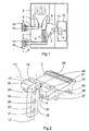
- FIG. 1 shows schematically a low-voltage circuit breaker on average arranged on the connection rails connectors according to the invention.
- FIG. 2 shows a preferred embodiment of the invention Connector with a connecting rail of a low-voltage circuit breaker.
- FIG 3 shows an arrangement of two according to the invention Connectors on a connection rail of a low-voltage circuit breaker.
- FIG. 4 shows a further arrangement of two according to the invention Connectors on a connection rail of a low-voltage circuit breaker.
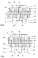
- FIG. 5 shows a sectional view along the section line A-B in Figure 3.
- Fig. 6 shows a sectional view along the section line C-D in FIG. 4.
- Fig. 1 is a low-voltage circuit breaker schematically 1 shown in section.
- the upper connection rail 3 Through the rear wall 2 of the Low-voltage circuit breakers 1 are the upper connection rail 3 and the lower connecting rail 4 passed through.
- On the upper connection rail 3 is the fixed switch contact 5 and on the lower connection rail 4 is via flexible conductor connections 6 on a contact carrier 7 located movable switch contact 8 connected.
- the switch drive 10 is the control shaft 11 with the Shift shaft lever 12, on which the tab 13 as a connecting element is attached to the contact carrier 7.
- the connectors of the invention 14 screwed, which is the connection between the horizontal Connection rails 3 and 4 of the low-voltage circuit breaker 1 and the vertical system side Form busbars 15 and 16.
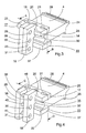
- FIG. 2 shows the connection of a preferred embodiment of the connector 14 according to the invention with a lower Connection rail 4 of a low-voltage circuit breaker 1.
- a lower Connection rail 4 of a low-voltage circuit breaker 1.
- extensions 24, 25, 26, 27 to support and fix the lower connecting rail 4 recognizable by the switch housing and comb-like Cutouts 28 for receiving the flexible conductor connections 6 to the movable switch contact.
- the connector 14 is for connecting the horizontally running lower connecting rail 4 with a not shown vertical system-side Track designed.
- the switch-side contact piece 17 of the connector 14 has three slots 19, 20, 21, the Function is described below. Off-center, between the middle slot 20 and an outer slot 21, is on the switch-side contact piece 17, pivoted in the plane by 90 °, the system-side contact piece 18 attached, and in such a way that the longitudinal axes L1, L2 of the two contact pieces 17, 18 at right angles to each other, but at a distance A run from each other, whereby the contact surface 22 of the switch-side contact piece 17 and the contact surface 23 do not spatially overlap the system-side contact piece 18, but are arranged side by side. Thereby is, as can be clearly seen in FIG. 1, a problem-free one Passing the vertical track on the system side 16 on the lower connecting rail 4 of the low-voltage circuit breaker 1 possible.
- the system-side contact piece 18, which has three holes 29, 30, 31 for fastening a system-side, vertically running, busbar is also off-center, between the middle bore 30 and the outer bore 29 attached to the switch-side contact piece 17. to secure attachment it has a widening 32, by means of which has a toothing of the two contact pieces 17, 18th at the place of attachment.
- the two contact pieces 17, 18 are positioned in the toothing after positioning Welding attached to each other. Due to the double eccentric Attachment of the contact pieces 17, 18 with each other the connector can be used universally, as described below becomes.
- FIG. 3 shows an arrangement of two connectors 14, 33 according to the invention on a lower connecting bar 4 of a low-voltage circuit breaker 1.
- the same elements of the connecting bar 4 are provided with the same reference numerals as in FIG. 2, but are not explained again.
- the connectors 14, 33 are designed for connecting the horizontally running lower connecting rail 4 to two vertically running, system-side power rails, not shown. The connection is therefore suitable for higher currents.
- the connector 14 is arranged on top of the connecting bar 4 and the connector 33 below it. With the help of the elongated holes 19, 20, 21 of the connector 14 arranged at the top of the connecting bar 4 and the elongated holes 34, 35, 36 (FIGS. 5 and 6) of the connector 33 arranged below the connecting bar 4, these are, when set, not shown Screw bolts, displaceable parallel to one another transversely to the axis of the connecting rail 4, as will be explained later in connection with FIGS. 5 and 6.
- FIG. 4 shows a further arrangement of two according to the invention Connectors 14, 33 on a lower connecting bar 4 a low-voltage circuit breaker 1.
- the connectors 14, 33 are for connection the horizontally running lower connecting rail 4 with three vertically running system-side, not shown Track designed.
- the connection can thus transmit even higher currents than the arrangement according to Fig. 3
- the connector 14 is on top of the connecting rail 4 arranged and the connector 33 below the same.
- the elongated holes 19, 20, 21 of the top of the connecting rail 4 arranged connector 14 and the elongated holes 34, 35, 36 (FIGS. 5 and 6) of the below the connecting rail 4th arranged connector 33 these are, when inserted, Screw bolts, not shown, transverse to the axis of the connecting rail 4 can be moved parallel to each other, as in Connection with FIGS. 5 and 6 will be explained later.
- FIG. 5 shows a sectional view along the section line A-B in Figure 3, with two added vertically after bottom running system rails 42, 43.
- holes 39, 40, 41 are provided above Connection rail 4 of the connector 14 with the elongated holes 19, 20, 21 arranged and below the connecting rail 4 of the connector 33 with the elongated holes 34, 35, 36.
- Die Connectors 14, 33 are by means of the through the elongated holes 19, 20, 21, 34, 35, 36 given mobility so that their system-side contact pieces 18, 38 touch. hereby On the plant side, this results from these contact pieces 18, 38 formed contact block, on which, as in connection described with Figure 3, two at a distance from each other arranged system-side busbars 42, 43 connected can be.
- Fig. 6 shows a sectional view along the section line C-D in Fig. 4, with three added vertically after bottom-running conductor rails 44, 45, 46.
- the advantages of the connector according to the invention consist in its universal applicability. It can't just be in busbars running at an angle to one another be connected, but also aligned around their longitudinal axis Busbars rotated by 90 °. You can, using the described Examples, every second contact piece two or more busbars on each contact surface can be connected one above the other, so that all desired Connection variants can be fulfilled.
Abstract
Description
Die Erfindung betrifft Verbinder für Stromschienen, die vorzugsweise zur Verbindung von Stromschienen von Schaltgeräten mit anlagenseitigen Stromschienen in Schaltanlagen geeignet sind.The invention relates to connectors for busbars, preferably for connecting power rails of switchgear Suitable for switchgear with power rails on the switchgear are.
So sind beispielsweise bei Niederspannungs-Leistungsschaltern die Stromschienen im allgemeinen als horizontale Anschlussschienen ausgeführt. Sie treten flach, in horizontaler Richtung aus der Rückwand des Schalters heraus. Sie sind für eine horizontale Weiterführung der anlagenseitigen Stromschienen, zum Beispiel bei Einschubschaltern, gut geeignet. In vielen Fällen, nämlich beim Festeinbau in eine Schaltzelle, sind aber Vertikalanschlüsse an die senkrecht verlaufenden anlagenseitigen Stromschienen erforderlich, da im allgemeinen von der oben angeordneten Sammelschiene einer Schaltanlage die Stromschienen senkrecht zum Schalter geführt sind und vom Schalter auch wieder senkrecht nach unten über die Wandler zum Kabel verlaufen.For example, in low-voltage circuit breakers the busbars generally as horizontal connection rails executed. They step flat, in the horizontal direction out of the back of the switch. You are for one horizontal continuation of the power rails on the system side, for example with slide-in switches, well suited. In many Cases, namely when permanently installed in a switchgear cell but vertical connections to the vertical system-side Conductor rails required, since generally from the busbar of a switchgear arranged above Busbars are guided perpendicular to the switch and from Switch again vertically downwards via the converter run to the cable.
Es sind also separate Zubehörteile zur Anordnung zwischen den senkrecht verlaufenden anlagenseitigen Stromschienen und den horizontal verlaufenden Anschlussschienen des Leistungsschalters erforderlich, die an die Anschlussschienen des Leistungsschalters und die anlagenseitigen Stromschienen angeschraubt werden.So there are separate accessories for arrangement between the vertically running power rails and the horizontally running connection rails of the circuit breaker required on the connection rails of the circuit breaker and screwed on the power rails on the system become.
Bei einem bekannten elektrischen Schalter ist ein gattungsgemäßer Verbinder für zumindest eine erste und eine zweite Stromschiene, die jeweils zumindest eine Anschlussfläche zum Kontaktieren mit jeweils einer Kontaktfläche des Verbinders aufweisen, vorgesehen, wobei die Anschlussfläche der zweiten Stromschiene senkrecht zur Anschlussfläche der ersten Stromschiene und parallel zur Achse der Stromrichtung in der ersten Stromschiene verläuft (EP 0 434 349 A1). - bei diesem bekannten Verbinder sind der ersten Stromschiene zugeordnete Kontaktflächen von einem geformten Metallband und der zweiten Stromschiene zugeordnete Kontaktflächen von vier Kontaktfingern gebildet, wobei das Metallband und die Kontaktfinger mittels eines Federelementes miteinander leitend verbunden sind.In a known electrical switch is a generic Connector for at least a first and a second Busbar, each with at least one connection surface Contact each with a contact surface of the connector have provided, the connection surface of the second Busbar perpendicular to the connection surface of the first busbar and parallel to the axis of the current direction in the first Track runs (EP 0 434 349 A1). - with this known connectors are assigned to the first busbar Contact surfaces from one shaped metal band and the second Contact surfaces of four contact fingers assigned to the busbar formed, the metal band and the contact fingers conductively connected to one another by means of a spring element are.
Es ist weiterhin bekannt, Verbinder für Stromschienen als massive Teile auszuführen, die jeweils nur für einen bestimmten Nennstrom geeignet sind. Daraus ergeben sich eine Vielzahl unterschiedlicher Teile und geringe Stückzahlen für die verschiedenen Stromstärken, verbunden mit hohen Teilekosten.It is also known as a connector for busbars perform massive parts, each for a specific one Rated current are suitable. This results in a multitude different parts and small quantities for the different currents, combined with high parts costs.
So zeigt die US-Patentschrift 3,287,534 einen großen Kompaktschalter, der stirnseitige Anschlüsse aufweist und speziell für den Einbau in Schaltanlagen geeignet ist. Bei diesem Schalter sind die Anschlüsse nicht aus dem Gehäuse herausgeführt, sondern es sind im Bereich der Gehäusewand Gewindebohrungen in den Anschlüssen vorgesehen. An diese sind mittels Schrauben jeweils Anschlussstücke mit je einer quadratischen Klemmfläche und im Quadrat angeordneten Befestigungslöchern angeschraubt. Von der genannten Klemmfläche ragt ein Verbindungssteg mit rechteckigem Querschnitt aus dem Schaltergehäuse heraus. Je nach der Stellung der quadratischen Klemmfläche zum Anschluss im Schaltgerät ist der Verbindungssteg horizontal oder Vertikal ausgerichtet und ermöglicht eine einfache Verbindung mit entsprechenden weiterführenden Stromschienen. For example, U.S. Patent 3,287,534 shows a large compact switch the front connections and special is suitable for installation in switchgear. With this Switches the connections are not led out of the housing, instead there are threaded holes in the area of the housing wall provided in the connections. To these are means Screw each connector with a square Clamping surface and fixing holes arranged in a square screwed. A connecting web protrudes from said clamping surface with a rectangular cross-section from the switch housing out. Depending on the position of the square clamping surface the connecting bridge is horizontal for connection in the switchgear or aligned vertically and allows easy Connection with corresponding further busbars.
Die US-Patentschrift 5,196,987 zeigt eine andere mögliche Form der Überleitung von einer horizontalen Schienenführung auf eine vertikale, wobei kombinierbare Bauteile als Anschluss- und Verbindungsteile Verwendung finden. Diese Teile bestehen aus mehreren Einzelteilen und haben einen komplizierten Aufbau.U.S. Patent 5,196,987 shows another possible one Form of the transition from a horizontal rail guide to a vertical, with combinable components as connection and connecting parts are used. These parts consist of several individual parts and have a complicated one Construction.
Bei diesen Lösungen sind abhängig von der Stromstärke viele unterschiedliche Teile erforderlich, was zu einer hohen Teilevielfalt und damit verbundenen hohen Teilekosten führt.With these solutions, there are many depending on the amperage different parts required, resulting in a large variety of parts and associated high parts costs.
Ausgehend von einem Verbinder mit den Merkmalen des Oberbegriffes des Patentanspruches 1 (EP 0 434 349 A1) liegt der Erfindung die Aufgabe zugrunde, den Verbinder derart universell zu gestalten, dass Verbindungen zur Übertragung unterschiedlicher Stromstärken für im rechten Winkel zueinander verlaufende oder für fluchtende, um 90° um ihre Längsachsen gedrehte Stromschienen geschaffen werden können.Starting from a connector with the features of the generic term of claim 1 (EP 0 434 349 A1) is the Invention, the object of the connector so universal to design that connection to transmit different Amperages for at right angles to each other running or for aligned, by 90 ° around their longitudinal axes turned busbars can be created.
Diese Aufgabe wird gemäß der vorliegenden Erfindung dadurch gelöst, dass die beiden Kontaktflächen an jeweils einem Kontaktstück des Verbinders ausgebildet sind und dass die Kontaktstücke an jeweils senkrecht zu ihrer Kontäktfläche verlaufenden, bezüglich des jeweiligen Kontaktstücks außermittig gelegenen Seiten derart miteinander leitend verbunden sind, dass die Längsachsen (L1, L2) der beiden Kontaktstücke (17, 18) im rechten Winkel zueinander, aber in einem Abstand (A) voneinander verlaufen, so dass die Kontaktflächen der Kontaktstücke (17, 18) einander nicht überschneiden oder überdecken, sondern nebeneinander um 90° gegeneinander geschwenkt angeordnet sind. This object is achieved according to the present invention in that the two contact surfaces are each formed on a contact piece of the connector and that the contact pieces are conductively connected to one another in each case on sides which are perpendicular to their contact surface and are located eccentrically with respect to the respective contact piece in such a way that the longitudinal axes (L 1 , L 2 ) of the two contact pieces (17, 18) at right angles to one another, but at a distance (A) from one another, so that the contact surfaces of the contact pieces (17, 18) do not overlap or overlap one another, but next to one another 90 ° are arranged pivoted against each other.
Vorteilhaft weist wenigstens ein Kontaktstück auf der dem anderen Kontaktstück zugewandten Seite einen Ansatz auf. Zweckmäßig können auch beide Kontaktstücke auf der dem anderen Kontaktstück zugewandten Seite einen Ansatz aufweisen. Diese Ansätze dienen dazu, dass bei der Herstellung des Verbinders in ihnen jeweils ein Schlitz mit einer Breite vorgesehen wird, die der Dicke des anderen Kontaktstücks entspricht. In diesen Schlitz wird dann beim Zusammenbau des Verbinders das Gegenkontaktstück eingeschoben und durch ein geeignetes Befestigungsverfahren, wie Schweißen oder Löten fixiert. Damit wird die vorstehende Forderung realisiert, dass die Kontaktflächen der Kontaktstücke des Verbinders im zusammengebauten Zustand keine Überschneidung aufweisen, damit die im rechten Winkel mit ihnen zu verbindenden Stromschienen an ihnen problemlos vorbeigeführt werden können.Advantageously, at least one contact piece points to the other Contact side facing an approach. expedient can also both contact pieces on the other Have a shoulder facing the contact piece. This Approaches are used to make the connector each provided a slot with a width which corresponds to the thickness of the other contact piece. In this slot is then when assembling the connector Counter contact piece inserted and by a suitable fastening method, such as welding or soldering. In order to the above requirement is realized that the contact surfaces the contact pieces of the connector in the assembled Condition have no overlap so the one on the right Brackets to be connected to them without any problems can be led past.
Darüber hinaus wird durch diese Befestigung eine höhere mechanische Festigkeit erzielt und weiterhin die Stromtragfähigkeit der Verbindung durch einen größeren leitenden Querschnitt erhöht. Beide wären beim Zusammenfügen nur an den Schmalseiten der Kontaktstücke möglicherweise nicht ausreichend.In addition, this attachment creates a higher mechanical Strength achieved and still the current carrying capacity the connection through a larger conductive cross section elevated. Both would only be attached to the Narrow sides of the contact pieces may not be sufficient.
Das erste Kontaktstück ist in vorteilhafter Ausgestaltung der Erfindung mit in Richtung seiner Längsachse angeordneten Langlöchern versehen, wodurch eine Verschiebbarkeit des Verbinders quer zur Achse der zu verbindenden Stromschiene ermöglicht wird.In an advantageous embodiment, the first contact piece is the Invention arranged in the direction of its longitudinal axis Provide elongated holes, which allows the connector to move transverse to the axis of the conductor rail to be connected becomes.
Dabei ist, insbesondere bei der Verwendung von zwei Verbindern, die Länge der Langlöcher gegebenenfalls abhängig von der Schienendicke der an den zweiten Kontaktstücken anzuschließenden Stromschienen, insbesondere dann, wenn drei Stromschienen angeschlossen werden sollen, von denen eine zwischen den zweiten Kontaktstücken der beiden Verbinder angeordnet ist, wie das im Bezug auf die Fig. 4 und 6 im nachfolgenden Ausführungsbeispiel ausführlich dargestellt ist.Here, especially when using two connectors, the length of the elongated holes may depend on the rail thickness of those to be connected to the second contact pieces Busbars, especially when three Busbars are to be connected, one of which arranged between the second contact pieces of the two connectors is like that with reference to FIGS. 4 and 6 below Embodiment is shown in detail.
Das zweite Kontaktstück ist in zweckmäßiger Ausführung mit in Richtung seiner Längsachse angeordneten Bohrungen versehen, mittels welcher die anzuschließenden anlagenseitigen Stromschienen angeschraubt werden können.The second contact piece is in an appropriate design with in Bores arranged in the direction of its longitudinal axis, by means of which the system-side busbars to be connected can be screwed on.
Vorteilhaft sind die Kontaktstücke in Richtung ihrer Längsachsen etwa so breit, wie die daran anzuschließenden beiderseits zu verbindenden Stromschienen. Da beispielsweise bei Niederspannungs-Leistungsschaltern Anschlussschienen angestrebt werden, die für alle Stromstärken gleiche Außenabmessungen aufweisen, ergibt sich in diesem Anwendungsbereich durch diese Anpassung keine erhöhte Teilevielfalt.The contact pieces in the direction of their longitudinal axes are advantageous about as wide as the ones to be connected on both sides busbars to be connected. For example, at Low-voltage circuit breakers connection rails sought be the same external dimensions for all currents have in this area of application no increased variety of parts due to this adjustment.
Durch die unsymmetrische Ausbildung des Verbinders und die Anordnung von Langlöchern in einem der beiden Kontaktstücke, kann, beispielsweise bei einer Verwendung des Verbinders zum Anschluss vertikaler anlagenseitiger Stromschienen an horizontal angeordnete Anschlussschienen von Niederspannungs-Leistungsschaltern, durch unterschiedliche Einbaulagen erreicht werden, dass wahlweise zwei derartige Verbinder, von unten und oben befestigt, so kombinierbar sind, dass die anlagenseitigen Kontaktstücke, an denen die anlagenseitigen Stromschienen angeschlossen sind, aneinander anliegen oder mit einem Abstand voneinander angeordnet sind. Dadurch ergibt sich eine Vielzahl von Anschlussmöglichkeiten für die anlagenseitigen Stromschienen, da an jeder Kontaktfläche auch zwei oder mehr Stromschienen übereinander angeschlossen werden können. Es sind somit dass alle gewünschten Anschlussvarianten erfüllbar.Due to the asymmetrical design of the connector and Arrangement of elongated holes in one of the two contact pieces, can, for example when using the connector for Connection of vertical system-side busbars to horizontal arranged connection rails of low-voltage circuit breakers, achieved through different installation positions be that optionally two such connectors, from attached below and above, can be combined so that the system side Contact pieces on which the system side Busbars are connected to each other or are arranged at a distance from each other. This gives a variety of connection options for the system side Conductor rails, as well on every contact surface two or more busbars can be connected one above the other can. It is therefore all the desired connection variants fulfilled.
Die Erfindung soll nachfolgend zum besseren Verständnis anhand von bevorzugten, den Schutzumfang nicht einschränkenden, Ausführungsbeispielen, unter Bezugnahme auf die zugehörige Zeichnung, näher erläutert werden. In den Beispielen wird der Gegenstand der Erfindung bei der Anwendung zur Verbindung horizontal verlaufender Anschlussschienen von Niederspannungs-Leistungsschaltern mit vertikal verlaufenden anlagenseitigen Stromschienen von Niederspannungs-Schaltanlagen beschrieben. The invention is intended to be better understood in the following of preferred, not restricting the scope of protection, Exemplary embodiments, with reference to the associated Drawing to be explained in more detail. In the examples, the Object of the invention when used to connect horizontally running connecting rails of low-voltage circuit breakers with vertical system-side Busbars of low-voltage switchgear described.
Die Fig.1 zeigt schematisch einen Niederspannungs-Leistungsschalter im Schnitt mit an den Anschlussschienen angeordneten erfindungsgemäßen Verbindern.1 shows schematically a low-voltage circuit breaker on average arranged on the connection rails connectors according to the invention.
Die Fig. 2 zeigt eine bevorzugte Ausführungsform des erfindungsgemäßen Verbinders mit einer Anschlussschiene eines Niederspannungs-Leistungsschalters.2 shows a preferred embodiment of the invention Connector with a connecting rail of a low-voltage circuit breaker.
Die Fig. 3 zeigt eine Anordnung von zwei erfindungsgemäßen Verbindern an einer Anschlussschiene eines Niederspannungs-Leistungsschalters.3 shows an arrangement of two according to the invention Connectors on a connection rail of a low-voltage circuit breaker.
Die Fig. 4 zeigt eine weitere Anordnung von zwei erfindungsgemäßen Verbindern an einer Anschlussschiene eines Niederspannungs-Leistungsschalters.4 shows a further arrangement of two according to the invention Connectors on a connection rail of a low-voltage circuit breaker.
Die Fig. 5 zeigt eine Schnittdarstellung gemäß der Schnittlinie A-B in der Fig. 3.5 shows a sectional view along the section line A-B in Figure 3.
Die Fig. 6 zeigt eine Schnittdarstellung gemäß der Schnittlinie C-D in der Fig. 4.Fig. 6 shows a sectional view along the section line C-D in FIG. 4.
In der Fig. 1 ist schematisch ein Niederspannungs-Leistungsschalter
1 im Schnitt dargestellt. Durch die Rückwand 2 des
Niederspannungs-Leistungsschalters 1 sind die obere Anschlussschiene
3 und die untere Anschlussschiene 4 hindurchgeführt.
An der oberen Anschlussschiene 3 befindet sich der
feste Schaltkontakt 5 und an der unteren Anschlussschiene 4
ist über flexible Leiterverbindungen 6 der auf einem Kontaktträger
7 befindliche bewegbare Schaltkontakt 8 angeschlossen.
Über dem festen Schaltkontakt 5 und dem bewegbaren Schaltkontakt
8 ist die Lichtbogenlöschkammer 9 angeordnet. Im Schalterantrieb
10 befindet sich die Schaltwelle 11 mit dem
Schaltwellenhebel 12, an welchem die Lasche 13 als Verbindungselement
zum Kontaktträger 7 befestigt ist. An den Anschlussschienen
3 und 4 sind die erfindungsgemäßen Verbinder
14 angeschraubt, welche die Verbindung zwischen den horizontalen
Anschlussschienen 3 und 4 des Niederspannungs-Leistungsschalters
1 und den vertikal verlaufenden anlagenseitigen
Stromschienen 15 und 16 bilden.In Fig. 1 is a low-voltage circuit breaker schematically
1 shown in section. Through the
Die Fig. 2 zeigt die Verbindung einer bevorzugten Ausführungsform
des erfindungsgemäßen Verbinders 14 mit einer unteren
Anschlussschiene 4 eines Niederspannungs-Leistungsschalters
1. An der unteren Anschlussschiene 4 sind Fortsätze 24,
25, 26, 27 zur Abstützung und Fixierung der unteren Anschlussschiene
4 am Schaltergehäuse zu erkennen und kammartige
Aussparungen 28 zur Aufnahme der flexiblen Leiterverbindungen
6 zum bewegbaren Schaltkontakt.2 shows the connection of a preferred embodiment
of the
In dieser Anordnung ist der Verbinder 14 zur Verbindung der
horizontal verlaufenden unteren Anschlussschiene 4 mit einer
nicht dargestellten vertikal verlaufenden anlagenseitigen
Stromschiene konzipiert. Das schalterseitige Kontaktstück 17
des Verbinders 14 weist drei Langlöcher 19, 20, 21 auf, deren
Funktion weiter unten beschrieben ist. Außermittig, zwischen
dem mittlerem Langloch 20 und einem äußeren Langloch 21, ist
am schalterseitigen Kontaktstück 17, in der Ebene um 90° geschwenkt,
das anlagenseitige Kontaktstück 18 befestigt, und
zwar so, dass die Längsachsen L1, L2 der beiden Kontaktstücke
17, 18 im rechten Winkel zueinander, aber in einem Abstand A
voneinander verlaufen, wodurch sich die Kontaktfläche 22 des
schalterseitigen Kontaktstückes 17 und die Kontaktfläche 23
des anlagenseitigen Kontaktstückes 18 räumlich nicht überschneiden,
sondern nebeneinander angeordnet sind. Dadurch
ist, wie in der Fig. 1 deutlich zu erkennen ist, ein problemloses
Vorbeiführen der vertikalen anlagenseitigen Stromschiene
16 an der unteren Anschlussschiene 4 des Niederspannungs-Leistungsschalters
1 möglich.In this arrangement, the
Das anlagenseitige Kontaktstück 18, welches drei Bohrungen
29, 30, 31 zur Befestigung einer anlagenseitigen, vertikal
verlaufenden, Stromschiene aufweist, ist ebenfalls außermittig,
zwischen der mittleren Bohrung 30 und der äußeren Bohrung
29 am schalterseitigen Kontaktstück 17 befestigt. Zur
sicheren Befestigung weist es eine Verbreiterung 32 auf, mittels
welcher eine Verzahnung der beiden Kontaktstücke 17, 18
am Ort der Befestigung erfolgt. Die beiden Kontaktstücke 17,
18 werden nach der Positionierung in der Verzahnung durch
Schweißen aneinander befestigt. Durch die zweifach außermittige
Befestigung der Kontaktstücke 17, 18 miteinander wird
der Verbinder universell verwendbar, wie nachfolgend beschrieben
wird.The system-
Die Fig.3 zeigt eine Anordnung von zwei erfindungsgemäßen
Verbindern 14, 33 an einer unteren Anschlussschiene 4 eines
Niederspannungs-Leistungsschalters 1. Gleiche Elemente der
Anschlussschiene 4 sind mit den gleichen Bezugszeichen wie in
der Fig.2 versehen, aber nicht nochmals erläutert. In dieser
Kombination sind die Verbinder 14, 33 zur Verbindung der horizontal
verlaufenden unteren Anschlussschiene 4 mit zwei
nicht dargestellten vertikal verlaufenden anlagenseitigen
Stromschiene konzipiert. Die Verbindung ist somit für höhere
Stromstärken geeignet. Dabei ist der Verbinder 14 oben auf
der Anschlussschiene 4 angeordnet und der Verbinder 33 unterhalb
derselben.
Mit Hilfe der Langlöcher 19, 20, 21 des oben auf der Anschlussschiene
4 angeordneten Verbinders 14 und der Langlöcher
34, 35, 36 (Fig. 5 und 6) des unterhalb der Anschlussschiene
4 angeordneten Verbinders 33 sind diese, bei ein gesetzten,
nicht dargestellten Schraubenbolzen, quer zur Achse
der Anschlussschiene 4 parallel zueinander verschiebbar, wie
das im Zusammenhang mit den Fig. 5 und 6 später erläutert
wird.3 shows an arrangement of two
With the help of the
Durch die außermittige Anordnung der Kontaktstücke 17, 18,
37, 38 der Verbinder 14, 33 zueinander und die dadurch vorhandenen
ungleich langen Schenkel, sind bei der dargestellten,
zusammengeschobenen Anordnung der Verbinder 14, 33 die
anlagenseitigen Kontaktstücke 18, 38 aneinander anliegend parallel
nebeneinander angeordnet, so dass auf jeder Seite außen
mittels der Bohrungen 29, 30, 31 und der Bohrungen 39,
40, 41 (Fig.4) je eine anlagenseitige Stromschiene durch Anschrauben
angeschlossen werden kann. Dabei wird der obere
Verbinder 14 so angeordnet, dass sich der lange Schenkel des
anlagenseitigen Kontaktstücks 18 nach unten erstreckt und der
untere Verbinder 33 derart, dass der lange Schenkel des anlagenseitigen
Kontaktstücks 38 nach oben gerichtet ist. Auf
diese Weise können zwei im Abstand voneinander angeordneten
anlagenseitigen Stromschienen problemlos angeschlossen werden.Due to the eccentric arrangement of the
Die Fig. 4 zeigt eine weitere Anordnung von zwei erfindungsgemäßen
Verbindern 14, 33 an einer unteren Anschlussschiene 4
eines Niederspannungs-Leistungsschalters 1.4 shows a further arrangement of two according to the
In dieser Kombination sind die Verbinder 14, 33 zur Verbindung
der horizontal verlaufenden unteren Anschlussschiene 4
mit drei nicht dargestellten vertikal verlaufenden anlagenseitigen
Stromschienen konzipiert. Die Verbindung kann somit
noch höhere Stromstärken übertragen, als die Anordnung nach
Fig. 3 In this combination, the
Auch hier ist der Verbinder 14 oben auf der Anschlussschiene
4 angeordnet und der Verbinder 33 unterhalb derselben. Mit
Hilfe der Langlöcher 19, 20, 21 des oben auf der Anschlussschiene
4 angeordneten Verbinders 14 und der Langlöcher 34,
35, 36 (Fig. 5 und 6) des unterhalb der Anschlussschiene 4
angeordneten Verbinders 33 sind diese, bei eingesetzten,
nicht dargestellten Schraubenbolzen, quer zur Achse der Anschlussschiene
4 parallel zueinander verschiebbar, wie das im
Zusammenhang mit den Fig. 5 und 6 später erläutert wird.
Durch die außermittige Anordnung der Kontaktstücke 17, 18,
37, 38 der Verbinder 14, 33 zueinander und die dadurch vorhandenen
ungleich langen Schenkel, sind bei der dargestellten,
auseinandergeschobenen Anordnung der Verbinder 14, 33
die anlagenseitigen Kontaktstücke 18, 38 parallel nebeneinander,
in einem Abstand voneinander angeordnet, welcher der
Dicke einer anlagenseitigen Stromschiene entspricht.Here, too, the
Dadurch können auf jeder Seite der anlagenseitigen Kontaktstücke
18, 38 mittels der Bohrungen 29, 30, 31, 39, 40,
41 außen je eine Stromschiene angeschlossen werden und zwischen
den beiden Kontaktstücken 18, 38 eine dritte Stromschiene.
Dabei ist auch hier der obere Verbinder 14 so angeordnet,
dass sich der lange Schenkel des anlagenseitigen Kontaktstücks
18 nach unten erstreckt und der untere Verbinder
33 derart, dass der lange Schenkel des anlagenseitigen Kontaktstücks
38 nach oben gerichtet ist. Auf diese Weise können
problemlos drei im Abstand voneinander angeordneten anlagenseitige
Stromschienen angeschlossen werden.This allows contact pieces on each side of the
Die Fig.5 zeigt eine Schnittdarstellung gemäß der Schnittlinie A-B in der Fig.3, mit zwei hinzugefügten vertikal nach unten verlaufenden anlagenseitigen Stromschienen 42, 43. 5 shows a sectional view along the section line A-B in Figure 3, with two added vertically after bottom running system rails 42, 43.
Gemäß der Fig.3 ist oberhalb der mit Bohrungen 39, 40,41 versehenen
Anschlussschiene 4 der Verbinder 14 mit den Langlöchern
19, 20, 21 angeordnet und unterhalb der Anschlussschiene
4 der Verbinder 33 mit den Langlöchern 34, 35, 36. Die
Verbinder 14, 33 sind mittels der durch die Langlöcher 19,
20, 21, 34, 35, 36 gegebenen Bewegbarkeit so verschoben, dass
sich ihre anlagenseitigen Kotaktstücke 18, 38 berühren. Hierdurch
ergibt sich anlagenseitig ein aus diesen Kontaktstücken
18, 38 gebildeter Kontaktblock, an welchen, wie im Zusammenhang
mit der Fig.3 beschrieben, zwei im Abstand voneinander
angeordnete anlagenseitige Stromschienen 42, 43 angeschlossen
werden können.According to FIG. 3, holes 39, 40, 41 are provided above
Die Fig. 6 zeigt eine Schnittdarstellung gemäß der Schnittlinie
C-D in der Fig. 4, mit drei hinzugefügten vertikal nach
unten verlaufenden anlagenseitigen Stromschienen 44, 45, 46.Fig. 6 shows a sectional view along the section line
C-D in Fig. 4, with three added vertically after
bottom-running
Gemäß der Fig. 4 ist oberhalb der mit Bohrungen 39, 40,41
versehenen Anschlussschiene 4 der Verbinder 14 mit den Langlöchern
19, 20, 21 angeordnet und unterhalb der Anschlussschiene
4 der Verbinder 33 mit den Langlöchern 34, 35, 36.
Die Verbinder 14, 33 sind mittels der durch die Langlöcher
19, 20, 21, 34, 35, 36 gegebenen Bewegbarkeit so verschoben,
dass ihre anlagenseitigen Kontaktstücke 18, 38 parallel nebeneinander,
in einem Abstand voneinander angeordnet sind,
welcher der Dicke einer anlagenseitigen Stromschiene entspricht.
Dadurch können auf jeder Seite der anlagenseitigen
Kontaktstücke 18, 38 außen je eine anlagenseitige Stromschiene
44, 46 angeschlossen werden und zwischen den beiden Kontaktstücken
18, 38 eine dritte anlagenseitige Stromschiene
45, wie das unter Bezugnahme auf die Fig. 4 bereits beschrieben
wurde. 4 is above that with
Die Vorteile des erfindungsgemäßen Verbinders bestehen in seiner universellen Verwendbarkeit. Es können nicht nur in einem Winkel zueinander verlaufende Stromschienen miteinander verbunden werden, sondern auch fluchtende um ihre Längsachse um 90° gedrehte Stromschienen. Dabei können, über die beschriebenen Beispiele hinaus, an jedem zweiten Kontaktstück an jeder Kontaktfläche auch zwei oder mehr Stromschienen übereinander angeschlossen werden, so dass alle gewünschten Anschlussvarianten erfüllbar sind.The advantages of the connector according to the invention consist in its universal applicability. It can't just be in busbars running at an angle to one another be connected, but also aligned around their longitudinal axis Busbars rotated by 90 °. You can, using the described Examples, every second contact piece two or more busbars on each contact surface can be connected one above the other, so that all desired Connection variants can be fulfilled.
Claims (8)
- Connector for at least one first and one second busbar which each have at least one connecting surface for making contact with in each case one contact surface of the connector, with the connecting surface of the second busbar running at right angles to the connecting surface of the first busbar, and parallel to the axis of the current direction in the first busbar,
characterized in that the two contact surfaces (22, 23) are formed on in each case one contact piece (17, 18) of the connector, and in that the contact pieces (17, 18) are conductively connected to one another on faces which in each case run at right angles to their contact surface and are located eccentrically with respect to the respective contact piece, such that the longitudinal axes (L1, L2) of the two contact pieces (17, 18) run at right angles to one another, but at a distance (A) from one another, so that the contact surfaces of the contact pieces (17, 18) do not intersect or cover one another, but are arranged swivelled through 90° with respect to one another, alongside one another. - Connector according to Claim 1,
characterized in that at least one contact piece (17, 18) has an attachment on the side facing the other contact piece (18, 17). - Connector according to Claim 1,
characterized in that both contact pieces (17, 18) have an attachment on the side facing the respective other contact piece (18, 17). - Connector according to one of Claims 1 to 3,
characterized in that the first of the two contact pieces (17; 37) is provided with elongated holes (19, 20, 21; 34, 35 36) for its attachment to the first busbar (4) which elongated holes (19, 20, 21; 34, 35 36) are aligned along a longitudinal axis (L1) which is shared by them, with the longitudinal axis (L1) running at right angles to the contact surface (23) of the second contact piece (18; 38). - Connector according to one of Claims 1 to 4,
characterized in that the second contact piece (18; 38) is provided with holes (29, 30, 31; 39, 40, 41) which are aligned along a common longitudinal axis (L2), for its attachment to the second busbar (43; 42),
with the longitudinal axis (L2) running at right angles to the contact surface (22) of the first contact piece (17; 37). - Connector according to one of Claims 1 to 5,
characterized in that the contact surface of the contact piece (17; 18) and the connecting surface of the busbar (4; 43) on which it rests each have approximately the same width at right angles to the axis of the current direction in this busbar. - Connector according to one of Claims 1 to 6,
characterized in that the first contact piece (17), which rests on the first busbar (4), is offset with respect to a central arrangement on the second contact piece (18), which rests on the second busbar (43), such that, on connection of the connector to a second connecting side of the first busbar (4) in a position rotating through 180° about the axis of the current direction in this busbar, the second contact surface (23) is arranged essentially aligned with respect to its position before the rotation with respect to its surface normal. - Connector according to one of Claims 1 to 7,
characterized in that the second contact piece (18), which rests on the second busbar (43), is offset with respect to a central arrangement on the first contact piece (17), which rests on the first busbar (4), such that when a second connector (33) is arranged such that it is swivelled through 180° with respect to the first connector (14) about the axis of the current direction in the first busbar, and in the case of second contact surfaces which not only rest on one another but are also separated by a value which corresponds to the thickness of the second busbar (45) at right angles to its connecting surface
the first contact surfaces (22) do not overhang the first connecting surfaces in the direction at right angles to the axis of the current direction in the first busbar.
Applications Claiming Priority (3)
| Application Number | Priority Date | Filing Date | Title |
|---|---|---|---|
| DE10022639A DE10022639C1 (en) | 2000-04-28 | 2000-04-28 | Right angle connector joining main bus bar to e.g. switchgear, comprises two joined sections having offset, non-intersecting contact surfaces |
| DE10022639 | 2000-04-28 | ||
| PCT/DE2001/000946 WO2001084684A1 (en) | 2000-04-28 | 2001-03-07 | Connector for conductor bars |
Publications (2)
| Publication Number | Publication Date |
|---|---|
| EP1277258A1 EP1277258A1 (en) | 2003-01-22 |
| EP1277258B1 true EP1277258B1 (en) | 2004-09-15 |
Family
ID=7641368
Family Applications (1)
| Application Number | Title | Priority Date | Filing Date |
|---|---|---|---|
| EP01919192A Expired - Lifetime EP1277258B1 (en) | 2000-04-28 | 2001-03-07 | Connector for conductor bars |
Country Status (7)
| Country | Link |
|---|---|
| US (1) | US6921862B2 (en) |
| EP (1) | EP1277258B1 (en) |
| JP (1) | JP2003532992A (en) |
| CN (1) | CN1237678C (en) |
| DE (2) | DE10022639C1 (en) |
| HK (1) | HK1056440A1 (en) |
| WO (1) | WO2001084684A1 (en) |
Families Citing this family (17)
| Publication number | Priority date | Publication date | Assignee | Title |
|---|---|---|---|---|
| ITBS20040007A1 (en) * | 2004-01-20 | 2004-04-20 | Bbi Electric Spa | UNIT FOR THE DERIVATION OF CURRENT FROM ELECTRIC DUCTS TO BARS |
| FR2911223B1 (en) * | 2007-01-10 | 2015-03-20 | Auxel | ATTACHMENT FOR FIXING A DISTRIBUTOR. |
| DE102009010457A1 (en) * | 2009-02-13 | 2010-08-19 | August Schmid | Closed busbar system for low voltage distribution |
| US7806711B2 (en) * | 2009-02-27 | 2010-10-05 | American Power Conversion Corporation | Electrical connector |
| US20110140686A1 (en) * | 2009-12-16 | 2011-06-16 | Lineage Power Corporation | Thermal extension structures for monitoring bus bar terminations |
| CN101964456B (en) * | 2010-08-17 | 2016-01-20 | 上海一开电气集团有限公司 | Bus connection structure |
| DE102011053724A1 (en) * | 2011-09-16 | 2013-03-21 | Demag Cranes & Components Gmbh | Conductor rail with busbars detachably connectable via a connector |
| DE102011053725A1 (en) * | 2011-09-16 | 2013-03-21 | Demag Cranes & Components Gmbh | Conductor rail with a connector releasably connectable busbars and mounting method for this purpose |
| DE102011053726A1 (en) * | 2011-09-16 | 2013-03-21 | Demag Cranes & Components Gmbh | Conductor rail with busbars detachably connectable via a connector |
| US9491895B2 (en) * | 2013-03-03 | 2016-11-08 | General Electric Company | Power distribution rack bus bar assembly and method of assembling the same |
| EP3127201B1 (en) | 2014-03-31 | 2020-11-18 | Schneider Electric USA, Inc. | Integrated connector for backplane of a draw out breaker chassis |
| CN106905414B (en) * | 2017-03-15 | 2020-08-07 | 中国医学科学院医药生物技术研究所 | Novel actinomycin A and preparation method and application thereof |
| CN106971867B (en) * | 2017-05-24 | 2019-12-31 | 首瑞(天津)电气设备有限公司 | Moving contact and circuit breaker |
| DE102017213150A1 (en) * | 2017-07-31 | 2019-01-31 | Robert Bosch Gmbh | Electrical plug contact for high current applications and connector system for high current applications |
| WO2020046850A1 (en) * | 2018-08-27 | 2020-03-05 | Molex, Llc | Hinged busbar assembly |
| US11355902B2 (en) * | 2019-01-28 | 2022-06-07 | TE Connectivity Services Gmbh | Power connector for a bus bar |
| CN110993453B (en) * | 2019-11-29 | 2021-11-05 | 河南平高通用电气有限公司 | Conductive connection device and direct current breaker using same |
Family Cites Families (19)
| Publication number | Priority date | Publication date | Assignee | Title |
|---|---|---|---|---|
| US3287534A (en) * | 1963-08-30 | 1966-11-22 | Westinghouse Electric Corp | Circuit interrupter structure with improved terminal means |
| US4752233A (en) * | 1987-07-20 | 1988-06-21 | General Electric Company | Electric power panelboard adapter module |
| DE3808197A1 (en) * | 1988-03-11 | 1989-10-05 | Hans Simon | ELECTRICAL TERMINAL |
| US5053918A (en) | 1989-12-22 | 1991-10-01 | Connectron, Inc. | Three phase bus bar apparatus having selectively positioned interexchangeable links |
| JP2897509B2 (en) * | 1992-01-24 | 1999-05-31 | 三菱電機株式会社 | Busbar connection device |
| US5196987A (en) * | 1992-03-27 | 1993-03-23 | General Electric Company | Electric busway power take-off assembly |
| US5351165A (en) * | 1992-12-31 | 1994-09-27 | Siemens Energy & Automation, Inc. | Main circuit breaker or other circuit protective device connector installation kit for panelboards |
| AUPP008497A0 (en) | 1997-10-29 | 1997-11-20 | Tappat Engineering Pty Limited | Electricity distribution system |
| IT1303292B1 (en) * | 1998-10-30 | 2000-11-06 | Abb Ricerca Spa | CONDUCTIVE BAR FOR THE DISTRIBUTION OF ELECTRICITY. |
| DE10001184B4 (en) * | 2000-01-14 | 2007-06-06 | Rittal Gmbh & Co. Kg | Device for connecting busbars of a busbar system with the terminals of an electrical installation device |
| DE10001462C1 (en) * | 2000-01-15 | 2001-08-16 | Loh Kg Rittal Werk | Kit for connecting bus bars to electrical fitting contacts has angled connectors, flat bar sections and Z-angled sections made of flat material of identical cross-section |
| US6201722B1 (en) * | 2000-06-02 | 2001-03-13 | Astec International Limited | Inter-bay bipolar DC bus link |
| US6420655B1 (en) * | 2000-11-13 | 2002-07-16 | Delta Electronics, Inc. | Structure of bus bar assembly for power supply |
| US6603075B1 (en) * | 2000-12-20 | 2003-08-05 | General Electric Company | Vertical bus power connector |
| US6445570B1 (en) * | 2001-01-30 | 2002-09-03 | Eaton Corporation | Automatically operating interlock assembly requiring an electrical cabinet to be closed before connection of the equipment |
| US6521837B2 (en) * | 2001-02-23 | 2003-02-18 | Universal Electric Corporation | Electrical busway housing system and connection means therefor |
| US6762362B1 (en) * | 2001-05-24 | 2004-07-13 | Emc Corporation | Apparatus and method for connecting a power supply to multiple backplanes within an electronic equipment cabinet |
| US6786749B2 (en) * | 2002-11-06 | 2004-09-07 | Eaton Corporation | Universal connector for securing bus bars to electrical equipment |
| US6674006B1 (en) * | 2003-01-10 | 2004-01-06 | D-M-E Company | Load configurable electrical distribution bus |
-
2000
- 2000-04-28 DE DE10022639A patent/DE10022639C1/en not_active Expired - Fee Related
-
2001
- 2001-03-07 DE DE50103632T patent/DE50103632D1/en not_active Expired - Lifetime
- 2001-03-07 CN CNB018121438A patent/CN1237678C/en not_active Expired - Fee Related
- 2001-03-07 US US10/258,656 patent/US6921862B2/en not_active Expired - Lifetime
- 2001-03-07 EP EP01919192A patent/EP1277258B1/en not_active Expired - Lifetime
- 2001-03-07 WO PCT/DE2001/000946 patent/WO2001084684A1/en active IP Right Grant
- 2001-03-07 JP JP2001581393A patent/JP2003532992A/en not_active Withdrawn
-
2003
- 2003-11-27 HK HK03108667A patent/HK1056440A1/en not_active IP Right Cessation
Also Published As
| Publication number | Publication date |
|---|---|
| DE10022639C1 (en) | 2001-10-04 |
| US6921862B2 (en) | 2005-07-26 |
| US20030166353A1 (en) | 2003-09-04 |
| DE50103632D1 (en) | 2004-10-21 |
| WO2001084684A1 (en) | 2001-11-08 |
| JP2003532992A (en) | 2003-11-05 |
| EP1277258A1 (en) | 2003-01-22 |
| HK1056440A1 (en) | 2004-02-13 |
| CN1237678C (en) | 2006-01-18 |
| CN1440580A (en) | 2003-09-03 |
Similar Documents
| Publication | Publication Date | Title |
|---|---|---|
| EP1277258B1 (en) | Connector for conductor bars | |
| DE3621268C2 (en) | Three-phase encapsulated, gas-insulated switchgear | |
| DE102007053535B4 (en) | Connection module and unit consisting of a switching device, a connection module and an adapter | |
| WO2010052080A2 (en) | Housing segment for a connecting point of bus bar arrangements | |
| DE19506056C2 (en) | Adapter plate for attachment to a multi-phase track system | |
| EP0168596B1 (en) | Connecting clamp and method of making a connecting clamp | |
| EP1271727B1 (en) | Electrical installation apparatus | |
| DE4305746C2 (en) | Load switch arrangement and housing for receiving this load switch arrangement | |
| EP2124306B1 (en) | Electrical switching unit for an electrical switching assembly, in particular for medium voltage | |
| EP0916148A1 (en) | Switching chamber housing for a power switch and housing modules for producing such a switching chamber housing | |
| WO2012068601A1 (en) | Connection assembly | |
| EP1297547B1 (en) | Connecting bars for electrical devices and apparatus for different nominal currents having a cavity | |
| DE102004033680A1 (en) | load resistance | |
| EP1472766A1 (en) | Connecting or distributing device for electrical installation equipment | |
| DE4326401A1 (en) | Arrangement consisting of a circuit breaker part and a fuse part | |
| EP1356548A1 (en) | Contact device for the detachable connection of a mobile appliance unit to fixed conductor rails | |
| DE10014214B4 (en) | A bus bar connector | |
| DE4130815A1 (en) | Flexible bus=bar for electrical energy distribution - has two pivots joining three sections of flat parallel bus=bars, the unit forming 'Z' or 'V' shape | |
| DE10260371A1 (en) | Low-voltage circuit breakers | |
| EP2273634B1 (en) | Electric switch assembly, in particular medium voltage medium voltage switching assembly | |
| DE2847376C2 (en) | Single or multi-pole disconnector arrangement for encapsulated switchgear | |
| DE102006038739A1 (en) | Platform for plugging in an electricity meter | |
| EP0432859B1 (en) | Contact device for detachably receiving multipole switchgear break contacts | |
| WO2012130527A1 (en) | Electrical pin configuration of a withdrawable medium-voltage switchgear | |
| EP0895663B1 (en) | Tap-off unit, especially for busbar trunking systems |
Legal Events
| Date | Code | Title | Description |
|---|---|---|---|
| PUAI | Public reference made under article 153(3) epc to a published international application that has entered the european phase |
Free format text: ORIGINAL CODE: 0009012 |
|
| 17P | Request for examination filed |
Effective date: 20021016 |
|
| AK | Designated contracting states |
Kind code of ref document: A1 Designated state(s): AT BE CH CY DE DK ES FI FR GB GR IE IT LI LU MC NL PT SE TR |
|
| 17Q | First examination report despatched |
Effective date: 20031029 |
|
| GRAP | Despatch of communication of intention to grant a patent |
Free format text: ORIGINAL CODE: EPIDOSNIGR1 |
|
| GRAS | Grant fee paid |
Free format text: ORIGINAL CODE: EPIDOSNIGR3 |
|
| GRAA | (expected) grant |
Free format text: ORIGINAL CODE: 0009210 |
|
| AK | Designated contracting states |
Kind code of ref document: B1 Designated state(s): DE FR GB IT |
|
| REG | Reference to a national code |
Ref country code: GB Ref legal event code: FG4D Free format text: NOT ENGLISH |
|
| REG | Reference to a national code |
Ref country code: IE Ref legal event code: FG4D Free format text: GERMAN |
|
| REF | Corresponds to: |
Ref document number: 50103632 Country of ref document: DE Date of ref document: 20041021 Kind code of ref document: P |
|
| GBT | Gb: translation of ep patent filed (gb section 77(6)(a)/1977) |
Effective date: 20050115 |
|
| REG | Reference to a national code |
Ref country code: IE Ref legal event code: FD4D |
|
| PLBE | No opposition filed within time limit |
Free format text: ORIGINAL CODE: 0009261 |
|
| STAA | Information on the status of an ep patent application or granted ep patent |
Free format text: STATUS: NO OPPOSITION FILED WITHIN TIME LIMIT |
|
| ET | Fr: translation filed | ||
| 26N | No opposition filed |
Effective date: 20050616 |
|
| PGFP | Annual fee paid to national office [announced via postgrant information from national office to epo] |
Ref country code: GB Payment date: 20080313 Year of fee payment: 8 Ref country code: IT Payment date: 20080326 Year of fee payment: 8 |
|
| GBPC | Gb: european patent ceased through non-payment of renewal fee |
Effective date: 20090307 |
|
| PG25 | Lapsed in a contracting state [announced via postgrant information from national office to epo] |
Ref country code: GB Free format text: LAPSE BECAUSE OF NON-PAYMENT OF DUE FEES Effective date: 20090307 |
|
| PGFP | Annual fee paid to national office [announced via postgrant information from national office to epo] |
Ref country code: FR Payment date: 20100325 Year of fee payment: 10 |
|
| PGFP | Annual fee paid to national office [announced via postgrant information from national office to epo] |
Ref country code: DE Payment date: 20100521 Year of fee payment: 10 |
|
| PG25 | Lapsed in a contracting state [announced via postgrant information from national office to epo] |
Ref country code: IT Free format text: LAPSE BECAUSE OF NON-PAYMENT OF DUE FEES Effective date: 20090307 |
|
| REG | Reference to a national code |
Ref country code: FR Ref legal event code: ST Effective date: 20111130 |
|
| PG25 | Lapsed in a contracting state [announced via postgrant information from national office to epo] |
Ref country code: FR Free format text: LAPSE BECAUSE OF NON-PAYMENT OF DUE FEES Effective date: 20110331 Ref country code: DE Free format text: LAPSE BECAUSE OF NON-PAYMENT OF DUE FEES Effective date: 20111001 |
|
| REG | Reference to a national code |
Ref country code: DE Ref legal event code: R119 Ref document number: 50103632 Country of ref document: DE Effective date: 20111001 |