EP1276448B1 - Apparatus and methods for packaging and storing moisture-sensitive products in resealable pouches - Google Patents
Apparatus and methods for packaging and storing moisture-sensitive products in resealable pouches Download PDFInfo
- Publication number
- EP1276448B1 EP1276448B1 EP00970513A EP00970513A EP1276448B1 EP 1276448 B1 EP1276448 B1 EP 1276448B1 EP 00970513 A EP00970513 A EP 00970513A EP 00970513 A EP00970513 A EP 00970513A EP 1276448 B1 EP1276448 B1 EP 1276448B1
- Authority
- EP
- European Patent Office
- Prior art keywords
- pouch
- product
- length
- moisture
- opening
- Prior art date
- Legal status (The legal status is an assumption and is not a legal conclusion. Google has not performed a legal analysis and makes no representation as to the accuracy of the status listed.)
- Expired - Lifetime
Links
- 238000000034 method Methods 0.000 title claims abstract description 26
- 238000004806 packaging method and process Methods 0.000 title claims description 19
- 238000007789 sealing Methods 0.000 claims abstract description 73
- 238000005266 casting Methods 0.000 claims abstract description 10
- 230000000399 orthopedic effect Effects 0.000 claims abstract description 8
- 230000006835 compression Effects 0.000 claims description 51
- 238000007906 compression Methods 0.000 claims description 51
- 239000000463 material Substances 0.000 claims description 24
- 239000000725 suspension Substances 0.000 claims description 3
- 239000011111 cardboard Substances 0.000 description 7
- 238000003860 storage Methods 0.000 description 6
- 239000005022 packaging material Substances 0.000 description 5
- 230000008901 benefit Effects 0.000 description 4
- 238000010276 construction Methods 0.000 description 4
- -1 polypropylene Polymers 0.000 description 4
- 230000002028 premature Effects 0.000 description 4
- 229910052782 aluminium Inorganic materials 0.000 description 3
- XAGFODPZIPBFFR-UHFFFAOYSA-N aluminium Chemical compound [Al] XAGFODPZIPBFFR-UHFFFAOYSA-N 0.000 description 3
- 239000006260 foam Substances 0.000 description 3
- 239000011888 foil Substances 0.000 description 3
- 239000004620 low density foam Substances 0.000 description 3
- 239000004033 plastic Substances 0.000 description 3
- 229920003023 plastic Polymers 0.000 description 3
- 239000004698 Polyethylene Substances 0.000 description 2
- 230000009471 action Effects 0.000 description 2
- 230000008878 coupling Effects 0.000 description 2
- 238000010168 coupling process Methods 0.000 description 2
- 238000005859 coupling reaction Methods 0.000 description 2
- 229920000573 polyethylene Polymers 0.000 description 2
- 230000036316 preload Effects 0.000 description 2
- 235000014676 Phragmites communis Nutrition 0.000 description 1
- 239000004743 Polypropylene Substances 0.000 description 1
- 230000001154 acute effect Effects 0.000 description 1
- 239000002390 adhesive tape Substances 0.000 description 1
- 230000000712 assembly Effects 0.000 description 1
- 238000000429 assembly Methods 0.000 description 1
- 238000001266 bandaging Methods 0.000 description 1
- 230000004888 barrier function Effects 0.000 description 1
- 238000005452 bending Methods 0.000 description 1
- 230000000694 effects Effects 0.000 description 1
- 230000002349 favourable effect Effects 0.000 description 1
- 238000009499 grossing Methods 0.000 description 1
- 229920000554 ionomer Polymers 0.000 description 1
- 238000004519 manufacturing process Methods 0.000 description 1
- 230000013011 mating Effects 0.000 description 1
- 229910052751 metal Inorganic materials 0.000 description 1
- 239000002184 metal Substances 0.000 description 1
- 230000004048 modification Effects 0.000 description 1
- 238000012986 modification Methods 0.000 description 1
- 230000035515 penetration Effects 0.000 description 1
- 230000002093 peripheral effect Effects 0.000 description 1
- 229920001155 polypropylene Polymers 0.000 description 1
- 230000008569 process Effects 0.000 description 1
- 230000009467 reduction Effects 0.000 description 1
- 239000011347 resin Substances 0.000 description 1
- 229920005989 resin Polymers 0.000 description 1
- 238000000926 separation method Methods 0.000 description 1
- 238000004513 sizing Methods 0.000 description 1
- 239000002699 waste material Substances 0.000 description 1
- 230000037303 wrinkles Effects 0.000 description 1
Images


Classifications
-
- B—PERFORMING OPERATIONS; TRANSPORTING
- B65—CONVEYING; PACKING; STORING; HANDLING THIN OR FILAMENTARY MATERIAL
- B65D—CONTAINERS FOR STORAGE OR TRANSPORT OF ARTICLES OR MATERIALS, e.g. BAGS, BARRELS, BOTTLES, BOXES, CANS, CARTONS, CRATES, DRUMS, JARS, TANKS, HOPPERS, FORWARDING CONTAINERS; ACCESSORIES, CLOSURES, OR FITTINGS THEREFOR; PACKAGING ELEMENTS; PACKAGES
- B65D83/00—Containers or packages with special means for dispensing contents
- B65D83/08—Containers or packages with special means for dispensing contents for dispensing thin flat articles in succession
- B65D83/0847—Containers or packages with special means for dispensing contents for dispensing thin flat articles in succession through an aperture at the junction of two walls
-
- A—HUMAN NECESSITIES
- A61—MEDICAL OR VETERINARY SCIENCE; HYGIENE
- A61F—FILTERS IMPLANTABLE INTO BLOOD VESSELS; PROSTHESES; DEVICES PROVIDING PATENCY TO, OR PREVENTING COLLAPSING OF, TUBULAR STRUCTURES OF THE BODY, e.g. STENTS; ORTHOPAEDIC, NURSING OR CONTRACEPTIVE DEVICES; FOMENTATION; TREATMENT OR PROTECTION OF EYES OR EARS; BANDAGES, DRESSINGS OR ABSORBENT PADS; FIRST-AID KITS
- A61F15/00—Auxiliary appliances for wound dressings; Dispensing containers for dressings or bandages
- A61F15/001—Packages or dispensers for bandages, cotton balls, drapes, dressings, gauze, gowns, sheets, sponges, swabsticks or towels
- A61F15/002—Packages or dispensers for bandages, cotton balls, drapes, dressings, gauze, gowns, sheets, sponges, swabsticks or towels dispensers for web or tape like bandages
-
- B—PERFORMING OPERATIONS; TRANSPORTING
- B65—CONVEYING; PACKING; STORING; HANDLING THIN OR FILAMENTARY MATERIAL
- B65D—CONTAINERS FOR STORAGE OR TRANSPORT OF ARTICLES OR MATERIALS, e.g. BAGS, BARRELS, BOTTLES, BOXES, CANS, CARTONS, CRATES, DRUMS, JARS, TANKS, HOPPERS, FORWARDING CONTAINERS; ACCESSORIES, CLOSURES, OR FITTINGS THEREFOR; PACKAGING ELEMENTS; PACKAGES
- B65D33/00—Details of, or accessories for, sacks or bags
- B65D33/16—End- or aperture-closing arrangements or devices
- B65D33/1658—Elements for flattening or folding the mouth portion
- B65D33/1675—Hinged clips
-
- B—PERFORMING OPERATIONS; TRANSPORTING
- B65—CONVEYING; PACKING; STORING; HANDLING THIN OR FILAMENTARY MATERIAL
- B65D—CONTAINERS FOR STORAGE OR TRANSPORT OF ARTICLES OR MATERIALS, e.g. BAGS, BARRELS, BOTTLES, BOXES, CANS, CARTONS, CRATES, DRUMS, JARS, TANKS, HOPPERS, FORWARDING CONTAINERS; ACCESSORIES, CLOSURES, OR FITTINGS THEREFOR; PACKAGING ELEMENTS; PACKAGES
- B65D83/00—Containers or packages with special means for dispensing contents
- B65D83/08—Containers or packages with special means for dispensing contents for dispensing thin flat articles in succession
- B65D83/0894—Containers or packages with special means for dispensing contents for dispensing thin flat articles in succession the articles being positioned relative to one another or to the container in a special way, e.g. for facilitating dispensing, without additional support
-
- A—HUMAN NECESSITIES
- A61—MEDICAL OR VETERINARY SCIENCE; HYGIENE
- A61F—FILTERS IMPLANTABLE INTO BLOOD VESSELS; PROSTHESES; DEVICES PROVIDING PATENCY TO, OR PREVENTING COLLAPSING OF, TUBULAR STRUCTURES OF THE BODY, e.g. STENTS; ORTHOPAEDIC, NURSING OR CONTRACEPTIVE DEVICES; FOMENTATION; TREATMENT OR PROTECTION OF EYES OR EARS; BANDAGES, DRESSINGS OR ABSORBENT PADS; FIRST-AID KITS
- A61F13/00—Bandages or dressings; Absorbent pads
- A61F13/04—Plaster of Paris bandages; Other stiffening bandages
Definitions
- This invention relates to moisture-sensitive products and, more particularly, to apparatus and methods for packaging and storing continuous length, moisture-curable orthopedic splinting/casting product in moisture-proof pouches and containers.
- any package for use with these products preferably forms a hermetic seal which is moisture-impermeable.
- U.S. Pat. Nos. 4,770,299 to Parker, 4,869,046 to Parker, and 4,899,738 to Parker all disclose a medical bandaging product packaged in an outer sleeve of a moisture-impermeable material such as an aluminum foil laminate.
- the moisture-proof outer sleeve package disclosed is essentially as long as the product contained therein.
- the packaged product is typically rolled up and placed in a box where it may be unrolled such that a portion of the package (with the product therein) may be cut to length.
- the remaining packaging material is then resealed after each use.
- This packaging system has the advantage of allowing the product to be cut to the particular length desired, but also has several disadvantages.
- packaging the material as a roll in a box produces many creases in the relatively stiff aluminum foil laminate typically used to form the sleeve.
- the creases potentially are a source of pinholes which leak and cause premature curing of the product in the package.
- a relatively large amount of packaging material is used which adds to the cost of the product.
- the package appears to include two side panels having an enlarged area and tapering to form the sides of the extended sleeve and a strip used to connect the sides of the package and form the top and bottom of the extended sleeve.
- this package is not easily manufactured using existing packaging equipment.
- the patent also fails to disclose an effective and easy-to-use means of sealing the extended sleeve during and between uses.
- the container includes a magnetic closure coupled to the opening of an expandable pouch which contains moisture-sensitive product therein.
- the magnetic closure permits hermetic sealing of the pouch between uses. While highly effective, the invention of the '305 patent generally requires coupling of at least a portion of the magnetic sealing device to the pouch. Further, some moisture intrusion may occur when the magnetic closure is open, e.g., during dispensing.
- the apparatus and methods of the present invention provide for storage of continuous length, moisture-sensitive products within flexible pouches.
- the folding patterns of the present invention further reduce curing due to inadvertent exposure to ambient conditions.
- the fold patterns described herein allow storage of product within a pouch having reduced length.
- the present invention also provides closure systems that permit substantial sealing of the pouch during and after dispensing of the product.
- the closure system includes a compression device that substantially conforms the pouch to the product both during and after dispensing.
- the compression device may also smooth the surfaces of the product as the latter is dispensed through an opening in a first end of the pouch.
- the closure system preferably also includes a sealing device to reseal the opening between uses.
- the sealing device in one embodiment, is a parallel clamp that seals across the entire width of the opening simultaneously. Other embodiments of the invention are described below.
- an apparatus in one embodiment, includes a pouch having a first end, a second end, and a pouch length extending therebetween.
- the pouch further defines an interior.
- the apparatus further includes a moisture-sensitive product having a continuous length.
- the product is preferably folded into a packaged configuration having a plurality of sections arranged within the interior and along the pouch length. Each section includes at least two folds and a segment spanning therebetween, where the segment also extends along the pouch length.
- an apparatus for storing and dispensing a continuous length of product includes a pouch having an interior for receiving and storing a continuous length of moisture-sensitive product where the pouch includes a first end.
- a compression device adapted to couple to the pouch proximate the first end is also provided.
- the compression device includes a first compression member and a second, opposing compression member where the compression members are adapted to substantially conform the shape of the first end of the pouch to the shape of the product.
- the closure apparatus includes a compression device having two opposing compression members and a sealing device operatively coupled to the compression device.
- the sealing device includes opposing sealing members wherein the sealing members are selectively movable between an open position and a closed position.
- a method for packaging a continuous length of product in a pouch includes providing a continuous length of moisture-sensitive product.
- the product is folded into a packaged configuration having a plurality of interconnected sections where at least one section includes at least two folds and a segment spanning therebetween.
- the method further includes enclosing the plurality of sections within a pouch where the pouch includes a first end, a second end, and a pouch length extending therebetween and where the segment extends along the pouch length.
- a method for dispensing a product from a flexible pouch includes providing a pouch containing a flexible product where the pouch has a first end.
- the method further includes coupling a closure apparatus to the pouch proximate the first end.
- the closure apparatus includes a compression device having two opposing compression members, and a sealing device having opposing sealing members.
- the sealing members are selectively movable between an open position and a closed position.
- the method also includes positioning the sealing device in the open position and creating a first opening proximate the first end of the pouch to provide access to the product therein.
- the product is then dispensed from the pouch through the first opening, wherein the compression members substantially conform the shape of the pouch to the shape of the product.
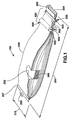
- Figure 1 illustrates an apparatus 100 for packaging and storing a moisture-sensitive product in accordance with one embodiment of the invention. While described herein primarily with respect to moisture-curable orthopedic splinting/casting products, the invention is equally applicable to most any other moisture-sensitive product.
- a sleeve or pouch 200 preferably elongate, made from a flexible and ideally moisture-impermeable material is provided.
- the pouch defines an interior space 202 which is accessed via an opening 204 located at a first end 206 of the pouch 200.
- a sheet of continuous length orthopedic splinting/casting product 300 (which is hereinafter referred to as "product" 300) is located within the interior 202.
- product 300 is folded so that, although it may have an unfolded length substantially greater than the length of the pouch 200, it fits easily therein when folded into a packaged configuration as shown.
- an optional closure system 400 may also be provided and shown in Figure 1.
- the closure system includes a sealing device 500 (further described herein) and a compression device 600 (also further described herein).
- the closure device 500 and compression device 600 may be separate components as illustrated in Figure 1 or, alternatively, may be combined to form an integrated closure system 400 as further described below.
- the sealing device 500 is located proximate the pouch opening 204 to permit substantially hermetic sealing of the opening 204 during storage, i.e., when the product 300 is not being dispensed.
- the compression device 600 is similarly located proximate the opening 204 and is provided to reduce moisture intrusion during dispensing of the product 300 and may further reduce moisture intrusion when the sealing device 500 is closed.
- the pouch 200 (see Figure 1) of the present invention may be manufactured using one piece of material, preferably a moisture-impervious material, folded over and heat sealed along the mating edges to form what is commonly referred to as a standard fin seal. Alternatively, two pieces of material may be heat-sealed together along their peripheral edges.
- One preferred packaging material for the pouch 200 is a laminate with an outer layer of polypropylene over a layer of polyethylene over a layer of aluminum foil.
- the innermost layer is preferably SURLYNTM ionomer resin available from E.I. DuPont de Nemours & Company, Wilmington, Del., or, alternatively, a form of polyethylene to provide sufficient heat sealing properties.
- the pouch 200 may be formed with gussets (not shown) that permit the pouch 200 to expand more readily to accept the product 300.
- gussets are generally discussed in U.S. Patent No. 5,505,305.
- the pouch has a pouch length 205 (see Figure 1) measured between the first end 206 and a second end 207. While shown and described herein as an elongate pouch having a constant width 210, pouches of most any shape are contemplated. For example, a pouch 200 having a length 205 equal to its width 210 or, alternatively, a pouch having a variable width along the length is possible without departing from the scope of the invention. In one exemplary embodiment, the pouch is generally rectangular in the plan view and has a length 205 at least two times the pouch width 210. Still other pouch configurations can be produced to correspond to the desired product to be stored therein.
- Figure 2 illustrates a cut-away view of the apparatus 100.
- the folded product 300 is shown within the interior 202 of the pouch 200.
- the present invention folds the product into distinct, repeating sections 302 each having a length 304.
- the product 300 may preferably fit into a generally flat pouch, e.g., a pouch that, when empty, forms a generally flat sheet.
- the flat pouch configuration is advantageous due to its relatively simple and cost-effective construction. However, pouches of most any shape are possible without departing from the scope of the invention.
- each section 302 includes a generally linear segment 302b spanning between two folds 306a and 306b.
- connecting segments 302a and 302c form the remainder of the S-shaped section 302.
- While the method used to fold the product 300 can be adapted to take advantage of specific manufacturing equipment or processes, it includes, in one embodiment, first positioning the product 300 to form connecting segment 302a. The product is then folded back on itself along fold 306a to form segment 302b. The product 300 is then folded back on itself again along fold 306b to form connecting segment 302c. Connecting segment 302c then connects to the beginning of connecting segment 302a of the next section (see Figure 2) after which the S-shaped sections may repeat.
- the product 300 is illustrated in the following figures with exaggerated separation between adjacent sections and segments (e.g., gaps between segments 302a/302b and 302b/302c).
- the segments may physically contact one another.
- an end user simply pulls on the end of the product accessible through the opening 204 (with the closure device 500 open or otherwise removed). Since the segments 302a, 302b, 302c are generally aligned with the pulling direction 306 (see Figure 2), the product 300 tends to unfold and egress more easily from the pouch than if the segments were otherwise oriented. Further, by orienting the segments 302a, 302b, and 302c along the length of the pouch 200, e.g., parallel with the pouch, a favorable (i.e., smaller) pouch height and length are achieved.
- sectioned, folding pattern of the present invention includes, for instance, reduced frictional resistance during dispensing. This is attributable to the fact that the sections 302 provide less product surface in contact during dispensing than some other folding configurations such as the full-length fan-fold shown in Figure 3B. Further, fold configurations like that described in Figure 3A provide only a small portion of the product 300 proximate the opening 204 (see e.g., Figure 2). Thus, premature curing of the product 300 due to inadvertent exposure via the opening 204 is limited to only that portion proximate thereto.
- FIG. 3B may have numerous folds near the opening, increasing the risk of premature curing of portions of the product 300' along its entire length. In some instances, moisture intrusion into the pouch 200' may necessitate disposal of the entire product 300'.
- the folding patterns are frequently defined herein without regard to the connecting segments (e.g., those segments such as 302a and 302c that interconnect one section 302 to the next).
- the folding configuration illustrated in Figure 3A is said to include one segment 302b bounded by folds 306a and 306b. It is understood that, because each section 302 forms part of a continuous length of product 300, the connecting segments 302a and 302c are included by necessity. Accordingly, the following discussion may exclude specific reference to the connecting segments except where necessary to clarify the invention.
- FIG. 4 and 5A Another example of a packaged configuration in accordance with the present invention is shown in Figures 4 and 5A.
- the folding arrangement illustrated in these figures like that shown in Figures 2 and 3, provides discrete sections having segments extending along the length of the pouch 200.
- the product 300 is folded in a repeating series of mushroom-shaped sections 302' each having a length 304'.
- Figure 5A illustrates each section 302' having three segments 302b', 302c', and 302d' wherein each of these segments is bounded by folds. Segment 302b' is bounded by folds 306a' and 306b', segment 302c' is bounded by folds 306b' and 306c', and segment 302d' is bounded by folds 306c' and 306d'.
- Connecting segments 302a' and 302e' span between and connect adjacent sections.
- the sections 302' are, in one embodiment, formed by first positioning a connecting segment 302a' as shown in Figure 5A.
- segment 302b' which is preferably equal in length to connecting segment 302a'.
- the product 300 is then folded over onto itself again along fold 306b' to form segment 302c' which, in one embodiment, is approximately twice as long as segment 302b'.
- the product is thereafter folded under itself along fold 306c' to form segment 302d' and folded under itself again along fold 306d' to form connecting segment 302e' as shown.
- Segments 302d' and 302e' are approximately equal in length to segments 302b' and 302a', respectively.
- Figure 5B illustrates yet another packaged configuration in accordance with the present invention.
- the section 310 of Figure 5B has a length 314 and includes three segments 310b, 310c, and 310d each bounded by folds 312a and 312b, 312b and 312c, and 312c and 312d, respectively.
- Connecting segments 310a and 310e span between and connect adjacent sections 310.
- the embodiment of Figure 5B yields a packaged configuration approximately one fifth the length of the unfolded product 300.
- each section preferably has an unfolded length that corresponds to a common splinting/casting size.
- each section may have an unfolded length of about 30 inches to about 60 inches (75-150 centimeters).
- the pouch size is preferably selected to enclose a convenient number of sections.
- the continuous length product 300 is about 12 to about 15 feet (3.5-4.5 meters) long and folded into three to six sections so that it fits within a pouch 200 that ranges from about 2 to about 5 feet (0.5-1.5 meters) long.
- the ratio of the product length to the pouch length is about 2:1 or more and more preferably about 3:1 or more.
- the pouch itself may further be folded, preferably once, to fit within a shipping or storage box that is about 10 to about 30 inches (25-75 centimeters) long. Of course, other pouch and box sizes are also contemplated.
- Figures 3B and 5C-5E show a product in a horizontal fan-fold.
- Figure 5C illustrates a product having rolled sections;
- Figure 5D shows a product folded in a tilted fan-fold;
- Figure 5E shows a product folded in a vertical fan-fold.
- the apparatus 100 may be suspended such that the opening 204 (see Figure 1) is at a lower elevation than the second end 207.
- the pouch 200 may include a suspension member, e.g., an eyelet 208 (also shown in Figure 1) or a hook (not shown).
- the suspension feature is located on the pouch, e.g., at the second end 207 opposite the opening 204, and is adapted to support the apparatus 100 from a corresponding hanging feature, e.g., hook (not shown) or the like.
- the pouch may be draped over a rod.
- the closure system 400 in addition to its other uses as described below, prevents the product 300 from falling out of the pouch when the latter is vertically positioned.
- the apparatus 100 may preferably include the optional closure system 400.
- One purpose of the closure system 400 is to permit sealing of the opening 204, thus reducing moisture intrusion into the interior 202 of the pouch 200.
- a sealing device 500 is provided.
- the sealing device 500 is placed over the first end 206 of the pouch 200 and, when in a closed configuration, clamps shut or otherwise substantially hermetically seals the opening 204. While most any device capable of sealing the pouch is possible, one exemplary embodiment is shown in Figure 1.
- the device 500 includes two elongate elements 502 that span across the top and bottom of the pouch 200 proximate the opening 204.
- the ends of the elements 502 include a fastening device, e.g., clip or fastener, which permits tightening of the elements relative to one another.
- proximate ends of the opposing elements 502 may be coupled, e.g., hinged, to secure the two elements to one another.
- the device 500 in another embodiment, includes interengaging teeth (see Figure 2).
- Other devices that permit substantial sealing of the pouch are also possible including for example, biased (magnetic, spring-loaded, etc.) clamps, tongue and groove scissors clamps, moisture-proof adhesive tapes, spring-loaded compression gaskets, leverage clamps, screw action devices, ZIPLOCKTM - type seals, etc.
- the closure system 400 preferably includes a compression device 600 of which one embodiment is diagrammatically illustrated in Figures 1 and 2.
- the compression device 600 illustrated in these figures is configured as two opposing compression members, e.g., cylinders 602, which substantially conform the shape of the first end 206 of the pouch 200 to the shape of the product 300. Conformance occurs by urging the walls of the pouch 200 against the product 300 under the compressive force of the members 602.
- Figures 6 and 7 provide a more detailed view of a compression device 600 according to one embodiment of the invention.
- the members 602 preferably include or are made from compressible material.
- the compressible material permits deformation of the members 602 (see Figure 7) such that sealing around the periphery of the product 300 is achieved.
- only one of the members 602 may be compressible, although it is preferred that both members 602 are compressible.
- the members 602 can be made of most any compressible material, they are, in one embodiment, made of low density foam pads. Low density foam provides a member having a high compression ratio which, in turn, allows the members to deform and better conform to the contours of the product 300.
- the pads which form the members 602, as further explained below, are not limited to cylindrically shaped elements but may be most any shape.
- the members 602 preferably extend outwardly beyond the transverse edges of the product (see Figure 7). This construction permits the members 602 to better wrap around the transverse edges and minimize the gap 606 available for moisture entry.
- the device 600 may include side compression members (not shown) that, similar to members 602, apply a transverse compressive load to seal against the side edges of the product.
- the contour conformance illustrated in Figure 7 can be achieved in a variety of ways. For instance, a uniform diameter member 602 may be pressed against the pouch 200 with sufficient force to deform as shown. In another embodiment, the members 602 may be somewhat less compressible but have a stepped profile (similar to that shown in Figure 7) that conforms to the shape of the product. Still further, the members 602 may achieve conformance through a combination of material selection (e.g., low density foam) and contoured (e.g., stepped) construction.
- material selection e.g., low density foam
- contoured e.g., stepped
- each member 602 preferably includes a rigid or semi-rigid member, e.g., core 604, to which the member 602 is formed or otherwise attached.
- the core 604 ensures that the members 602 provide the desired compression across their length.
- the cores 604 also preferably include a structural feature that permits connecting of the proximate ends of opposing cores 604.
- the structural feature is merely an extended portion of the core, e.g., a tip portion 605, attached to or integral with each end of the core 604.
- the core 604 is shown as a unitary member, other embodiments are also possible, e.g., an axle and/or bearings, multiple cores, external support members instead of cores, etc.
- a tension member is provided to bias the members 602 towards one another.
- the tension member is a dynamically elastic component 608, e.g., a rubber band or spring, as diagrammatically shown in Figure 7.
- the tension member may also be configured as a semi-rigid, rigid, or other elastic member.
- the length and compliance of the tension members 608, the compliance of the members 602, and other factors determine the deformation of the members 602. These variables are preselected to ensure that the members 602 substantially conform to the contours of the product 300 and further to ensure the desired preload is applied.
- the compression device 600 is positioned external to the pouch proximate the first end 206 as shown in Figure 1.
- the product 300 is positioned so that it extends between the members 602 (as shown in Figures 2 and 6).
- the device 600 e.g., the tension member 608, may be adjusted to increase or decrease the desired compression of the members 602.
- the product is cut and the remaining product is pushed back into the pouch so that the sealing device 500 may be closed.
- the pouch may also be cut in conjunction with the product.
- the compression device 600 may be moved along the length of the pouch as required to maintain proximity with the opening 204.
- the device 600 may include other devices, e.g., a clamp (not shown), to selectively secure the device 600 along the length of the pouch 200.
- the compression device 600 In addition to conforming the pouch 200 to the product 300, the compression device 600 also tends to smooth the product 300 during dispensing. That is, as the product is dispensed, it is squeezed between the members 602. This squeezing action may result in removal of wrinkles and/or tend to straighten folds formed in the product 300. To increase the smoothing effect, the length of the members 602 along the pouch, e.g., the length of contact between the members 602 and the product 300, may be increased.
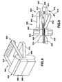
- FIGS. 8 and 9 illustrate a closure apparatus 800 that includes a fixed frame having a compression device 802 and sealing device 804.
- the compression device 802 includes two compression members 806 that, in this exemplary embodiment, are rectangular in shape (see Figure 9). However, other cross-sectional shapes including but not limited to, oval, circular and polygonal shapes are also possible without departing from the scope of the invention.
- a frame assembly 808 couples the members 806 to one another. While not shown, the frame assembly 808 may include cores similar to cores 604 illustrated in Figure 7 to support the members 806 or, alternatively, may externally support the members 806. In still another embodiment, the members 806 may be adhesively attached to the frame assembly 808. Extending away from the frame assembly 808 are arm members 810 and 812 which, at their distal ends, form the sealing device 804, preferably having interengaging teeth 814. To engage the teeth 814 and seal the pouch 200, the member 812 pivots about the assembly 808 as generally indicated by arrow 816 in Figure 9. When the member 812 is pivoted in the direction 816, the pouch 200 is pinched between the teeth 814, effectively sealing the first opening 204. To open the sealing device 804, the member 812 is pivoted in a second direction as indicated by arrow 818 in Figure 9.
- the member 812 can be configured in a variety of ways. For instance, the member 812 may be biased (either in the direction 816 or 818) about the assembly 808. In another embodiment, the member 812 is plasticly deformable about the assembly 808 in the directions 816 and 818 by the application of sufficient force. In still other embodiments, the apparatus 800 includes additional hardware, e.g., clips, or fasteners, adapted to secure the member 812 relative to the member 810 (e.g., hold the sealing device closed or open).
- additional hardware e.g., clips, or fasteners
- the apparatus 800 is placed onto the first end 206 of the pouch 200 and positioned so that the product 300 is between the members 806 (see Figure 9).
- the members 806 are preferably foam or a similar compressible material so that the members 806 substantially conform to the shape of the product 300 (see e.g., Figure 7). Further, the members 806 preferably extend beyond the width of the product (see Figure 7) to allow better sealing around the transverse edges.
- the member 812 can be manipulated to close and seal the pouch.
- the member 812 is moved in the direction 818 and the product is pulled in the direction 820.
- the remaining product can be tucked back into the opening 204 a sufficient distance to allow the sealing device 804 to seal the pouch 200. That is, the product 300 may be pushed back into the pouch 200 as shown in Figure 9 so that the member 812 may be manipulated in the direction 816 to seal the opening 204 without interference from the product 300.
- the pouch 200 may be cut with the product in which case the device 800 can be relocated along the pouch length to maintain the desired proximity to the opening 204.
- Figures 10 and 11 illustrate yet another embodiment of a closure apparatus 900.
- the apparatus 900 includes both a compression device 902 and a sealing device 904.
- the apparatus 900 is configured to somewhat resemble a conventional clothes pin.
- the compression members 906, are biased towards one another by a torsion spring or other biasing member 908.
- Extending away from the compression device 902 are members 910 and 912.
- the distal ends of the members 910 and 912 form the sealing device 904.
- the sealing device 904 in one embodiment, includes interengaging members, e.g., teeth 914. To seal the pouch, the member 910 is moved in the direction 918 (see Figure 11).
- the member 910 is moved in the direction 916 (see Figure 11).
- movement of the member 910 is accomplished by plastic deformation, e.g., bending of the member 910.
- other embodiments where the members 910 and 912 move relative to one another by other methods, e.g., pivoting of the member 910 about an axis 922, are also possible.
- the apparatus 900 operates substantially like the apparatus 800 illustrated in Figures 8 and 9.
- the sealing device is opened and the product is pulled in the direction 920 (see Figure 11).
- the members 906, which are preferably pads made of foam or another compressible material, conform to the shape of the product under the biasing load of the spring 908.
- the sealing device 904 may be closed, e.g., the member 910 moved in the direction 918.
- the pouch may also be pulled between the members 906 so that it may be cut and shortened as the product is dispensed.
- the apparatus 900 may be moved along the length of the pouch as required to maintain proximity with the opening 204.
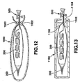
- Figures 12-20 illustrate still other embodiments for storing and dispensing product 300 in accordance with the present invention.
- Figure 12 shows a pouch 200 containing product 300 as already described herein.
- the pouch 200 in this embodiment is further enclosed within a container 1000.
- the container 1000 is advantageous for several reasons such as providing greater protection to the pouch during shipping and storage.
- the container is preferably formed from a rigid or semi-rigid material such as plastic, metal, or cardboard.
- Integral with or otherwise coupled to the container 1000 are compression members 1002 which, like the compression members 602, 806, and 906 described above, are compressible and adapted to conform to the shape of the product 300.
- the container 1000 may include features, e.g., fasteners, suction cups, velcro, etc. (not shown), which permit attachment of the container 1000 to a counter or wall.
- a sealing device 500 as already described herein is also included.
- Figure 13 illustrates the pouch 200 (holding product 300) in a container 1100 similar to the container 1000.
- the container may be formed from a conventional shipping container, e.g., a cardboard box.
- the box 1100 includes compression members 1102 that are coupled to the box and apply the desired compressive load to seal the interior of the pouch from ambient conditions.
- a sealing device 500 is also included.
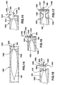
- Figures 14 and 15 illustrate a container 1200 in accordance with yet another embodiment of the invention. While the container 1200 is substantially similar to the container 1100 of Figure 13 in many respects (see e.g., compression members 1102 and 1202), the container 1200 further includes an integral sealing device 1204.
- the device 1204 includes, in one embodiment, an L-shaped member 1205 which pivots between a closed position which seals the first opening 204 of the pouch 200 (see Figure 14) and an open position which provides access to the first opening (see Figure 15).
- a retaining feature such as a flexible lip 1206 is included.
- the L-shaped member 1205 pivots about a pivot axis 1207.
- the pivot axis 1207 can be an actual hinged joint or alternatively, it can be a weakened portion of the container 1200 (e.g., a fold line in a cardboard box or a thinned section in a plastic container). In any event, the L-shaped member 1205 is movable in the direction 1208 to permit opening and sealing of the pouch 200.
- Figures 16 and 17 illustrate yet additional embodiments of the invention.
- Figure 16 illustrates a container 1300 similar in most respects to the container 1200 of Figures 14 and 15 (see e.g., compression members 1302).
- the embodiment illustrated in Figure 16 replaces the L-shaped member 1205 with a guillotine-style sealing device 1305.
- the sealing device 1305 includes a slide member 1306 which rides within a guide slot 1307 formed by parallel portions of the container 1300. When the slide is raised (as shown in Figure 16), access to the interior of the pouch is provided via the opening 204 and container aperture 1303. However, when the slide 1306 is displaced in the direction 1308, the slide traps the pouch 200 between the slide and a clamp surface, e.g., interior surfaces of the slot 1307, sealing the pouch 200.
- Figure 17 illustrates a container 1400 modified slightly from the container 1300 of Figure 16.
- a slide member 1406 when closed, pinches the pouch 200 against an opposing clamp surface 1409.
- the slide may engage the slot 1407 (or 1307) with an interference fit.
- the slide 1406 (or 1306) and the portions of the container that define the slot may be coated or reinforced to provide improved stiffness and wear resistance.
- Figure 17 further illustrates compression members 1402.
- the compression members are cardboard extensions of a cardboard container 1400 rather than separate foam or other compressible material attached to the container. By sizing the cardboard extensions appropriately, the desired compression force may be applied against the product within the pouch 200.
- Figure 18 illustrates yet another embodiment of a container 1500.
- the container 1500 includes an independent compression device 600 (similar to that shown in Figures 6 and 7) and an independent sealing device 1600.
- the device 600 may be coupled to the pouch 200 before placement of the pouch into the container 1500.
- the sealing device 1600 includes a female member 1602 and a male member 1604.
- the male member 1604 is aligned with the female member 1602 and the two components are forced together in the direction 1606 as shown in Figure 18, trapping the pouch 200 therebetween. With the pouch trapped, the female member 1602 and the male member are engaged in an interference fit.
- the sealing device 1600 includes an interconnecting member (not shown) which couples the members 1602 and 1604 to one another.
- sealing devices 804 are parallel closure devices. That is, these sealing devices seal across the width of the pouch simultaneously as opposed to scissors or zipper-type clamps in which the sealing members close gradually across the pouch width.
- Parallel closure devices may provide a more uniform seal and generally result in reduced bunching and creasing of the pouch proximate the sealing area. Nonetheless, other parallel and non-parallel sealing devices may be used without departing from the scope of the invention.
- the pouch may include a pocket 1700, an example of which is illustrated in Figure 20.
- the pocket 1700 is formed by a member 1702 that is preferably attached to the pouch 200.
- the pocket 1700 protects the product 300 by providing yet another barrier between the product 300 and the ambient environment. While illustrated with only one pocket and simple S-shaped sections, the pocket 1700 may also accommodate other repeating sections such as the mushroom-shaped sections described above or even simple fan-folded products.
- a pouch having numerous pockets 1700 to accept individual sections, e.g., sections 302 of Figure 2 is also contemplated.
- compression devices and sealing devices described herein are also exemplary. Any of the above-described compression devices or their equivalents may be interchanged with most any of the sealing devices described herein (or equivalents) to produce yet additional closure systems.
- the present invention provides apparatus and methods for storing continuous length, moisture-sensitive products within flexible pouches.
- resistance to product removal is substantially reduced.
- the folding patterns of the present invention further reduce curing due to inadvertent exposure to ambient conditions.
- the folding patterns described herein allow storage of product within an economical pouch having reduced length.
- the present invention also provides closure systems that permit substantial sealing of the pouch before, during, and after dispensing of the product.
Landscapes
- Engineering & Computer Science (AREA)
- Mechanical Engineering (AREA)
- Health & Medical Sciences (AREA)
- Animal Behavior & Ethology (AREA)
- Public Health (AREA)
- Heart & Thoracic Surgery (AREA)
- Vascular Medicine (AREA)
- Life Sciences & Earth Sciences (AREA)
- Epidemiology (AREA)
- General Health & Medical Sciences (AREA)
- Biomedical Technology (AREA)
- Veterinary Medicine (AREA)
- Packages (AREA)
- Packaging Of Annular Or Rod-Shaped Articles, Wearing Apparel, Cassettes, Or The Like (AREA)
- Bag Frames (AREA)
- Orthopedics, Nursing, And Contraception (AREA)
- Packging For Living Organisms, Food Or Medicinal Products That Are Sensitive To Environmental Conditiond (AREA)
Applications Claiming Priority (3)
| Application Number | Priority Date | Filing Date | Title |
|---|---|---|---|
| US551706 | 2000-04-18 | ||
| US09/551,706 US6981590B1 (en) | 2000-04-18 | 2000-04-18 | Apparatus and methods for packaging and storing moisture-sensitive products in resealable pouches |
| PCT/US2000/026792 WO2001078640A1 (en) | 2000-04-18 | 2000-09-28 | Apparatus and methods for packaging and storing moisture-sensitive products in resealable pouches |
Publications (2)
| Publication Number | Publication Date |
|---|---|
| EP1276448A1 EP1276448A1 (en) | 2003-01-22 |
| EP1276448B1 true EP1276448B1 (en) | 2005-02-16 |
Family
ID=24202346
Family Applications (1)
| Application Number | Title | Priority Date | Filing Date |
|---|---|---|---|
| EP00970513A Expired - Lifetime EP1276448B1 (en) | 2000-04-18 | 2000-09-28 | Apparatus and methods for packaging and storing moisture-sensitive products in resealable pouches |
Country Status (9)
| Country | Link |
|---|---|
| US (1) | US6981590B1 (enExample) |
| EP (1) | EP1276448B1 (enExample) |
| JP (1) | JP2004510640A (enExample) |
| KR (1) | KR20020089480A (enExample) |
| AT (1) | ATE289188T1 (enExample) |
| AU (1) | AU2000279882A1 (enExample) |
| CA (1) | CA2403268A1 (enExample) |
| DE (1) | DE60018220D1 (enExample) |
| WO (1) | WO2001078640A1 (enExample) |
Families Citing this family (7)
| Publication number | Priority date | Publication date | Assignee | Title |
|---|---|---|---|---|
| DE10361306A1 (de) * | 2003-12-24 | 2005-07-28 | Lts Lohmann Therapie-Systeme Ag | Wundauflage und Wundschnellverband mit einem vasokonstriktorischen Inhaltsstoff, sowie Herstellungsverfahren hierfür |
| US20070232971A1 (en) * | 2006-03-30 | 2007-10-04 | Stanton John L | Padded orthopaedic splint device |
| US7694816B2 (en) * | 2007-01-05 | 2010-04-13 | Kilbey Bryan E | Dispenser system with seal on sliding door |
| US7748531B2 (en) * | 2007-10-04 | 2010-07-06 | Bsn Medical, Inc. | Medical bandaging product |
| US8424683B2 (en) * | 2008-10-31 | 2013-04-23 | Kimberly-Clark Worldwide, Inc. | Portable rolled wiping product |
| US8529422B2 (en) | 2010-12-03 | 2013-09-10 | Disc Graphics, Inc. | Apparatus for manufacturing of packaging container with reclosable connection |
| US12338058B2 (en) * | 2022-01-12 | 2025-06-24 | Peel Plastic Products Ltd | Wipes bag |
Family Cites Families (20)
| Publication number | Priority date | Publication date | Assignee | Title |
|---|---|---|---|---|
| BE542694A (enExample) | ||||
| CH265688A (de) | 1948-04-22 | 1949-12-15 | Siegenheim Max | Gebrauchspackung, welcher nicht aus Textilmaterial bestehende Tücher entnommen werden können. |
| US2834459A (en) * | 1956-06-05 | 1958-05-13 | Kimberly Clark Co | Absorbent dressing package |
| GB971552A (en) | 1960-12-06 | 1964-09-30 | Smith & Nephew | Improvements in and relating to plaster of paris bandages,containers and dispensers therefor |
| US3629905A (en) * | 1970-06-17 | 1971-12-28 | Delmer J Cote | Bread bag resealer |
| US4002264A (en) * | 1975-01-30 | 1977-01-11 | Colgate-Palmolive Company | Dispensing means for moist tissues |
| US4609578A (en) | 1984-11-06 | 1986-09-02 | Minnesota Mining And Manufacturing Company | Resin-coated extensible heat-set fiberglass knit tape |
| US4703518A (en) * | 1985-08-27 | 1987-10-27 | Minigrip, Inc. | Attachment of plastic zipper to the outside of incompatible bag wall web |
| US4667661A (en) | 1985-10-04 | 1987-05-26 | Minnesota Mining And Manufacturing Company | Curable resin coated sheet having reduced tack |
| US4899738A (en) | 1987-01-06 | 1990-02-13 | Parker A Bruce | Roll form medical bandaging product |
| US5003970B1 (en) | 1987-01-06 | 1999-07-27 | Smith & Nephew Castling Inc | Roll form medical bandaging product method of constructing same and container for roll from bandaging product |
| US4869046A (en) | 1987-01-06 | 1989-09-26 | Parker A Bruce | Roll form medical bandaging product and method of constructing same |
| US4770299A (en) | 1987-01-06 | 1988-09-13 | Parker Medical Associates | Roll form medical bandaging product |
| US5027803A (en) | 1988-07-22 | 1991-07-02 | Minnesota Mining & Manufacturing Company | Orthopedic splinting and casting article |
| DE68913893T2 (de) * | 1988-10-15 | 1994-08-18 | Kenji Nakamura | Ausgabebehälter für feuchte Tücher, Verfahren zur Herstellung desselben und Vorrichtung hierfür. |
| US5405629A (en) * | 1990-04-05 | 1995-04-11 | Oscar Mayer Foods Corporation | Multi-seal reclosable flexible package for displaying thinly sliced food products |
| US5505305A (en) | 1992-10-21 | 1996-04-09 | Minnesota Mining And Manufacturing Company | Moisture-proof resealable pouch and container |
| US5716661A (en) | 1993-04-16 | 1998-02-10 | Minnesota Mining And Manufacturing Company | Method of making a light weight orthopedic casting tape |
| EP0796210A1 (en) | 1995-01-03 | 1997-09-24 | Minnesota Mining And Manufacturing Company | Flexible dispenser and method for dispensing sorbent nonwoven webs containing microfibers |
| US5622431A (en) * | 1995-06-26 | 1997-04-22 | Reynolds Consumer Products Inc. | External zipper clip for a bag |
-
2000
- 2000-04-18 US US09/551,706 patent/US6981590B1/en not_active Expired - Fee Related
- 2000-09-28 DE DE60018220T patent/DE60018220D1/de not_active Expired - Lifetime
- 2000-09-28 JP JP2001575943A patent/JP2004510640A/ja not_active Withdrawn
- 2000-09-28 KR KR1020027013886A patent/KR20020089480A/ko not_active Withdrawn
- 2000-09-28 AT AT00970513T patent/ATE289188T1/de not_active IP Right Cessation
- 2000-09-28 WO PCT/US2000/026792 patent/WO2001078640A1/en not_active Ceased
- 2000-09-28 AU AU2000279882A patent/AU2000279882A1/en not_active Abandoned
- 2000-09-28 EP EP00970513A patent/EP1276448B1/en not_active Expired - Lifetime
- 2000-09-28 CA CA002403268A patent/CA2403268A1/en not_active Abandoned
Also Published As
| Publication number | Publication date |
|---|---|
| EP1276448A1 (en) | 2003-01-22 |
| AU2000279882A1 (en) | 2001-10-30 |
| DE60018220D1 (de) | 2005-03-24 |
| US6981590B1 (en) | 2006-01-03 |
| ATE289188T1 (de) | 2005-03-15 |
| WO2001078640A1 (en) | 2001-10-25 |
| CA2403268A1 (en) | 2001-10-25 |
| JP2004510640A (ja) | 2004-04-08 |
| KR20020089480A (ko) | 2002-11-29 |
Similar Documents
| Publication | Publication Date | Title |
|---|---|---|
| US6022144A (en) | Closure system for pliable container and method and apparatus for producing same | |
| MXPA02006284A (es) | Bolsa de hielo con abertura expandible. | |
| US20030102239A1 (en) | Packaging and dispensing system for pouched products | |
| EP1321381B1 (en) | Package for compressible products and method of making the package | |
| US5020670A (en) | Shipping carton and dipsenser for sponge articles | |
| US20010037627A1 (en) | Closure system for a pliable container | |
| US4317478A (en) | Self-closing, snap-open pouch and method of making same | |
| EP1276448B1 (en) | Apparatus and methods for packaging and storing moisture-sensitive products in resealable pouches | |
| JP2008504184A (ja) | 医療で使用するための製品を収容した包体のマルチパッケージ | |
| US10543134B2 (en) | Band-fastened convenience-packaging for storing absorbent personal care articles | |
| JP2010540158A (ja) | 医療用の包帯製品 | |
| JP2000505027A (ja) | 圧縮可能な製品の改良包装体およびその製造方法 | |
| US20070239127A1 (en) | Disposal wrapper for used feminine products | |
| BR112013013687B1 (pt) | Embalagem destinada ao consumidor | |
| JP3257296B2 (ja) | 紙 袋 | |
| JPH0231413Y2 (enExample) | ||
| ITTV20080090A1 (it) | Sacchetto per il pattume con dispositivo legaccio di chiusura e metodo di chiusura e produzione del sacchetto. | |
| JPH0110363Y2 (enExample) | ||
| JPH0133476Y2 (enExample) | ||
| JP2687208B2 (ja) | 切り花用保水袋 | |
| JP2002284268A (ja) | 梱包長尺物 |
Legal Events
| Date | Code | Title | Description |
|---|---|---|---|
| PUAI | Public reference made under article 153(3) epc to a published international application that has entered the european phase |
Free format text: ORIGINAL CODE: 0009012 |
|
| 17P | Request for examination filed |
Effective date: 20021115 |
|
| AK | Designated contracting states |
Kind code of ref document: A1 Designated state(s): AT BE CH CY DE DK ES FI FR GB GR IE IT LI LU MC NL PT SE |
|
| AX | Request for extension of the european patent |
Free format text: AL;LT;LV;MK;RO;SI |
|
| 17Q | First examination report despatched |
Effective date: 20031111 |
|
| GRAP | Despatch of communication of intention to grant a patent |
Free format text: ORIGINAL CODE: EPIDOSNIGR1 |
|
| GRAS | Grant fee paid |
Free format text: ORIGINAL CODE: EPIDOSNIGR3 |
|
| GRAA | (expected) grant |
Free format text: ORIGINAL CODE: 0009210 |
|
| AK | Designated contracting states |
Kind code of ref document: B1 Designated state(s): AT BE CH CY DE DK ES FI FR GB GR IE IT LI LU MC NL PT SE |
|
| PG25 | Lapsed in a contracting state [announced via postgrant information from national office to epo] |
Ref country code: IT Free format text: LAPSE BECAUSE OF FAILURE TO SUBMIT A TRANSLATION OF THE DESCRIPTION OR TO PAY THE FEE WITHIN THE PRESCRIBED TIME-LIMIT;WARNING: LAPSES OF ITALIAN PATENTS WITH EFFECTIVE DATE BEFORE 2007 MAY HAVE OCCURRED AT ANY TIME BEFORE 2007. THE CORRECT EFFECTIVE DATE MAY BE DIFFERENT FROM THE ONE RECORDED. Effective date: 20050216 Ref country code: LI Free format text: LAPSE BECAUSE OF FAILURE TO SUBMIT A TRANSLATION OF THE DESCRIPTION OR TO PAY THE FEE WITHIN THE PRESCRIBED TIME-LIMIT Effective date: 20050216 Ref country code: FI Free format text: LAPSE BECAUSE OF FAILURE TO SUBMIT A TRANSLATION OF THE DESCRIPTION OR TO PAY THE FEE WITHIN THE PRESCRIBED TIME-LIMIT Effective date: 20050216 Ref country code: NL Free format text: LAPSE BECAUSE OF FAILURE TO SUBMIT A TRANSLATION OF THE DESCRIPTION OR TO PAY THE FEE WITHIN THE PRESCRIBED TIME-LIMIT Effective date: 20050216 Ref country code: FR Free format text: LAPSE BECAUSE OF NON-PAYMENT OF DUE FEES Effective date: 20050216 Ref country code: BE Free format text: LAPSE BECAUSE OF FAILURE TO SUBMIT A TRANSLATION OF THE DESCRIPTION OR TO PAY THE FEE WITHIN THE PRESCRIBED TIME-LIMIT Effective date: 20050216 Ref country code: ES Free format text: LAPSE BECAUSE OF FAILURE TO SUBMIT A TRANSLATION OF THE DESCRIPTION OR TO PAY THE FEE WITHIN THE PRESCRIBED TIME-LIMIT Effective date: 20050216 Ref country code: AT Free format text: LAPSE BECAUSE OF FAILURE TO SUBMIT A TRANSLATION OF THE DESCRIPTION OR TO PAY THE FEE WITHIN THE PRESCRIBED TIME-LIMIT Effective date: 20050216 Ref country code: CH Free format text: LAPSE BECAUSE OF FAILURE TO SUBMIT A TRANSLATION OF THE DESCRIPTION OR TO PAY THE FEE WITHIN THE PRESCRIBED TIME-LIMIT Effective date: 20050216 |
|
| REG | Reference to a national code |
Ref country code: GB Ref legal event code: FG4D |
|
| REG | Reference to a national code |
Ref country code: CH Ref legal event code: EP |
|
| REG | Reference to a national code |
Ref country code: IE Ref legal event code: FG4D |
|
| REF | Corresponds to: |
Ref document number: 60018220 Country of ref document: DE Date of ref document: 20050324 Kind code of ref document: P |
|
| PG25 | Lapsed in a contracting state [announced via postgrant information from national office to epo] |
Ref country code: GR Free format text: LAPSE BECAUSE OF FAILURE TO SUBMIT A TRANSLATION OF THE DESCRIPTION OR TO PAY THE FEE WITHIN THE PRESCRIBED TIME-LIMIT Effective date: 20050516 Ref country code: DK Free format text: LAPSE BECAUSE OF FAILURE TO SUBMIT A TRANSLATION OF THE DESCRIPTION OR TO PAY THE FEE WITHIN THE PRESCRIBED TIME-LIMIT Effective date: 20050516 Ref country code: SE Free format text: LAPSE BECAUSE OF FAILURE TO SUBMIT A TRANSLATION OF THE DESCRIPTION OR TO PAY THE FEE WITHIN THE PRESCRIBED TIME-LIMIT Effective date: 20050516 |
|
| PG25 | Lapsed in a contracting state [announced via postgrant information from national office to epo] |
Ref country code: DE Free format text: LAPSE BECAUSE OF FAILURE TO SUBMIT A TRANSLATION OF THE DESCRIPTION OR TO PAY THE FEE WITHIN THE PRESCRIBED TIME-LIMIT Effective date: 20050518 |
|
| PG25 | Lapsed in a contracting state [announced via postgrant information from national office to epo] |
Ref country code: PT Free format text: LAPSE BECAUSE OF FAILURE TO SUBMIT A TRANSLATION OF THE DESCRIPTION OR TO PAY THE FEE WITHIN THE PRESCRIBED TIME-LIMIT Effective date: 20050721 |
|
| NLV1 | Nl: lapsed or annulled due to failure to fulfill the requirements of art. 29p and 29m of the patents act | ||
| REG | Reference to a national code |
Ref country code: CH Ref legal event code: PL |
|
| PG25 | Lapsed in a contracting state [announced via postgrant information from national office to epo] |
Ref country code: CY Free format text: LAPSE BECAUSE OF FAILURE TO SUBMIT A TRANSLATION OF THE DESCRIPTION OR TO PAY THE FEE WITHIN THE PRESCRIBED TIME-LIMIT Effective date: 20050928 Ref country code: IE Free format text: LAPSE BECAUSE OF NON-PAYMENT OF DUE FEES Effective date: 20050928 |
|
| PG25 | Lapsed in a contracting state [announced via postgrant information from national office to epo] |
Ref country code: MC Free format text: LAPSE BECAUSE OF NON-PAYMENT OF DUE FEES Effective date: 20050930 Ref country code: LU Free format text: LAPSE BECAUSE OF NON-PAYMENT OF DUE FEES Effective date: 20050930 |
|
| PLBE | No opposition filed within time limit |
Free format text: ORIGINAL CODE: 0009261 |
|
| STAA | Information on the status of an ep patent application or granted ep patent |
Free format text: STATUS: NO OPPOSITION FILED WITHIN TIME LIMIT |
|
| 26N | No opposition filed |
Effective date: 20051117 |
|
| EN | Fr: translation not filed | ||
| REG | Reference to a national code |
Ref country code: IE Ref legal event code: MM4A |
|
| PGFP | Annual fee paid to national office [announced via postgrant information from national office to epo] |
Ref country code: GB Payment date: 20070926 Year of fee payment: 8 |
|
| GBPC | Gb: european patent ceased through non-payment of renewal fee |
Effective date: 20080928 |
|
| PG25 | Lapsed in a contracting state [announced via postgrant information from national office to epo] |
Ref country code: GB Free format text: LAPSE BECAUSE OF NON-PAYMENT OF DUE FEES Effective date: 20080928 |