EP1275966A1 - Automatic analyzer and part feeding device used for the analyzer - Google Patents
Automatic analyzer and part feeding device used for the analyzer Download PDFInfo
- Publication number
- EP1275966A1 EP1275966A1 EP00909648A EP00909648A EP1275966A1 EP 1275966 A1 EP1275966 A1 EP 1275966A1 EP 00909648 A EP00909648 A EP 00909648A EP 00909648 A EP00909648 A EP 00909648A EP 1275966 A1 EP1275966 A1 EP 1275966A1
- Authority
- EP
- European Patent Office
- Prior art keywords
- rack
- lift
- racks
- uppermost
- station
- Prior art date
- Legal status (The legal status is an assumption and is not a legal conclusion. Google has not performed a legal analysis and makes no representation as to the accuracy of the status listed.)
- Granted
Links
Images


Classifications
-
- B—PERFORMING OPERATIONS; TRANSPORTING
- B01—PHYSICAL OR CHEMICAL PROCESSES OR APPARATUS IN GENERAL
- B01L—CHEMICAL OR PHYSICAL LABORATORY APPARATUS FOR GENERAL USE
- B01L9/00—Supporting devices; Holding devices
- B01L9/54—Supports specially adapted for pipettes and burettes
- B01L9/543—Supports specially adapted for pipettes and burettes for disposable pipette tips, e.g. racks or cassettes
-
- G—PHYSICS
- G01—MEASURING; TESTING
- G01N—INVESTIGATING OR ANALYSING MATERIALS BY DETERMINING THEIR CHEMICAL OR PHYSICAL PROPERTIES
- G01N35/00—Automatic analysis not limited to methods or materials provided for in any single one of groups G01N1/00 - G01N33/00; Handling materials therefor
- G01N35/02—Automatic analysis not limited to methods or materials provided for in any single one of groups G01N1/00 - G01N33/00; Handling materials therefor using a plurality of sample containers moved by a conveyor system past one or more treatment or analysis stations
- G01N35/04—Details of the conveyor system
- G01N2035/0401—Sample carriers, cuvettes or reaction vessels
- G01N2035/0418—Plate elements with several rows of samples
- G01N2035/0425—Stacks, magazines or elevators for plates
-
- G—PHYSICS
- G01—MEASURING; TESTING
- G01N—INVESTIGATING OR ANALYSING MATERIALS BY DETERMINING THEIR CHEMICAL OR PHYSICAL PROPERTIES
- G01N35/00—Automatic analysis not limited to methods or materials provided for in any single one of groups G01N1/00 - G01N33/00; Handling materials therefor
- G01N35/02—Automatic analysis not limited to methods or materials provided for in any single one of groups G01N1/00 - G01N33/00; Handling materials therefor using a plurality of sample containers moved by a conveyor system past one or more treatment or analysis stations
- G01N35/04—Details of the conveyor system
- G01N2035/0401—Sample carriers, cuvettes or reaction vessels
- G01N2035/0427—Sample carriers, cuvettes or reaction vessels nestable or stockable
-
- G—PHYSICS
- G01—MEASURING; TESTING
- G01N—INVESTIGATING OR ANALYSING MATERIALS BY DETERMINING THEIR CHEMICAL OR PHYSICAL PROPERTIES
- G01N35/00—Automatic analysis not limited to methods or materials provided for in any single one of groups G01N1/00 - G01N33/00; Handling materials therefor
- G01N35/10—Devices for transferring samples or any liquids to, in, or from, the analysis apparatus, e.g. suction devices, injection devices
- G01N2035/1027—General features of the devices
- G01N2035/103—General features of the devices using disposable tips
-
- G—PHYSICS
- G01—MEASURING; TESTING
- G01N—INVESTIGATING OR ANALYSING MATERIALS BY DETERMINING THEIR CHEMICAL OR PHYSICAL PROPERTIES
- G01N35/00—Automatic analysis not limited to methods or materials provided for in any single one of groups G01N1/00 - G01N33/00; Handling materials therefor
- G01N35/02—Automatic analysis not limited to methods or materials provided for in any single one of groups G01N1/00 - G01N33/00; Handling materials therefor using a plurality of sample containers moved by a conveyor system past one or more treatment or analysis stations
- G01N35/028—Automatic analysis not limited to methods or materials provided for in any single one of groups G01N1/00 - G01N33/00; Handling materials therefor using a plurality of sample containers moved by a conveyor system past one or more treatment or analysis stations having reaction cells in the form of microtitration plates
Definitions
- the present invention relates to an automatic analyzer using disposable parts used in contact with samples, and a part feeding device for use in the analyzer.
- JP-A-8-146010 specification describes an automatic analyzer using disposable nozzle tips and reaction containers.
- tip racks have a large number of nozzle tips two-dimensionally arranged therein
- vessel racks have a large number of reaction containers two-dimensionally arranged therein.
- These part racks are so configured to be simply placed in a rack field, and a transportation device takes out nozzle tips or reaction containers from the corresponding rack one by one.
- JP-A-8-94637 specification describes a biochemical analyzer comprising an automatic transportation device that transports tip racks in a horizontal direction to a nozzle tip install position and transports used tip racks to a waste preparatory position and then transports the used tip racks to a rack waste position.
- JP-A-9-33541 specification describes a tip tray loading device that places a plurality of tip trays in a chute from its top, pulls out the tip trays from the bottom of the chute one by one, transports the pulled-out tip tray to the position of a probe of the automatic analyzer, connects each nozzle tip nozzle to the probe for use, and returns the empty tip tray from which the tips have been consumed, to the bottom of the chute, where the tip trays are dropped and wasted.
- the analyzer described in one more JP-A-9-33541 specification can automatically feed a large number of nozzle tips.
- the operation of separating one tip tray from the others at the bottom of the chute is complicated, so that a take-put trouble is prone to occur in which the tip trays are inappropriately taken out from the chute.
- waste containers must be large in size.
- the analyzer described in JP-A-9-33541 specification takes out new tip trays only after used tips have been wasted, and thus operates inefficiently.
- the analyzer described in JP-A-9-33541 specification further requires the tip tray feeding chute to be arranged higher than the position at which each nozzle tip is connected to the probe. Consequently, when the operators performs a certain operation on a sample feeding part, reagent feeding part, or reaction part of the analyzer, the presence of the chute may obstruct the operation.
- the present invention is applied to an automatic analyzer that analyzes samples using disposable parts used in contact with the samples and changed to new ones for each sample.
- a concept based on the present invention is characterized by comprising a lift that raises a plurality of part racks holding unused disposable parts, from the bottom of the analyzer to a rack separation station, located above, while keeping the part racks stacked together, a rack separator that hinders the uppermost one of the plurality of stacked part racks from being lowered when the lift lowers, while allowing the other part racks to lower, so that the uppermost rack is separated from the other part racks so as to remain in the rack separation station, and a rack recovering part that operates after the parts on the separated part rack have been consumed, to move this empty part rack downward for recovery.
- each fed part rack holds a plurality of disposable nozzle tips and disposable reaction containers.
- the rack separator has a pair of hindering members that hinder the uppermost part rack from lowering. The pair of hindering members operate so that their interval increases when the uppermost part rack is raised to the rack separation station and decreases after the uppermost part rack has passed by the position of the pair of hindering members and before the second part rack from the top passes by the position of the pair of hindering members, thereby separating the uppermost part rack from the second part rack.
- a part rack taken out from the rack separation station and then moved to a part take-out station is pressed by a rack positioning device at a plurality of points thereof so as to rest at a predetermined position. Then, a part take-out device takes out disposable parts from the thus positioned part rack one by one.
- the part rack has positioning recesses formed at a pair of opposite upper edges thereof, and the rack positioning device comprises members that abut against the positioning recesses.
- a part feeding device based on the present invention comprises a supply lifter having a lift that can move a plurality of part racks while keeping them stacked together, the part racks each holding a plurality of disposable parts used to handle samples, the lift being raised to a rack separation station when the rack separation station can receive new part racks, a rack separator that takes out the uppermost one of the stacked part racks from the rack separation station so as to separate the uppermost part rack from the other part racks, a rack feeding device that moves the separated part rack in a horizontal direction from the rack separation station to a part take-out station, and a recovery lifter having a lift that receives the part rack from which the parts have been consumed while the part rack is on the part take-out station, at a position higher than the lowest position after part consumption.
- An automatic analyzer as a preferred embodiment analyzes samples using disposable parts used in contact with the samples and changed for each sample.
- the disposable parts include nozzle tips and reaction containers, but it is not always necessary to use both types of parts.
- One of these types may solely be used, or disposal parts other than the nozzle tips and reaction containers may be used.
- the disposable parts are two-dimensionally held on part racks, and the part racks are set on a lift so as to be stacked together and supplied.
- a part feeding device 80 incorporated in an automatic analyzer 100 in FIG. 1 comprises a rack separation station A and a part take-out station B in an area which is open to the exterior and which is at the highest position. As described later, a feeding lift 83 for unused part racks is arranged below the part take-out station A, and a recovering lift 84 for used part racks is arranged below the part take-out station B.
- the automatic analyzer 100 analyzes and measures living samples such as blood plasma, serum, or urine.
- the automatic analyzer 100 comprises a subject carrier conveying system having a subject loader 48, a subject conveyance line 49, and a subject stocker 50, an analysis and measurement system having a reaction disk 54, a reagent disk 53, and a measuring part 57, and a disposable part handling system having the part feeding device 80 and a part transporting device 70.
- Samples to be analyzed and measured are accommodated in a sample container 60, and a box-shaped subject carrier 47 has a plurality of sample containers 60 loaded therein.
- one subject carrier 47 has five or ten sample containers held therein.
- Information on the samples in the sample container 60 and information on requested analysis items are input beforehand through an input part of the controller.
- the analysis conditions for each analysis item are stored in the controller 90.
- Each sample container 60 has a subject identification information medium such as a bar code provided on an outer wall thereof, and each subject carrier 47 has a carrier identification information medium such as a bar code provided thereon.
- the subject carrier 47 with subject containers loaded therein is set in the subject loader 48 by an operator.
- the subject loader 48 feeds the subject carrier 47 to the subject conveyance line step by step.
- the subject conveyance line 49 coveys the subject carrier to a sample extraction position S.
- carrier identification information on each subject carrier and/or subject identification information on each sample container is read by an identification information reader (not shown) such as a bar code reader, and is then transmitted to the controller 90.
- the controller 90 controls the operation of a subject sampling mechanism 51, the reagent disk 53, a reagent dispensing mechanism 52, the reaction disk 54, the measuring part 57, and others.
- the subject carrier 47 subjected to a sample extracting process at the sample extraction position S, is transported through the subject conveyance line 49 to the subject stocker 50, where it is stored.
- the part feeding device 80 provides nozzle tips and reaction containers both used to avoid carryover or contamination between the samples. These disposable parts are moved through the part feeding device 80 while being two-dimensionally held on a part rack 12.
- the part transportation device 70 sets one of the disposable reaction containers as parts 13 arranged on the part rack 12 located on the part take-out station B, on the reaction disk 54, and then sets one of the disposable nozzle tips as parts arranged on the same part rack, on a tip installation position 58.
- a tip coupling nozzle of the subject sampling mechanism 51 couples to the nozzle tip at the tip installation position 58, and subsequently the subject sampling mechanism 51 performs a sample extraction operation.
- the part transportation device 70 comprises a movable holding part 59 which can hold the nozzle tip or reaction container and which can slide along a guide bar 71. Further, the guide bar 71 can move along a rail extending in the direction orthogonal thereto. Thus, the holding part 59 can freely move in both X and Y directions two-dimensionally and in a vertical direction at a predetermined position.
- the subject sampling mechanism 51 comprises a nozzle to which the nozzle tip is joined and a pump that is in communication with the nozzle. The subject sampling mechanism 51 functions as a pipetter.
- the nozzle of the subject sampling mechanism 51 When the subject carrier 47 is transported to the sample extraction position S, the nozzle of the subject sampling mechanism 51, to which the nozzle tip has already been connected, pivots to the sample extraction position, and a tip of the nozzle tip is inserted into the sample in the sample container 60 to suck a predetermined amount of sample in the nozzle tip. Then, the nozzle is raised and caused to pivot to the reaction disk 54, and then ejects the sample contained in the nozzle tip, into a disposable reaction container 13b located at a sample reception position D on the reaction disk 54. The nozzle, which has finished pipetting the sample, is caused to pivot to a part waste position 3, where the used nozzle tip is removed from the nozzle. Then, the nozzle tip is thrown away into a waste part recovery box through a hole formed at the part waste position 3, the waste part recovery box being arranged below the hole.
- the reaction container 13b which has received the sample at the sample reception position D, is rotationally moved to a reagent reception position R by the reaction disk 54.
- the reaction container 13b receives a reagent corresponding to an analysis item to start reaction.
- the reagent disk 53 holds a plurality of reagent bottles 67 accommodating reagents corresponding to various types of analysis items, and sets a reagent bottle corresponding to the analysis item on the reaction disk 54, at a reagent suction position.
- the reagent pipetting mechanism 52 sucks a predetermined amount of reagent in the reagent bottle 67 using a pipet nozzle, and then ejects the reagent into the reaction container 13b on the reaction disk 54.
- the mixture of the sample and reagent is allowed to react on the reaction disk 54 for a predetermined time, and the reaction container 13b, in which a reaction product has been formed, is moved to a reacted liquid suction position K by a rotating operation of the reaction disk 54.
- a reacted liquid sucker 56 has a suction nozzle connected to a flow cell of the measuring part 57 to suck the reacted liquid from the reaction container located at the reacted liquid suction position K to thereby introduce it into the flow cell.
- the measuring part 57 carries out measurements on the introduced reacted liquid using, for example, a photometer.
- the used reaction container 13b, into which the reacted liquid has been sucked is moved to a predetermined position by rotation of the reaction disk 54. At this position, the reaction container 13b is held by the holding part 59 of the part transportation device 70, and then transported to the part waste position 3, where it is thrown away into the waste part recovery box.
- the part feeding device 80 has the rack separation station A, the part take-out station B, and a rack waste station installed in an open area located at the upper end thereof.
- the part take-out station B may be aligned with the position of the rack separation station A or rack waste station, or may be arranged between the rack separation station A and the rack waste station.
- the part take-put station B is aligned with the position of the rack waste station.
- the part take-out station B does not overlap the rack separation station, so that while the part transportation device 70 is continuing taking out parts from the current part rack on the part take-out station B, a new part rack 12 with unused part mounted thereon can be moved to the rack separation station A. Consequently, once all the parts on the current part rack have been consumed, the new part rack can be immediately fed to the rack take-out station B, thereby enabling an efficient part take-out operation.
- a supply lifter 14 is arranged below the rack separation station A, and a recovery lifter 15 is arranged below the part take-out station B.
- the lifts 14 and 15 are housed in a rack lift chamber 85 of the part feeding device 80. Further, these lifts are mounted on a movable table 82.
- the rack lift chamber 85 has a door 17 installed at a front surface thereof and for which an electromagnetic lock is operated by the controller 90. Only when both the lift 83 of the supply lifter 14 and a lift 84 of the recovery lifter 15 are at their lowest positions (bottom dead centers), the electromagnetic lock can be cleared to open the door 17.
- Safety measures are provided such that while the lifts 14 and 15 are in operation or immediately before they start operations, the controller 90 automatically locks the door 17 to prevent the operator from loading a part rack in the rack lift chamber 85 or taking out an empty part rack from the rack lift chamber 85 while the lifts are in operation.
- the lifts 14 and 15 can be pulled out from the rack lift chamber 85 toward its front surface side together with the movable table 85.
- the operator can then set a new part rack 12 on the feeding lift 83 and remove a used part rack from the recovering lift 84.
- the rack lift chamber 85 has two removable waste part recovery boxes 41a and 41b (FIG. 2) arranged inside the rack lift chamber 85 along a rear wall 6 so as to lie below the part waste position 3 in FIG. 1.
- the part rack 12 is shaped like a box having a four trapezoidal sides, and is molded of plastics.
- Four side walls each have a lower edge larger than an upper edge and are thus inclined to widen downward so that part racks can be stacked together.
- a cavity is formed inside the side walls, and no bottom wall is installed at the bottom of the part rack.
- the top surface of the part rack 12 is generally rectangular and has holes two-dimensionally arranged thereon and in which a large number of disposable parts can be installed.
- 14 x 12 holes are formed and each have a part inserted thereinto.
- a plurality of disposable nozzle tips 13a and a plurality of disposable reaction containers 13b can be installed on a single part rack 12. In the example in FIG. 6, a number of nozzle tips and the same number of reaction containers are held thereon.
- the part rack 12 has protruding parts 65a and 65b formed at the lower ends of at least two opposite side walls and each having a predetermined width and length.
- the pair of protruding parts 65a and 65b abut against a lowering hindering member of a rack separator, described later, to facilitate separation of part racks.
- a thin rib 62 is formed vertically downward from a top face in the internal space of each part rack 12 enclosed by the side walls, so as not to obstruct insertion of parts.
- the rib 62 is formed like a cross that crosses at the center of a single part rack. The depth-wise distance of the rib 62 is half or less of the height of the part rack.
- the presence of the rib 62 serves to maintain a fixed interval between the top surfaces of part racks even when they are stacked together, thereby forming a small gap between the side walls of stacked part racks. Consequently, the upper part rack can be separated from the lower part rack.
- the supply lifter 14 and the recovery lifter 15 have similar structures.
- the lift 83 of the supply lifter 14 has a receiving member 19a mounted thereon and having an outward form similar to that of the part rack 12.
- the lift 84 of the recovery lifter 15 has a receiving member 19b mounted thereon and having the same shape.
- These receiving members are each shaped like a box having a lower end larger than an upper end so that when the part rack 12 is placed on the receiving member from above so as to cover it, the rack 12 fits the receiving member. These receiving members can each move into the part rack.
- this part rack can be precisely positioned so as not to incline even when other part racks are staked thereon. Further, the receiving member 19b of the recovering lift 84 can maintain the positions of part racks so that the part racks will not significantly deviate from their regular positions (where the top surfaces of the part racks are level) upon receiving an empty part rack.
- the rack lift chamber 85 comprises a rack feeding part having the supply lifter 14, and a rack recovering part having the recovery lifter 15.
- a guide wall 18 of the rack feeding part forms a generally vertical lift path to maintain the longitudinal and transverse directions of a plurality of part racks 12 holding unused parts so as to prevent the racks from collapsing when the lift 83 is raised and lowered with the part racks stacked together.
- a guide wall 35 of the rack recovering part forms a generally vertical lift path to maintain the longitudinal and transverse directions of a plurality of stacked part racks so as to prevent the racks from collapsing when the lift 84 is raised and lowered after receiving a plurality of empty part racks while keeping them stacked together, from which the parts have been consumed. Consequently, the feeding and recovering lifts 83 and 84 are raised and lowered through a limited space via the guide walls, which are arranged to fit the size of the part rack 12.
- the movable table 82 has the supply lifter 14 and the recovery lifter 15 mounted thereon, and the lift 83 of the supply lifter 14 is driven by a pulse motor 20.
- a timing belt 22 is extended in the vertical direction between a lower pulley 21a and an upper pulley 21b. Rotational force from the pulse motor 20 is transmitted via the pulleys and timing belt to the lift 83, which is attached to the timing belt 22, so that the lift 83 is moved in the vertical direction.
- the lift 84 of the recovery lifter 15 is driven by a pulse motor 37.
- a timing belt 39 is extended in the vertical direction between a lower pulley 38a and an upper pulley 38b.
- the rack feeding part has a position sensor 24 arranged at the bottom thereof for detecting the lowest position (bottom dead center) of the lift 83.
- the rack recovering part has a position sensor 36 arranged at the bottom thereof for detecting the lowest position (bottom dead center) of the lift 84.
- an uppermost position sensor 7 for detecting the uppermost one 12a of the stacked part racks when it is separated from the other part racks and a second position sensor 28 for detecting the second part rack 12b during a rack separating operation.
- a fall detecting sensor 16 for detecting the part rack 12 falling from the part take-out station B and an uppermost position sensor 40 for adjusting the height of the uppermost one of a plurality of stacked part racks when the recovering lift 84 is to receive an empty rack.
- the part feeding device 80 comprises a rack separator 8 that separates and holds only the uppermost one of a plurality of stacked part racks in the state separated from other part racks so as to leave it in the rack separation station, the plurality of part racks having been raised to the rack separation station from the lowest position by the lift 83 of the supply lifter 14, a set position; a rack transferring device 95 that moves the uppermost part rack separated from the other part racks by lowering the lift 83 in the direction of the part take-out station B from the rack separation station; a rack positioning device 75 that positions the part rack delivered to the part take-out station B by pressing the part rack at a plurality of points thereof to settle it at a predetermined position; a floor-part opening and closing device 11 that opens the floor part (an openable and closable member) on which the part rack is placed at the part take-out station B when the lift 84 of the recovery lifter receives the part rack from the part take-out station, the floor-part opening and closing device subsequently closing the floor part
- the uppermost part rack 12a of the stacked part racks is sensed by the uppermost position sensor 7 when it reaches the rack separation station, and on the basis of this detection, the rack separation device 8 holds the uppermost part rack 12a so as to hinder it from falling from the rack separation station.
- the rack separator 8 hinders the uppermost part rack 12a from falling, while allowing the other part racks including the part rack 12b, which has been located at the second position in the initial stack state, thereby leaving the uppermost part rack 12a on the rack separation station. After the separating operation, the lift 83 is lowered to the lowest position.
- the part rack 12b which has been located at the second position from the top in the initial stack state (the uppermost position during the descent), is sensed by the second position sensor 28.
- the control part 90 determines whether or not the uppermost part rack 12a has been properly separated in order to determine whether to continue the operation of the part feeding device 80 or interrupting the operation and alarming the operator.
- the part transporting device 70 takes out disposable parts from the part rack on the part take-out station B one by one. During this time, the floor-part opening and closing device 11 closes the opening and closing member so that the part rack is fixed to the part take-out station B.
- the floor-part opening and closing device 11 opens the opening and closing member to drop the part rack downward so that this used empty part rack can be received on the recovering lift 84.
- this part rack is recovered so that a plurality of empty part racks are stacked together on the lift 84.
- the lift 84 is raised to a position closer to the part take-out station than to the lowest position before receiving the part rack. Accordingly, the distance that the part rack must fall before reaching the lift 84 is reduced to ensure recovery, and possible noise produced during the fall is reduced.
- the lift 84 is lowered to the lowest position.
- unused disposable parts contacted with samples when used in the automatic analyzer can be fed upward while being held on a part rack, and an empty rack from which the parts have been consumed can be recovered by moving it downward, thereby achieving a generally compact configuration.
- a plurality of part racks holding unused parts are fed to the rack separation station while being stacked together on the feeding lift, and the uppermost one of the stacked part racks can be solely and easily separated from the other part racks and taken out.
- a plurality of used empty part racks can be recovered so as to be stacked together on the recovering lift, allowing the size of the rack recovering part to be reduced.
- the supply lifter and the recovery lifter can be arranged adjacent to each other so as to rise and lower parallel with each other, thereby allowing the part feeding device to be constructed with a reduced floor area.
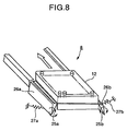
- the rack separating mechanism 8 has a pair of hook bars 26a and 26b separated so as to leave a space therebetween the size of which matches the width of the part rack.
- the transversally long hook bars 26a and 26b are attached to rotating shafts 25a and 25b in such a manner that their transversally long directions are parallel.
- the transversally long hook bars 26a and 26b are formed of relatively thin metal (for example, stainless steel) and are thus somewhat elastic.
- the hook bars 26a and 26b have shell parts 68a and 68b, respectively, formed in the vertical middle thereof and on which the protruding parts 65a and 65b of the part rack 12 can be laid.
- the hook bars 26a and 26b have their sides pressed by torsion springs 27a and 27b, respectively, attached to the rotating shafts 25a and 25b, respectively.
- the springs 27a and 27b may pull the lower ends of the hook bars 26a and 26b, respectively, as shown in FIG. 8.
- the essential point is that the shelf parts 68a and 68b of the hook bars normally undergo such rotational force that the shelf parts are closed in the direction (inward) in which they approach each other.
- the hook bars 26a and 26b have their upper ends abutted against stoppers 61a and 61b, respectively, which restricts rotation of the hook bars so as to prevent them from being closed beyond their predetermined positions. While the hook bars 26a and 26b are abutting against the stoppers 61a and 61b, respectively (normal state), the distance between the pair of shelf parts 68a and 68b is smaller than that between the tips of the pair of protruding parts 65a and 65b of the part rack 12 and larger than the width of the part rack 12 excluding the protruding parts 65a and 65b.
- the rack separation station A can receive a part rack when it has no part racks.
- the upper ends of the hook bars 26a and 26b abut against the stoppers 61a and 61b, respectively.
- a plurality of part racks 12 holding unused disposable parts 13a and 13b are raised by the feeding lift 83 while being stacked together.
- the protruding parts 65a and 65b abutted against the sides of the hook bars 26a and 26b, respectively, push open the hook bars 26a and 26b, respectively, as the part rack is raised.
- the protruding parts 65a and 65b of the part rack 12a pass by the shelf parts 68a and 68b of the hook bars 26a and 26b, respectively, thereby narrowing the hook bars 26a and 26b due to the spring force. Consequently, the interval between the shelf parts 68a and 68b becomes smaller than the interval between the protruding parts 65a and 65b.
- the uppermost position sensor 7 senses the uppermost part rack 12a and transmits a sensor signal to the controller 90.
- the controller 90 controls the supply lifter 14 to stop lifting.
- the protruding parts of the second part rack 12b from the top are kept in the state present before they come into contact with the hook bars 26a and 26b. Accordingly, the hook bars 26a and 26b remain closed.
- the feeding lift 83 starts a lowering operation.
- the shelf parts 68a and 68b of the hook bars 26a and 26b acts as a pair of hindering members for hindering the part rack 12a, located at the uppermost position during the ascent, from lowering. That is, the part racks 12b, 12c, ..., located at the second and subsequent positions during the ascent, lower due to their weights in such a manner as to follow the lowering operation of the lift 83.
- the part rack 12a located at the uppermost position during the ascent, is not lowered because the shelf parts 68a and 68b of the hook bard 26a and 26b are narrowed to keep the protruding parts 65a and 65b sitting on the shelf parts 68a and 68b. This allows the uppermost part rack to be separated from the other part racks.
- the second position sensor 28 arranged in the vicinity of the hook bars 26a and 26b for monitoring a position slightly lower than the lower end of the uppermost part rack 12a, determines whether or not the part rack 12a, located at the uppermost position during the ascent, is present. If the rack separation has been normally executed, the second position sensor does not sense the part rack. However, if the uppermost part rack 12a has lowered with the other part racks rather than being held by the rack separating mechanism 8, the second position sensor senses its presence. On the basis of sensor signals from the uppermost position sensor 7 and the second position sensor 28, the controller 90 judges whether or not the uppermost part rack 12a has been normally separated from the other part racks.
- the lift 83 lowers to the lowest position (bottom dead center).
- the part feeding device 80 continues to perform subsequent operations.
- the controller 90 stops the part feeding device 80 from performing subsequent operations, and causes a buzzer 45 such as the one shown in FIG. 2 to produce a warning sound and/or causes a display 44 such as a CRT to provide alarm information, thereby warning the operator.
- the controller 90 receives a signal from the position sensor 24 for detecting the lowest position, counts the number of pulses transmitted to the pulse motor 20 'in order to lower the lift 83 from the highest position to the lowest position, calculates the number of part racks 12 remaining on the feeding lift 83 on the basis of the number of pulses, and shows, on the display 44, the number of remaining part racks and the number of part racks that can be added to the lift 83. In this case, at the same time, the number of disposable parts remaining on the lift 83 may be calculated and shown on the display 44.
- the controller 90 uses the buzzer 45 and the display 44 to warn the operator to urge him or her to add unused part racks to the lift 83. If both the lifts 83 and 84 are at the lowest positions, even when the part take-out station B is taking out parts, new part racks can be added to the feeding lift 83, while used part racks can be removed from the recovering lift 84.
- the part rack 12a separated from the other part racks 12b and 12c on the rack separation station A, is moved from the rack separation station A to the rack take-out station B by the rack feeding mechanism 95, shown in FIG. 2.
- the configuration of the rack feeding mechanism 95 will be described with reference to FIGS. 2 and 12.
- the rack feeding mechanism 95 comprises the timing belt 5 installed so as to be rotationally moved between the rotating shaft of the pulse motor 4 and the pulley 10.
- the timing belt 5 has a shift lever 9 attached thereto.
- a driving operation performed by the pulse motor 4 causes the shift lever 9 to reciprocate between a standby position (see FIG. 12) located at the leading position of the rack separation station A and a position at which it is pushed out to the part take-out station (see FIG. 2).
- the part rack separated from the other part racks on the rack separation station A is positioned on the part take-out station B by causing the shift lever 9 to push the rear side of this part rack.
- the shift lever 9, which has pushed out the part rack 12a in the horizontal direction returns to the original standby position before the new part rack 12b is fed to the rack separation station A. At this position, the shift lever 9 stands by so that the next part rack can be fed.
- a position sensor 43 senses that the shift lever 9 has reached the proper push-out position
- a position sensor 47 senses that the shift lever 9 has returned to the original standby position.
- the part rack 12a which has reached the part take-out station B, is positioned by bearings 30a, 30b, and 30c as part rack pressing members of the rack positioning mechanism 75 so as to be properly fixed in all of the longitudinal, transversal, and vertical directions.
- the rack positioning mechanism 75 arranged correspondingly to the part take-out station B, comprises two arms 29a and 29b formed of metal plates and arranged opposite each other.
- the larger arm 29a has the bearings 30b and 30c abutted against the part rack 12a and attached to the arm 29a at such an angle (for example, 45° relative to the horizontal) that pressure is exerted on the part rack 12a in both the vertical and horizontal directions.
- the smaller arm 29b has the bearing 30a similarly attached thereto at such an angle (for example, 45°) that pressure is exerted on the part rack 12a in both the vertical and horizontal directions.
- bearings are located correspondingly to a plurality of positioning recesses 46a, 46b, and 46c formed on parallel and opposite upper edges of the part rack 12 as shown in FIG. 14.
- the part rack 12a When the part rack 12a is fixed in position, it is abutted so that each bearing is fitted in the corresponding recess.
- the rack positioning mechanism 75 is operated in connection with the floor-part opening and closing mechanism 11 (FIG. 13).
- the floor part of the part take-out station B, on which part racks are placed is composed of a pair of movable plates 34a and 34b that can be opened and closed in the horizontal direction. These movable plates constitute part of the floor-part opening and closing mechanism 11.
- the arm 29a of the rack positioning mechanism 75 is attached to the movable plate 34a, and the other arm 29b is attached to the movable plate 34b.
- the movable plate 34a is fixed to a slider 77a
- the other movable plate 34b is fixed to a slider 77b.
- the arms 29a and 29b in FIG. 13 have shapes slightly different from those shown in FIG. 12, but have the same functions as the arms in FIG. 12.
- the sliders 77a and 77b can slide along a slide shaft 76. As the sliders slide, the pair of movable plates 34a and 34b change the interval therebetween while remaining parallel with each other, and function as a floor part when positioning a rack part or as a floor-part opening and closing member when recovering a part rack.
- the floor-part opening and closing mechanism 11 has a timing belt 31 extended between a pulley 32b attached to a rotating shaft of a pulse motor 33 and a pulley 32a located horizontally relative to the pulley 32b.
- the sliders 77a and 77b are set on the timing belt 31 so that as the timing belt 31, driven by the pulse motor, moves, the two sliders 77a and 77b approach or leave each other.
- the floor-part opening and closing mechanism 11 opens and closes the movable plates 34a and 34b through three stages.
- the first stage corresponds to an open and close state of the movable plates 34a and 34b maintained when the part rack 12 is moved from the rack separation station A to the part take-out station B.
- the arms 29a and 29b are half-opened so that the bearings 30a and 30b as rack pressing members will not contact with the transferred part rack 12.
- the interval between the two plates 34a and 34b is in an intermediate state in which the plates 34a and 34b can support the upper end (bottom) of the transferred part rack 12 so that the rack 12 will not fall.
- the movable plates 34a and 34b stand by while remaining open in the intermediate state, which corresponds to the first stage.
- the second stage corresponds to an open and close state of the movable plates 34a and 34b maintained when the part rack 12 that has reached the part take-out station B is precisely positioned so as to be correctly taken out by the movable holding part 59 of the part transporting device 70.
- the interval between the pair of movable plates 34a and 34b is kept smallest among the three stages.
- the second stage is carried out after the first stage; the interval between the movable plates 34a and 34b is reduced so as to press the plurality of bearings 30a, 30b, and 30c against the part rack 12 on the movable plates 34a and 34b.
- the interval between the pair of arms 29a and 29b is reduced to abut and fix the three bearings against and to the three corresponding recesses 46a, 46b, and 46c in the part rack 12, sandwiched between the arms 29a and 29b, thereby precisely positioning the part rack on the part take-out station B in all of the longitudinal, transversal, and vertical directions.
- the pressing members 30a, 30b, and 30c may each have a cylindrical shape as shown in the figure, or a spherical shape or another similar shape.
- the pressing members (bearings) are fitted in the corresponding recesses 46a, 46b, and 46c to correct the horizontal position of the part rack. Further, since the direction of the pressing force of the pressing members inclines relative to a horizontal and vertical surfaces, partial force that presses the part rack 12 downward is generated to prevent the rack 12 from floating.
- the third stage corresponds to an open and close state of the movable plates 34a and 34b maintained when the empty part rack 12 from which the parts 13 have been consumed is recovered from the part take-out station B and transferred to the lift 84 of the rack recovering part.
- the maximum interval is maintained between the pair of movable plates 34a and 34b. This maximum interval is larger than the distance between the opposite ends of the protruding parts 65a and 65b, so that the empty part rack 12 falls onto the lift 84 so as to stack up on already recovered empty racks, the lift 84 having been raised up to a position closer to the part take-out station B than to the lowest position.
- the rack recovering part to recover used part racks will be described with reference to FIGS. 3, 4, and 5.
- the parts are consumed one by one, and when few parts remain on the part rack 12, the lift 84, which has been standing by at the lowest position, is raised to the part take-out station B.
- the controller 90 stops raising the lift 84. In this case, even if no recovered empty racks are placed on the lift, the uppermost position sensor 40 senses the receiving member 19b, which is substantially as high as the part rack on the lift 84, to similarly stop the lift.
- the controller 90 controls the operation of the pulse motor 33 of the floor-part opening and closing mechanism 11 to maximize the opening of the pair of movable plates 34b and 34b to drop the used part rack 12 onto the lift 84. That passage through which the part rack falls is limited by the guide wall 35 to fit the outward form of the part rack, so that the part rack falls a short distance while maintaining substantially the same position as that it assumed on the part take-out station, and then sits on the already recovered other part racks or the receiving member 19b.
- the part rack falls from the part take-out station B to the uppermost position sensor 40. This short falling distance serves to make possible noise low during the fall and to prevent the part rack from being damaged. Further, the part rack can be reliably staked up on the other part racks while maintaining its position.
- the controller 90 When the fall detecting sensor 16, arranged in the fall passage, senses that the part rack 12 has fallen, the controller 90 realizes that the part rack has been normally recovered, and lowers the lift 84 down to the lowest position. When the fall detecting sensor 16 does not sense the part rack, the controller 90 lowers the lift 84 down to the lowest position, while determining that an error has occurred during the receiving operation to output a warning notifying the operator of the error, using the buzzer 45 and/or display 44.
- the controller 90 calculates the number of part racks recovered and placed on the lift 84.
- the controller 90 outputs a warning using the buzzer 44 and/or display 44 to urge the operator to take out the recovered part racks from the rack recovering part.
- This configuration enables up to a predetermined number of the used part racks to be recovered in order while being stacked together on the lift, thereby reducing the required volume of the recovering part.
- the supply lifter 14 is arranged by the side of the recovery lifter 15 to feed unused part racks with unused disposable parts mounted thereon, thereby reducing the required floor area of the part feeding device 80.
Abstract
Description
Then, when the
Claims (16)
- An automatic analyzer that analyzes samples using disposable parts used in contact with the samples and changed for each sample, characterized by comprising:a lift that raises a plurality of part racks holding unused disposable parts to a rack separation station, while keeping the part racks stacked together;a rack separator that hinders the uppermost one of said stacked part racks from being lowered when said lift lowers, while allowing the other part racks to lower, so that said uppermost rack is separated from said other part racks so as to remain in said rack separation station; anda rack recovering part that operates after the parts on the separated part rack have been consumed, to move this used part rack downward for recovery.
- The automatic analyzer according to Claim 1, characterized in that said part rack holds a plurality of disposable nozzle tips and disposable reaction containers.
- The automatic analyzer according to Claim 1, characterized in that said part rack is shaped like a trapezoid having a lower edge larger than an upper edge, and said part rack has protruding parts formed on at least two opposed side walls and which can abut against fall hindering members of said rack separator.
- The automatic analyzer according to Claim 1, characterized in that said lift is housed in a rack lift chamber having a part introducing door locked while said lift is in operation.
- The automatic analyzer according to Claim 1, characterized in that said rack separator has a pair of hindering members that hinder the uppermost part rack from lowering, and the pair of hindering members operate so that their interval increases when said uppermost part rack is raised to said rack separation station and decreases after said uppermost part rack has passed by the position of the pair of hindering members and before the second part rack from the top passes by the position of said pair of hindering members.
- The automatic analyzer according to Claim 1, characterized in that said lift comprises a lift having a rack receiver formed thereon and which can move into said part rack.
- The automatic analyzer according to Claim 1, characterized in that a first rack position sensor that senses the uppermost one of the stacked part racks and a second rack position sensor that senses the second part rack from the top of the stacked part racks are arranged in the vicinity of said rack separation station, and the analyzer comprises a control part that determines whether or not said uppermost part rack has been properly separated from the other part racks on the basis of sensed information from said first and second rack position sensor.
- An automatic analyzer that analyzes samples using disposable parts used in contact with the samples and changed for each sample, characterized by comprising:a lift that raises a plurality of part racks holding unused disposable parts to a rack separation station, while keeping the part racks stacked together;a rack separator that holds the uppermost one of the stacked part racks so as to leave it on said rack separation station;a rack positioning device that presses the part rack taken out from said rack separation station and then moved to a part take-out station, at a plurality of points thereof so that the part rack rests at a predetermined position; anda part take-out device that takes out disposable parts from the said positioned part rack.
- The automatic analyzer according to Claim 8, characterized in that said part rack has positioning recesses formed at a pair of opposite upper edges thereof, and said rack positioning device comprises members that abut against said positioning recesses.
- A part feeding device, characterized by comprising:a supply lifter having a lift that can move a plurality of part racks while keeping them stacked together, the part racks each holding a plurality of disposable parts used to handle samples, the lift being raised to a rack separation station when the rack separation station can receive a new part rack;a rack separator that takes out the uppermost one of the stacked part racks from said rack separation station so as to separate the uppermost part rack from the other part racks;a rack feeding device that moves the separated part rack in a horizontal direction from said rack separation station to a part take-out station; anda recovery lifter having a lift that receives the part rack from which the parts have been consumed while the part rack is on said part take-out station, at a position higher than the lowest position after part consumption.
- The part feeding device according to Claim 10, characterized in that the lift of said recovery lifter has a rack receiver that can move into the part rack from which the parts have been consumed, in order to receive the part rack.
- The part feeding device according to Claim 11, characterized in that after receiving the part rack from which the parts have been consumed, at the position higher than said lowest position after part consumption, the lift of said recovery lifter lowers down to said lowest position.
- The part feeding device according to Claim 10, characterized in that the lift of said recovery lifter is raised and lowered through a space limited by a guide wall arranged to fit the size of said part rack.
- The part feeding device according to Claim 10, characterized in that said part take-out station is arranged on an extension of a direction in which the lift of said recovery lifter is raised, and the part rack on said part take-out station is placed on an openable and closable member that is opened when the lift of said recovery lifter receives the part rack.
- An automatic analyzer that analyzes samples by taking out a disposable nozzle tip from a part rack located on a part take-out station and pipetting a sample from a sample container in the taken-put nozzle tip to a reaction container, characterized by comprising:a lift that raises a lift on which a plurality of part racks holding unused disposable nozzle tips are stacked together;a sensor that senses that the uppermost one of the plurality of part racks raised by said lift has reached a rack separation station;a rack separating device that holds and hinders said uppermost part rack from falling from said rack separation station on the basis of the sensing of said uppermost part rack by the sensor; anda rack transferring device that transfers, by lowering said lift, said uppermost part rack separated from the other part racks, from said rack separation station to said part take-out station.
- The automatic analyzer according to Claim 15, characterized by further comprising a transporting device that takes out a disposable part from the part rack on said part take-out station and transports this part to a predetermined position, and in that each part rack holding said nozzle tips also holds disposable reaction containers, and said transporting device that performs an operation of transporting a nozzle tip on said part rack to a position at which an unused nozzle tip is installed in a sampling device and an operation of transporting a reaction container on said part rack to a reaction part in which a sample and a reagent are allowed to react with each other.
Priority Applications (1)
| Application Number | Priority Date | Filing Date | Title |
|---|---|---|---|
| AT00909648T ATE333098T1 (en) | 2000-03-15 | 2000-03-15 | AUTOMATIC ANALYZER AND PARTS FEEDING DEVICE USED FOR IT |
Applications Claiming Priority (1)
| Application Number | Priority Date | Filing Date | Title |
|---|---|---|---|
| PCT/JP2000/001574 WO2001069263A1 (en) | 2000-03-15 | 2000-03-15 | Automatic analyzer and part feeding device used for the analyzer |
Publications (3)
| Publication Number | Publication Date |
|---|---|
| EP1275966A1 true EP1275966A1 (en) | 2003-01-15 |
| EP1275966A4 EP1275966A4 (en) | 2003-04-23 |
| EP1275966B1 EP1275966B1 (en) | 2006-07-12 |
Family
ID=11735796
Family Applications (1)
| Application Number | Title | Priority Date | Filing Date |
|---|---|---|---|
| EP00909648A Expired - Lifetime EP1275966B1 (en) | 2000-03-15 | 2000-03-15 | Automatic analyzer and part feeding device used for the analyzer |
Country Status (6)
| Country | Link |
|---|---|
| US (1) | US7360984B1 (en) |
| EP (1) | EP1275966B1 (en) |
| JP (1) | JP4454904B2 (en) |
| DE (1) | DE60029356T2 (en) |
| ES (1) | ES2262511T3 (en) |
| WO (1) | WO2001069263A1 (en) |
Cited By (12)
| Publication number | Priority date | Publication date | Assignee | Title |
|---|---|---|---|---|
| WO2005085874A1 (en) * | 2004-03-05 | 2005-09-15 | Matsushita Electric Industrial Co., Ltd. | Apparatus of supplying and containing micro-plate, method of supplying and method of containing micro-plate and apparatus of processing micro-plate |
| US7105129B2 (en) | 2002-05-15 | 2006-09-12 | Genetix Limited | Liquid handling robot for well plates |
| EP1941948A1 (en) * | 2006-12-13 | 2008-07-09 | Hamilton Bonaduz AG | Device for receiving pipette tips |
| EP2515120A1 (en) | 2011-04-19 | 2012-10-24 | F. Hoffmann-La Roche AG | Supply unit for continuous loading |
| CN104020309A (en) * | 2014-06-25 | 2014-09-03 | 长春迪瑞医疗科技股份有限公司 | Automatic consumable tray loading device of full-automatic chemiluminescence immunoassay analyzer |
| CN104108603A (en) * | 2013-04-16 | 2014-10-22 | 深圳迈瑞生物医疗电子股份有限公司 | Cup box grabbing mechanism and cup box grabbing method |
| CN104111340A (en) * | 2013-04-16 | 2014-10-22 | 深圳迈瑞生物医疗电子股份有限公司 | Cup-shaped box automatic conveying device, immunity analyzer, and cup-shaped box automatic conveying method |
| IT201600130628A1 (en) * | 2016-12-23 | 2018-06-23 | Inpeco Holding Ltd | Liquid handling equipment |
| WO2020002518A1 (en) | 2018-06-29 | 2020-01-02 | Roche Diagnostics Gmbh | Automatic analyzer |
| EP3588096A4 (en) * | 2017-02-22 | 2021-01-06 | Hitachi High-Tech Corporation | Automated analyzer |
| EP4187251A1 (en) * | 2017-09-13 | 2023-05-31 | Hitachi High-Tech Corporation | Automated analyzing device |
| EP3109642B1 (en) * | 2015-06-25 | 2024-04-10 | Roche Diagnostics GmbH | Device and method for handling racks of disposable pipette tips in a laboratory automation system and laboratory automation system |
Families Citing this family (51)
| Publication number | Priority date | Publication date | Assignee | Title |
|---|---|---|---|---|
| JP3802266B2 (en) * | 1999-03-25 | 2006-07-26 | 独立行政法人科学技術振興機構 | AFM cantilever made of functional organic polymer gel |
| JP3778002B2 (en) * | 2001-05-10 | 2006-05-24 | 松下電器産業株式会社 | Dispensing device |
| JP3675746B2 (en) * | 2001-09-11 | 2005-07-27 | アロカ株式会社 | Sample pretreatment equipment |
| JP3873982B2 (en) * | 2004-03-05 | 2007-01-31 | 松下電器産業株式会社 | Microplate feeding device with lid |
| JP3873983B2 (en) * | 2004-03-05 | 2007-01-31 | 松下電器産業株式会社 | Microplate feeder |
| US7914737B2 (en) * | 2004-07-01 | 2011-03-29 | Roche Molecular Systems, Inc. | Multi-level diagnostic apparatus with a lift system |
| WO2010053398A1 (en) * | 2008-11-07 | 2010-05-14 | Izvozchikov Ilya Borisovitch | Device for placing slides into trays |
| JP5152678B2 (en) * | 2009-03-12 | 2013-02-27 | 横河電機株式会社 | Dispensing device |
| EP2429710B1 (en) * | 2009-05-15 | 2020-08-19 | Gen-Probe Incorporated | Method and system for performing a magnetic separation procedure |
| CA2769501C (en) | 2009-07-29 | 2015-07-07 | F. Hoffmann-La Roche Ag | Automatic analyzer |
| JP5662124B2 (en) * | 2009-12-10 | 2015-01-28 | エフ.ホフマン−ラ ロシュ アーゲーF. Hoffmann−La Roche Aktiengesellschaft | Hardware coding system for consumables |
| US20110300621A1 (en) * | 2009-12-10 | 2011-12-08 | Roche Molecular Systems, Inc. | Process head positioning |
| US9744535B2 (en) * | 2010-04-19 | 2017-08-29 | Roche Molecular Systems, Inc. | Cassette with multiwell plates |
| CN102249094B (en) * | 2010-05-18 | 2013-05-08 | 鸿富锦精密工业(深圳)有限公司 | Feeding device |
| CN102408011B (en) * | 2010-09-24 | 2013-08-28 | 鸿富锦精密工业(深圳)有限公司 | Feeding device |
| JP5808634B2 (en) * | 2011-09-30 | 2015-11-10 | シスメックス株式会社 | Sample processing equipment |
| CN102621341B (en) * | 2012-03-16 | 2013-07-17 | 北京勤邦生物技术有限公司 | Reaction cup storage device |
| JP5492935B2 (en) * | 2012-05-15 | 2014-05-14 | あおい精機株式会社 | Rack storage device |
| CN103523538B (en) * | 2012-07-06 | 2016-02-03 | 鸿富锦精密工业(深圳)有限公司 | Pay-off |
| EP2703820B1 (en) | 2012-08-31 | 2019-08-28 | F. Hoffmann-La Roche AG | Mobile tip waste rack |
| JP6009881B2 (en) * | 2012-09-20 | 2016-10-19 | シスメックス株式会社 | Specimen transfer device and specimen processing system |
| CA2791003C (en) * | 2012-09-27 | 2013-08-06 | Cinrg Systems Inc. | Liquid sample testing apparatus |
| JP2014077757A (en) * | 2012-10-12 | 2014-05-01 | Tosoh Corp | Supply device for disposable component |
| ES2747428T3 (en) * | 2012-11-12 | 2020-03-10 | Siemens Healthcare Diagnostics Products Gmbh | Reagent station for an automatic analysis apparatus |
| JP2014119297A (en) * | 2012-12-14 | 2014-06-30 | Tosoh Corp | Feeding device of nozzle tip and automatic analyzer having the same |
| JP2014126392A (en) * | 2012-12-25 | 2014-07-07 | Tosoh Corp | Feeder of nozzle chip rack |
| CN103983797B (en) * | 2013-01-31 | 2018-05-04 | 希森美康株式会社 | Classfication of containers device, sample processing system and Classfication of containers method |
| JP5887497B2 (en) * | 2013-02-26 | 2016-03-16 | パナソニックIpマネジメント株式会社 | Parts supply device |
| CN105745546B (en) | 2013-03-15 | 2017-10-13 | 雅培制药有限公司 | With below can injection system automated diagnostic analyzer and correlation technique |
| CN116794337A (en) | 2013-03-15 | 2023-09-22 | 雅培制药有限公司 | Automated diagnostic analyzer with vertically disposed carousel and related methods |
| CN108196079B (en) | 2013-03-15 | 2021-10-08 | 雅培制药有限公司 | Diagnostic analyzer with pre-processing carousel and related methods |
| CN103336138B (en) * | 2013-06-13 | 2015-04-08 | 长春迪瑞医疗科技股份有限公司 | Automatic loading device for full-automatic chemiluminescence immunoassay analyzer |
| CN104422779B (en) * | 2013-08-22 | 2016-03-09 | 钟伟明 | Automatic lmunoassays analyzer |
| JP6427389B2 (en) * | 2013-11-06 | 2018-11-21 | 協和メデックス株式会社 | Rack storage device and analysis device |
| EP3006110A1 (en) | 2014-10-10 | 2016-04-13 | F.Hoffmann-La Roche Ag | Rack |
| JP6500233B2 (en) * | 2015-10-27 | 2019-04-17 | パナソニックIpマネジメント株式会社 | Tray supply apparatus and tray supply method |
| CN105388314B (en) * | 2015-12-17 | 2017-09-12 | 嘉兴凯实生物科技有限公司 | A kind of full-automatic sample adding instrument |
| WO2017163607A1 (en) * | 2016-03-23 | 2017-09-28 | 株式会社 日立ハイテクノロジーズ | Automatic analysis device |
| CN105880964B (en) * | 2016-04-25 | 2017-12-26 | 谢秀英 | 3rd hold-down hook feed mechanism of automobile exhaust pipe kludge |
| EP3450985B1 (en) | 2017-08-31 | 2023-07-12 | Tecan Trading Ag | Microplate processing device |
| EP3454064B1 (en) * | 2017-09-08 | 2020-11-11 | F. Hoffmann-La Roche AG | Rack positioning system |
| WO2019082436A1 (en) * | 2017-10-23 | 2019-05-02 | 株式会社島津製作所 | Sample plate and auto-sampler |
| JP6946150B2 (en) * | 2017-11-08 | 2021-10-06 | 株式会社日立ハイテク | Automatic analyzer |
| CN109765217B (en) * | 2017-11-09 | 2023-05-30 | 深圳市新产业生物医学工程股份有限公司 | Chemiluminescence detector, consumable box automatic transmission device and transmission method thereof |
| JP7100877B2 (en) | 2017-11-17 | 2022-07-14 | 株式会社テクノメデイカ | Blood collection tray transfer system |
| EP3578485B1 (en) | 2018-06-08 | 2021-08-18 | F. Hoffmann-La Roche AG | Vessel dispensing system |
| CN110007101A (en) * | 2019-04-09 | 2019-07-12 | 安邦(厦门)生物科技有限公司 | Detection device and detection method |
| CN113994213A (en) * | 2019-06-24 | 2022-01-28 | 积水医疗株式会社 | Automatic analyzer |
| CN110510311A (en) * | 2019-08-23 | 2019-11-29 | 中南大学湘雅医院 | A kind of Riker mount distribution recyclable device |
| CN111551417B (en) * | 2020-04-01 | 2023-08-11 | 郑州中普医疗器械有限公司 | Automatic film-making device |
| JP7022855B2 (en) * | 2021-03-05 | 2022-02-18 | 株式会社日立ハイテク | Automated analyzer, consumables supply device and consumables supply method |
Citations (3)
| Publication number | Priority date | Publication date | Assignee | Title |
|---|---|---|---|---|
| US5009316A (en) * | 1988-03-29 | 1991-04-23 | Klein David C | Test tube cassette system and cassettes for use therein |
| EP0654668A1 (en) * | 1993-11-22 | 1995-05-24 | Fuji Photo Film Co., Ltd. | Chemical analysis element cartridge |
| EP0937983A1 (en) * | 1992-04-09 | 1999-08-25 | F. Hoffmann-La Roche Ag | Automatic analyser |
Family Cites Families (13)
| Publication number | Priority date | Publication date | Assignee | Title |
|---|---|---|---|---|
| US4724215A (en) * | 1985-02-27 | 1988-02-09 | Sherwood Medical Company | Automated microbiological testing apparatus and method |
| US5190434A (en) * | 1989-03-14 | 1993-03-02 | Canon Kabushiki Kaisha | Article supplier |
| JPH032287U (en) | 1989-05-26 | 1991-01-10 | ||
| US5827745A (en) * | 1993-03-29 | 1998-10-27 | Astle; Thomas W. | Micropipette tip loading and unloading device and method and tip package |
| US5392914A (en) * | 1993-09-21 | 1995-02-28 | Rainin Instrument Co., Inc. | Refill pack for pipette tip racks |
| US5639425A (en) * | 1994-09-21 | 1997-06-17 | Hitachi, Ltd. | Analyzing apparatus having pipetting device |
| JPH0894637A (en) | 1994-09-21 | 1996-04-12 | Fuji Photo Film Co Ltd | Biochemistry analysis device |
| JP3267117B2 (en) | 1994-09-21 | 2002-03-18 | 株式会社日立製作所 | Analyzer with dispensing device |
| US5674047A (en) * | 1995-07-13 | 1997-10-07 | Chiron Diagnostics Corporation | Loading mechanism for probe tip tray |
| KR100310249B1 (en) * | 1995-08-05 | 2001-12-17 | 엔도 마코토 | Substrate Processing Equipment |
| CA2192893C (en) * | 1995-12-15 | 2001-02-20 | Klaus D. Woerner | System for loading or unloading of parts onto or from trays |
| JP3489430B2 (en) | 1998-03-26 | 2004-01-19 | 松下電器産業株式会社 | Automatic dispensing device and dispensing method |
| JP3584732B2 (en) * | 1998-05-08 | 2004-11-04 | 松下電器産業株式会社 | Dispensing device, dispensing method and dispensing tip mounting method |
-
2000
- 2000-03-15 JP JP2001568091A patent/JP4454904B2/en not_active Expired - Fee Related
- 2000-03-15 EP EP00909648A patent/EP1275966B1/en not_active Expired - Lifetime
- 2000-03-15 DE DE60029356T patent/DE60029356T2/en not_active Expired - Lifetime
- 2000-03-15 WO PCT/JP2000/001574 patent/WO2001069263A1/en active IP Right Grant
- 2000-03-15 US US10/069,580 patent/US7360984B1/en not_active Expired - Fee Related
- 2000-03-15 ES ES00909648T patent/ES2262511T3/en not_active Expired - Lifetime
Patent Citations (3)
| Publication number | Priority date | Publication date | Assignee | Title |
|---|---|---|---|---|
| US5009316A (en) * | 1988-03-29 | 1991-04-23 | Klein David C | Test tube cassette system and cassettes for use therein |
| EP0937983A1 (en) * | 1992-04-09 | 1999-08-25 | F. Hoffmann-La Roche Ag | Automatic analyser |
| EP0654668A1 (en) * | 1993-11-22 | 1995-05-24 | Fuji Photo Film Co., Ltd. | Chemical analysis element cartridge |
Non-Patent Citations (1)
| Title |
|---|
| See also references of WO0169263A1 * |
Cited By (17)
| Publication number | Priority date | Publication date | Assignee | Title |
|---|---|---|---|---|
| US7105129B2 (en) | 2002-05-15 | 2006-09-12 | Genetix Limited | Liquid handling robot for well plates |
| US7628960B2 (en) | 2002-05-15 | 2009-12-08 | Genetix Limited | Liquid handling robot for well plates |
| WO2005085874A1 (en) * | 2004-03-05 | 2005-09-15 | Matsushita Electric Industrial Co., Ltd. | Apparatus of supplying and containing micro-plate, method of supplying and method of containing micro-plate and apparatus of processing micro-plate |
| EP1941948A1 (en) * | 2006-12-13 | 2008-07-09 | Hamilton Bonaduz AG | Device for receiving pipette tips |
| US9164114B2 (en) | 2011-04-19 | 2015-10-20 | Roche Molecular Systems, Inc. | Supply unit for continuous loading |
| EP2515120A1 (en) | 2011-04-19 | 2012-10-24 | F. Hoffmann-La Roche AG | Supply unit for continuous loading |
| CN104108603A (en) * | 2013-04-16 | 2014-10-22 | 深圳迈瑞生物医疗电子股份有限公司 | Cup box grabbing mechanism and cup box grabbing method |
| CN104111340A (en) * | 2013-04-16 | 2014-10-22 | 深圳迈瑞生物医疗电子股份有限公司 | Cup-shaped box automatic conveying device, immunity analyzer, and cup-shaped box automatic conveying method |
| CN104111340B (en) * | 2013-04-16 | 2016-02-03 | 深圳迈瑞生物医疗电子股份有限公司 | A kind of cup box automatic conveying device, immunity analysis instrument and cup box automatic transport method |
| CN104020309A (en) * | 2014-06-25 | 2014-09-03 | 长春迪瑞医疗科技股份有限公司 | Automatic consumable tray loading device of full-automatic chemiluminescence immunoassay analyzer |
| EP3109642B1 (en) * | 2015-06-25 | 2024-04-10 | Roche Diagnostics GmbH | Device and method for handling racks of disposable pipette tips in a laboratory automation system and laboratory automation system |
| IT201600130628A1 (en) * | 2016-12-23 | 2018-06-23 | Inpeco Holding Ltd | Liquid handling equipment |
| WO2018116261A1 (en) * | 2016-12-23 | 2018-06-28 | Inpeco Holding Ltd. | Liquid handling apparatus |
| CN110168382A (en) * | 2016-12-23 | 2019-08-23 | 英派克控股有限公司 | Liquid treatment equipment |
| EP3588096A4 (en) * | 2017-02-22 | 2021-01-06 | Hitachi High-Tech Corporation | Automated analyzer |
| EP4187251A1 (en) * | 2017-09-13 | 2023-05-31 | Hitachi High-Tech Corporation | Automated analyzing device |
| WO2020002518A1 (en) | 2018-06-29 | 2020-01-02 | Roche Diagnostics Gmbh | Automatic analyzer |
Also Published As
| Publication number | Publication date |
|---|---|
| ES2262511T3 (en) | 2006-12-01 |
| US7360984B1 (en) | 2008-04-22 |
| EP1275966B1 (en) | 2006-07-12 |
| DE60029356D1 (en) | 2006-08-24 |
| DE60029356T2 (en) | 2007-02-15 |
| WO2001069263A1 (en) | 2001-09-20 |
| JP4454904B2 (en) | 2010-04-21 |
| EP1275966A4 (en) | 2003-04-23 |
Similar Documents
| Publication | Publication Date | Title |
|---|---|---|
| EP1275966B1 (en) | Automatic analyzer and part feeding device used for the analyzer | |
| US11754582B2 (en) | Automated diagnostic analyzer and method for its operation | |
| EP2515120B1 (en) | Supply unit for continuous loading | |
| CN108780104B (en) | Automatic analyzer | |
| US9446900B2 (en) | Tube sorter and tube sorting system | |
| US8840851B2 (en) | Pipette tip supplying apparatus, sample analyzer and pipette tip supplying method | |
| CN110140054B (en) | Automatic analyzer | |
| JPH04115160A (en) | Automatic analyzer for specimen | |
| JP7316763B2 (en) | Automated devices for the automated execution of analyses, especially medical analyses. | |
| CN211846220U (en) | Automatic sequencing device | |
| US20210088543A1 (en) | Automatic analyzer | |
| CN216144814U (en) | Immunoassay analyzer | |
| CN219084965U (en) | Inventory handling apparatus in automated diagnostic analyzer | |
| US20240142482A1 (en) | Specimen measurement apparatus and specimen transport device | |
| EP3988939A1 (en) | Automatic analysis device and reagent accommodation unit | |
| EP3988942A1 (en) | Automated analysis device | |
| CN115575655A (en) | Sample tube rack storing and taking method and sample tube rack storing and taking assembly in automatic detection system | |
| CN116443555A (en) | Container transfer method and container transfer device | |
| CN117949679A (en) | Sample measurement device and sample transport device | |
| CN117949680A (en) | Sample measurement device and sample transport device | |
| CN117957448A (en) | Apparatus and method for automating inventory processing in a diagnostic analyzer |
Legal Events
| Date | Code | Title | Description |
|---|---|---|---|
| PUAI | Public reference made under article 153(3) epc to a published international application that has entered the european phase |
Free format text: ORIGINAL CODE: 0009012 |
|
| 17P | Request for examination filed |
Effective date: 20021008 |
|
| AK | Designated contracting states |
Kind code of ref document: A1 Designated state(s): AT BE CH CY DE DK ES FI FR GB GR IE IT LI LU MC NL PT SE |
|
| A4 | Supplementary search report drawn up and despatched |
Effective date: 20030312 |
|
| RIC1 | Information provided on ipc code assigned before grant |
Ipc: 7G 01N 35/04 A Ipc: 7G 01N 35/10 B Ipc: 7B 01L 9/06 B Ipc: 7B 01L 3/02 B |
|
| RAP1 | Party data changed (applicant data changed or rights of an application transferred) |
Owner name: F. HOFFMANN-LA ROCHE AG Owner name: HITACHI, LTD. Owner name: ROCHE DIAGNOSTICS GMBH |
|
| 17Q | First examination report despatched |
Effective date: 20040511 |
|
| GRAP | Despatch of communication of intention to grant a patent |
Free format text: ORIGINAL CODE: EPIDOSNIGR1 |
|
| GRAS | Grant fee paid |
Free format text: ORIGINAL CODE: EPIDOSNIGR3 |
|
| GRAA | (expected) grant |
Free format text: ORIGINAL CODE: 0009210 |
|
| AK | Designated contracting states |
Kind code of ref document: B1 Designated state(s): AT BE CH CY DE DK ES FI FR GB GR IE IT LI LU MC NL PT SE |
|
| PG25 | Lapsed in a contracting state [announced via postgrant information from national office to epo] |
Ref country code: IT Free format text: LAPSE BECAUSE OF FAILURE TO SUBMIT A TRANSLATION OF THE DESCRIPTION OR TO PAY THE FEE WITHIN THE PRESCRIBED TIME-LIMIT;WARNING: LAPSES OF ITALIAN PATENTS WITH EFFECTIVE DATE BEFORE 2007 MAY HAVE OCCURRED AT ANY TIME BEFORE 2007. THE CORRECT EFFECTIVE DATE MAY BE DIFFERENT FROM THE ONE RECORDED. Effective date: 20060712 Ref country code: NL Free format text: LAPSE BECAUSE OF FAILURE TO SUBMIT A TRANSLATION OF THE DESCRIPTION OR TO PAY THE FEE WITHIN THE PRESCRIBED TIME-LIMIT Effective date: 20060712 Ref country code: FI Free format text: LAPSE BECAUSE OF FAILURE TO SUBMIT A TRANSLATION OF THE DESCRIPTION OR TO PAY THE FEE WITHIN THE PRESCRIBED TIME-LIMIT Effective date: 20060712 Ref country code: BE Free format text: LAPSE BECAUSE OF FAILURE TO SUBMIT A TRANSLATION OF THE DESCRIPTION OR TO PAY THE FEE WITHIN THE PRESCRIBED TIME-LIMIT Effective date: 20060712 |
|
| REG | Reference to a national code |
Ref country code: GB Ref legal event code: FG4D |
|
| REG | Reference to a national code |
Ref country code: CH Ref legal event code: EP |
|
| REG | Reference to a national code |
Ref country code: CH Ref legal event code: NV Representative=s name: TROESCH SCHEIDEGGER WERNER AG |
|
| REG | Reference to a national code |
Ref country code: IE Ref legal event code: FG4D |
|
| REF | Corresponds to: |
Ref document number: 60029356 Country of ref document: DE Date of ref document: 20060824 Kind code of ref document: P |
|
| PG25 | Lapsed in a contracting state [announced via postgrant information from national office to epo] |
Ref country code: SE Free format text: LAPSE BECAUSE OF FAILURE TO SUBMIT A TRANSLATION OF THE DESCRIPTION OR TO PAY THE FEE WITHIN THE PRESCRIBED TIME-LIMIT Effective date: 20061012 Ref country code: DK Free format text: LAPSE BECAUSE OF FAILURE TO SUBMIT A TRANSLATION OF THE DESCRIPTION OR TO PAY THE FEE WITHIN THE PRESCRIBED TIME-LIMIT Effective date: 20061012 |
|
| REG | Reference to a national code |
Ref country code: ES Ref legal event code: FG2A Ref document number: 2262511 Country of ref document: ES Kind code of ref document: T3 |
|
| PG25 | Lapsed in a contracting state [announced via postgrant information from national office to epo] |
Ref country code: PT Free format text: LAPSE BECAUSE OF FAILURE TO SUBMIT A TRANSLATION OF THE DESCRIPTION OR TO PAY THE FEE WITHIN THE PRESCRIBED TIME-LIMIT Effective date: 20061212 |
|
| NLV1 | Nl: lapsed or annulled due to failure to fulfill the requirements of art. 29p and 29m of the patents act | ||
| ET | Fr: translation filed | ||
| PLBE | No opposition filed within time limit |
Free format text: ORIGINAL CODE: 0009261 |
|
| STAA | Information on the status of an ep patent application or granted ep patent |
Free format text: STATUS: NO OPPOSITION FILED WITHIN TIME LIMIT |
|
| 26N | No opposition filed |
Effective date: 20070413 |
|
| PG25 | Lapsed in a contracting state [announced via postgrant information from national office to epo] |
Ref country code: MC Free format text: LAPSE BECAUSE OF NON-PAYMENT OF DUE FEES Effective date: 20070331 Ref country code: IE Free format text: LAPSE BECAUSE OF NON-PAYMENT OF DUE FEES Effective date: 20070315 |
|
| PG25 | Lapsed in a contracting state [announced via postgrant information from national office to epo] |
Ref country code: GR Free format text: LAPSE BECAUSE OF FAILURE TO SUBMIT A TRANSLATION OF THE DESCRIPTION OR TO PAY THE FEE WITHIN THE PRESCRIBED TIME-LIMIT Effective date: 20061013 |
|
| PG25 | Lapsed in a contracting state [announced via postgrant information from national office to epo] |
Ref country code: CY Free format text: LAPSE BECAUSE OF FAILURE TO SUBMIT A TRANSLATION OF THE DESCRIPTION OR TO PAY THE FEE WITHIN THE PRESCRIBED TIME-LIMIT Effective date: 20060712 Ref country code: LU Free format text: LAPSE BECAUSE OF NON-PAYMENT OF DUE FEES Effective date: 20070315 |
|
| REG | Reference to a national code |
Ref country code: FR Ref legal event code: PLFP Year of fee payment: 17 |
|
| PGFP | Annual fee paid to national office [announced via postgrant information from national office to epo] |
Ref country code: CH Payment date: 20160212 Year of fee payment: 17 Ref country code: ES Payment date: 20160301 Year of fee payment: 17 |
|
| PGFP | Annual fee paid to national office [announced via postgrant information from national office to epo] |
Ref country code: AT Payment date: 20160225 Year of fee payment: 17 |
|
| PGFP | Annual fee paid to national office [announced via postgrant information from national office to epo] |
Ref country code: IT Payment date: 20160324 Year of fee payment: 17 |
|
| REG | Reference to a national code |
Ref country code: FR Ref legal event code: PLFP Year of fee payment: 18 |
|
| REG | Reference to a national code |
Ref country code: CH Ref legal event code: PL |
|
| REG | Reference to a national code |
Ref country code: AT Ref legal event code: MM01 Ref document number: 333098 Country of ref document: AT Kind code of ref document: T Effective date: 20170315 |
|
| REG | Reference to a national code |
Ref country code: FR Ref legal event code: PLFP Year of fee payment: 19 |
|
| PG25 | Lapsed in a contracting state [announced via postgrant information from national office to epo] |
Ref country code: AT Free format text: LAPSE BECAUSE OF NON-PAYMENT OF DUE FEES Effective date: 20170315 |
|
| PG25 | Lapsed in a contracting state [announced via postgrant information from national office to epo] |
Ref country code: IT Free format text: LAPSE BECAUSE OF NON-PAYMENT OF DUE FEES Effective date: 20170315 Ref country code: LI Free format text: LAPSE BECAUSE OF NON-PAYMENT OF DUE FEES Effective date: 20170331 Ref country code: CH Free format text: LAPSE BECAUSE OF NON-PAYMENT OF DUE FEES Effective date: 20170331 |
|
| REG | Reference to a national code |
Ref country code: ES Ref legal event code: FD2A Effective date: 20180629 |
|
| PG25 | Lapsed in a contracting state [announced via postgrant information from national office to epo] |
Ref country code: ES Free format text: LAPSE BECAUSE OF NON-PAYMENT OF DUE FEES Effective date: 20170316 |
|
| PGFP | Annual fee paid to national office [announced via postgrant information from national office to epo] |
Ref country code: GB Payment date: 20190125 Year of fee payment: 20 Ref country code: FR Payment date: 20190131 Year of fee payment: 20 |
|
| PGFP | Annual fee paid to national office [announced via postgrant information from national office to epo] |
Ref country code: DE Payment date: 20190506 Year of fee payment: 20 |
|
| REG | Reference to a national code |
Ref country code: DE Ref legal event code: R071 Ref document number: 60029356 Country of ref document: DE |
|
| REG | Reference to a national code |
Ref country code: GB Ref legal event code: PE20 Expiry date: 20200314 |
|
| PG25 | Lapsed in a contracting state [announced via postgrant information from national office to epo] |
Ref country code: GB Free format text: LAPSE BECAUSE OF EXPIRATION OF PROTECTION Effective date: 20200314 |