EP1275943B1 - Dispositif mobile pour peser une charge - Google Patents
Dispositif mobile pour peser une charge Download PDFInfo
- Publication number
- EP1275943B1 EP1275943B1 EP02447132A EP02447132A EP1275943B1 EP 1275943 B1 EP1275943 B1 EP 1275943B1 EP 02447132 A EP02447132 A EP 02447132A EP 02447132 A EP02447132 A EP 02447132A EP 1275943 B1 EP1275943 B1 EP 1275943B1
- Authority
- EP
- European Patent Office
- Prior art keywords
- load cell
- weighing
- load
- supporting structure
- base plate
- Prior art date
- Legal status (The legal status is an assumption and is not a legal conclusion. Google has not performed a legal analysis and makes no representation as to the accuracy of the status listed.)
- Expired - Lifetime
Links
Images


Classifications
-
- G—PHYSICS
- G01—MEASURING; TESTING
- G01G—WEIGHING
- G01G19/00—Weighing apparatus or methods adapted for special purposes not provided for in the preceding groups
- G01G19/08—Weighing apparatus or methods adapted for special purposes not provided for in the preceding groups for incorporation in vehicles
- G01G19/12—Weighing apparatus or methods adapted for special purposes not provided for in the preceding groups for incorporation in vehicles having electrical weight-sensitive devices
-
- G—PHYSICS
- G01—MEASURING; TESTING
- G01G—WEIGHING
- G01G21/00—Details of weighing apparatus
- G01G21/23—Support or suspension of weighing platforms
Definitions
- the present invention is related to installations for weighing loads.
- the invention is related to a device comprising a supporting structure or base frame and a weighing structure connected to said frame through a number of load cells.
- a prime application of this kind of structures is their use in mobile weighing systems.
- a supporting structure which we will also call a ⁇ frame' or 'base frame' in this text, fixed to the ground or to a truck, is present.
- a weighing structure for example a rectangular platform is suspended from this frame, or is resting on the frame wherein the load exerted by the weighing structure (and the weight placed on it) on the frame is measured by load cells, which are subjected to the forces applied by the weight.
- the present invention is in particular related to load cells which are of the 'beam' type.
- the present invention aims to provide a weighing device equipped with load cells, preferably connected by universal joints to a supporting structure and to a weighing structure, which allows an improved accuracy of the measurement.
- the present invention is related to a device for weighing a load, comprising a supporting structure, a weighing structure, and one or more beam type load cells, each load cell comprising a first part and a second part, with a separating section between both of said parts, one of said parts being connected to said supporting structure while the other of said parts is connected to said weighing structure, at least one load cell being attached to an auxiliary element, said element comprising :
- Said means for connecting said element may comprise a pair of holes in said side walls, the line connecting the centre points of said holes being placed on the side of said separating section which is opposite said first part.
- said means for connecting said element may comprise a solid block connecting said walls, said block comprising a cylindrical hole, the centre line of said hole being placed on the side of said separating section which is opposite said first part.
- a second auxiliary element may be rigidly connected to said second part of said load cell.
- the first auxiliary element may be connected to said supporting structure or to said weighing structure by a universal joint. Also, said second auxiliary element may be connected to said supporting structure or to said weighing structure by a universal joint.
- said load cell comprises a bore in said second part, the centre line of said bore being essentially horizontal when said load cell is placed onto said base plate in an essentially horizontal position.
- Said load cell may be connected to said supporting structure or to said weighing structure by a universal joint.
- the load cell is preferably bolted to said base plate, by two or more bolts.
- the first auxiliary element and said load cell may form a homogenous block.
- the invention is equally related to an auxiliary element for use as a supporting element of a load cell of the beam type, said load cell comprising a first part and a second part, with a separating section in between, said element comprising :
- Fig. 1 represents the type of load cell to which the present invention is related.
- Fig. 2 and 3 represent prior art designs of load cell fixtures.
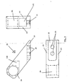
- Fig. 4 represents a first embodiment of the present invention.
- Fig. 5 represents a view of a first auxiliary element which is characteristic to the invention.
- Fig. 6 represents a second embodiment of the invention.
- FIG. 1 illustrates the type of load cell 1, to which the present invention is related. It is a load cell of the beam type.
- This type of load cell has the shape of an elongated beam, which is subjected to the load to be measured, said load causing a bending or shearing force to be exerted on the load cell.
- Most load cells of this type comprise a cavity 11, thereby creating a weakened section 12.
- the load cell 1 comprises a first part 13, to the right of section 12, and a second part 14, to the left of section 12. Even if no weakened section is present, a load cell can generally be divided into two parts, separated by a section, wherein one part is connected to the supporting structure 2, while the other is connected to the weighing structure 18.
- the load cell is subjected during weighing to a bending or shear force.
- the load cell is fixed at the first part 13 to the supporting structure 2, by two bolts 3.
- the second part 14 carries the weighing structure 18, which exerts a downward-force 4 on the load cell 1.
- a weighing device usually comprises several of such load cells, supporting a weighing structure in a number of force introduction points, for example in the four corners of a rectangular weighing platform.
- a hole 5 may be present in order to fix the weighing structure 18 to the cell.
- Strain gages are present, preferably in the cavity 11, for producing a signal which is related to the bending force. Through connection 6, the signal is transmitted to the measurement equipment (not shown).
- Most load cells of this type have a jump 19 in the thickness of the cell, which allows a deformation of the part to the left of this jump, even if the supporting structure 2 extends underneath the whole of the load cell 1.
- Figures 2 and 3 show prior art examples of how such a load cell may be implemented, in particular in case a tilted position of the supporting structure 2 is to be allowed.
- the cell is clamped to a first auxiliary element 7, by the two bolts 3.
- the first element 7 is connected to the supporting structure at point 8, through a universal joint (not shown).
- a second auxiliary element 9 is bolted to the load cell at the latter's other extremity, and the weighing structure is connected to the element 9 at point 10, through another universal joint.
- the weighing structure is thus suspended from the base frame, and the load force 4 of the weight bends the load cell downwards.
- Figure 3 shows an alternative, wherein the auxiliary elements 15 and 16 are used, which allow the connection points 17 to be placed closer together, leading to advantages in the use as a mobile weighing system.
- auxiliary element 21 is used for connecting the load cell to the supporting structure 2 (not shown).
- the element 21 is presented in more detail in figure 5. It comprises a base plate 22, to which the load cell can be fixed, preferably bolted, and two sidewalls 23, which rise up on each side of the load cell 1.
- the part 13 of the load cell which is to the right of the weakened section 12 is bolted to the base plate.
- the walls 23 are connected by a solid part 100, comprising a hole 24, whose centre line is perpendicular to the vertical walls 23.
- the element 21 is connected to the supporting structure, through a universal joint 29, placed inside the hole 24.
- the presence of the solid block 100 creates a rectangular opening 101, into which fits the load cell 1.
- the load cell 1 can be inserted into this opening, until it can be bolted to the base plate 22.
- holes 25 are present in the base plate 22.
- the load cell may be fixed to the base plate 22 in any other way known in the art.
- the load cell and the element 21 form a homogenous block.
- the sidewalls 23 preferably have an oblique position (see angle ⁇ ) with respect to the base plate 22.
- a second auxiliary element 26 may be fixed to the load cell, by bolt 27, and is connected to the weighing structure, in point 28, by a universal joint 32.
- the points 30 and 28 are placed on the same vertical line. However, small deviations from this situation are possible without departing from the scope of the invention.
- the point 30 should in any case be positioned on the side of the section 12 which is opposite the part 13.
- the same element 21 can be used in a design which is rotated 180° with respect to the one shown in figure 4.
- the supporting structure is connected at point 28, to the auxiliary element 26, while the weighing structure is connected to the element 21, at point 30.
- the element 21 may be produced in a form which differs from the one shown in figures 4 and 5.
- the basic characteristics are the base plate 22, and the side walls 23.
- the walls need not be connected at the top by a solid block 100. They may simply comprise holes or other means which ensure that the element can be properly connected to either the supporting frame or the weighing frame, in a point opposite the part 13.
- the walls 23 may have a cross section which is different from that of a straight vertical wall. They may be adapted to a special shape of the applied load cell.
- figure 4 allows a load to be weighed in a tilted position, due to the presence of the universal joints. Furthermore, the deformation of the load cell 1 while weighing is such that the part 14 of the load cell is bent downwards with respect to the base plate 22 (or the base plate 22 and the part 13 are bent downwards with respect to the part 14, in the case of the 180° rotated position). This way of bending ensures that the strain in bolt 20 remains virtually unchanged during deformation. This is the ideal way of deforming the cell, which improves the accuracy of the measurement.
- FIG. 6 shows an alternative embodiment, which is however equivalent to the one shown in figure 4.
- the load cell 40 now has a horizontal bore 31 to which the weighing structure can be suspended, preferably through a universal joint. This renders the use of a second auxiliary element 26 superfluous.
- the sidewalls of the element 21 have a somewhat different shape, which is of course totally equivalent to the one shown in figure 4.
- the present invention is related to a weighing device equipped with at least one load cell 1 of the beam type which is installed by way of an auxiliary element having the form of element 21.
- the invention is equally related to the element 21 itself, to be used in combination with a load cell of the beam type.
Landscapes
- Physics & Mathematics (AREA)
- General Physics & Mathematics (AREA)
- Measurement Of Force In General (AREA)
- Weight Measurement For Supplying Or Discharging Of Specified Amounts Of Material (AREA)
- Maintenance And Inspection Apparatuses For Elevators (AREA)
Claims (11)
- Dispositif pour peser une charge, comprenant une structure de support (2), une structure de pesage (18) et une ou plusieurs cellules de charge (1, 40) de type poutre, chaque cellule de charge comprenant une première partie (13) et une deuxième partie (14), avec une section de séparation (12) entre lesdites deux parties, une desdites parties (13, 14) étant raccordée à ladite structure de support (2), tandis que l'autre desdites parties (13, 14) est raccordée à ladite structure de pesage (18),
au moins une cellule de charge (1, 40) étant raccordée à un élément auxiliaire (21), ledit élément comprenant :- une plaque de base (22) à laquelle la première partie (13) de ladite cellule de charge est raccordée de manière rigide,- deux parois latérales (23) raccordées de manière rigide à ladite plaque de base (22) et placées de chaque côté de ladite cellule de charge lorsque la cellule de charge est fixée audit élément (21),caractérisé en ce que ledit élément auxiliaire (21) comprend en outre un moyen pour raccorder ledit élément (21) à ladite structure de support (2) ou à ladite structure de pesage (18) en un point (30) qui est placé sur le côté de ladite section de séparation (12) qui est opposé à ladite première partie (13). - Dispositif selon la revendication 1, dans lequel ledit moyen pour raccorder ledit élément (21) comprend une paire de trous dans lesdites parois latérales (23), la ligne reliant les points centraux desdits trous étant placée sur le côté de ladite section de séparation (12) qui est opposé à ladite première partie (13).
- Dispositif selon la revendication 1, dans lequel ledit moyen pour raccorder ledit élément comprend un bloc solide (100) raccordant lesdites parois (23), ledit bloc (100) comprenant un trou cylindrique (24), la ligne centrale dudit trou étant placée sur le côté de ladite section de séparation (12) qui est opposé à ladite première partie (13).
- Dispositif selon l'une quelconque des revendications précédentes, dans lequel un deuxième élément auxiliaire (26) est raccordé de manière rigide à ladite deuxième partie (14) de ladite cellule de charge.
- Dispositif selon l'une quelconque des revendications précédentes, dans lequel ledit élément auxiliaire (21) est raccordé à ladite structure de support (2) ou à ladite structure de pesage (18) par un joint universel (29).
- Dispositif selon la revendication 4, dans lequel ledit deuxième élément auxiliaire (26) est raccordé à ladite structure de support (2) ou à ladite structure de pesage (18) par un joint universel (32).
- Dispositif selon la revendication 1, dans lequel ladite cellule de charge (40) comprend un alésage (31) dans ladite deuxième partie (14), la ligne centrale dudit alésage étant essentiellement horizontale lorsque ladite cellule de charge est placée sur ladite plaque de base (22) en position essentiellement horizontale.
- Dispositif selon la revendication 7, dans lequel ladite cellule de charge (40) est raccordée à ladite structure de support (2) ou à ladite structure de pesage (18) par un joint universel.
- Dispositif selon l'une quelconque des revendications précédentes, dans lequel ladite cellule de charge est boulonnée à ladite plaque de base (22) par deux boulons (3) ou plus.
- Dispositif selon l'une quelconque des revendications précédentes, dans lequel ledit élément auxiliaire (21) et ladite cellule de charge (1, 40) forment un bloc homogène.
- Elément auxiliaire (21) pour utilisation comme élément de support d'une cellule de charge (1, 40) du type poutre, ladite cellule de charge comprenant une première partie (13) et une deuxième partie (14), avec une section de séparation (12) entre elles, ledit élément (21) comprenant :- une plaque de base (22) à laquelle la première partie (13) de ladite cellule de charge doit être raccordée de manière rigide,- deux parois latérales (23), raccordées de manière rigide à ladite plaque de base et placées des deux côtés de ladite cellule de charge lorsque la cellule de charge est fixée audit élément (21),caractérisé en ce que ledit élément auxiliaire (21) comprend en outre un moyen pour raccorder ledit élément (21) à une structure de support (2) ou à une structure de pesage (18) en un point (30) qui est placé sur le côté de la section de séparation (12) qui est opposé à ladite première partie (13).
Priority Applications (2)
| Application Number | Priority Date | Filing Date | Title |
|---|---|---|---|
| EP06075549A EP1666853A3 (fr) | 2001-07-11 | 2002-07-11 | Dispositif pour peser une charge |
| EP06075548A EP1666852A3 (fr) | 2001-07-11 | 2002-07-11 | Dispositif mobile pour peser une charge. |
Applications Claiming Priority (4)
| Application Number | Priority Date | Filing Date | Title |
|---|---|---|---|
| BE200100470 | 2001-07-11 | ||
| BE2001/0470A BE1014291A6 (nl) | 2001-07-11 | 2001-07-11 | Lastkrachtinleiding voor een weegsysteem. |
| BE2001/0655A BE1014419A6 (nl) | 2001-10-08 | 2001-10-08 | Krachtinleiding voor een weegsysteem. |
| BE200100655 | 2001-10-08 |
Related Child Applications (2)
| Application Number | Title | Priority Date | Filing Date |
|---|---|---|---|
| EP06075549A Division EP1666853A3 (fr) | 2001-07-11 | 2002-07-11 | Dispositif pour peser une charge |
| EP06075548A Division EP1666852A3 (fr) | 2001-07-11 | 2002-07-11 | Dispositif mobile pour peser une charge. |
Publications (3)
| Publication Number | Publication Date |
|---|---|
| EP1275943A2 EP1275943A2 (fr) | 2003-01-15 |
| EP1275943A3 EP1275943A3 (fr) | 2004-01-14 |
| EP1275943B1 true EP1275943B1 (fr) | 2006-03-29 |
Family
ID=25663241
Family Applications (3)
| Application Number | Title | Priority Date | Filing Date |
|---|---|---|---|
| EP06075548A Withdrawn EP1666852A3 (fr) | 2001-07-11 | 2002-07-11 | Dispositif mobile pour peser une charge. |
| EP06075549A Withdrawn EP1666853A3 (fr) | 2001-07-11 | 2002-07-11 | Dispositif pour peser une charge |
| EP02447132A Expired - Lifetime EP1275943B1 (fr) | 2001-07-11 | 2002-07-11 | Dispositif mobile pour peser une charge |
Family Applications Before (2)
| Application Number | Title | Priority Date | Filing Date |
|---|---|---|---|
| EP06075548A Withdrawn EP1666852A3 (fr) | 2001-07-11 | 2002-07-11 | Dispositif mobile pour peser une charge. |
| EP06075549A Withdrawn EP1666853A3 (fr) | 2001-07-11 | 2002-07-11 | Dispositif pour peser une charge |
Country Status (3)
| Country | Link |
|---|---|
| EP (3) | EP1666852A3 (fr) |
| AT (1) | ATE321994T1 (fr) |
| DE (1) | DE60210250T2 (fr) |
Families Citing this family (5)
| Publication number | Priority date | Publication date | Assignee | Title |
|---|---|---|---|---|
| US7361852B2 (en) | 2006-07-07 | 2008-04-22 | Mettler-Toledo Ag | Weighing module |
| US7371978B2 (en) * | 2006-07-07 | 2008-05-13 | Mettler-Toledo Ag | Thermally insulated weighing module |
| GB0625242D0 (en) * | 2006-12-19 | 2007-01-31 | Cnh Belgium Nv | Load beam for a weighing apparatus |
| NL2010270C2 (nl) | 2013-02-07 | 2014-08-11 | Ravas Europ B V | Hefwagen en heforgaan. |
| CN107941398B (zh) * | 2017-11-27 | 2023-12-08 | 苏州海德新材料科技股份有限公司 | 监测支座及智能监测系统 |
Family Cites Families (8)
| Publication number | Priority date | Publication date | Assignee | Title |
|---|---|---|---|---|
| JPS6227624A (ja) * | 1985-07-29 | 1987-02-05 | Kubota Ltd | 計重装置 |
| ATE131603T1 (de) | 1990-09-21 | 1995-12-15 | Nuyts Orb Nv | Mobiles gerät zum wiegen einer ladung |
| DE69317993T2 (de) | 1992-12-22 | 1998-10-22 | Nuyts Orb N V | Eingebaute Wägevorrichtung in einem Fahrzeug, wie ein Lastkraftwagen oder ein ähnliches Fahrzeug |
| US5773768A (en) * | 1992-12-22 | 1998-06-30 | Nv Nuyts Orb | Transport and on-board weighing device with a stabilizer thereof |
| BE1006719A7 (nl) * | 1993-02-15 | 1994-11-22 | Nuyts Orb Nv | Beschermde weegophanging. |
| NL1000432C2 (nl) * | 1995-05-24 | 1996-11-26 | Petrus Wilhelmus Maria Welvaar | Weeginrichting. |
| DE29620110U1 (de) * | 1996-11-19 | 1998-03-19 | Systa System Automation Gmbh | Wägezellenmodul |
| GB9808768D0 (en) * | 1998-04-25 | 1998-06-24 | Nova Weigh Limited | Improved weighing assembly |
-
2002
- 2002-07-11 EP EP06075548A patent/EP1666852A3/fr not_active Withdrawn
- 2002-07-11 DE DE60210250T patent/DE60210250T2/de not_active Expired - Fee Related
- 2002-07-11 AT AT02447132T patent/ATE321994T1/de not_active IP Right Cessation
- 2002-07-11 EP EP06075549A patent/EP1666853A3/fr not_active Withdrawn
- 2002-07-11 EP EP02447132A patent/EP1275943B1/fr not_active Expired - Lifetime
Also Published As
| Publication number | Publication date |
|---|---|
| DE60210250T2 (de) | 2007-03-08 |
| EP1666852A3 (fr) | 2008-05-14 |
| ATE321994T1 (de) | 2006-04-15 |
| DE60210250D1 (de) | 2006-05-18 |
| EP1666853A3 (fr) | 2008-05-07 |
| EP1666852A2 (fr) | 2006-06-07 |
| EP1666853A2 (fr) | 2006-06-07 |
| EP1275943A3 (fr) | 2004-01-14 |
| EP1275943A2 (fr) | 2003-01-15 |
Similar Documents
| Publication | Publication Date | Title |
|---|---|---|
| US4280576A (en) | Low profile tension mounted load cell industrial scale | |
| JP2004511689A (ja) | 構造の支持のために構造要素を支持するブラケット | |
| EP3551972B1 (fr) | Ensemble de lame de fourche à détection de poids à auto-compensation | |
| US4549622A (en) | Heavy duty weigh scale | |
| EP1423666B1 (fr) | Balance a ensemble socle compensateur de niveau | |
| US4078623A (en) | Scaling device for an elevator car | |
| EP1275943B1 (fr) | Dispositif mobile pour peser une charge | |
| US4828055A (en) | Weighbridge with pivotal supporting system | |
| GB2054874A (en) | Weighing apparatus | |
| EP0978714A3 (fr) | Cellule de charge | |
| EP1111353B1 (fr) | Dispositif de pesage | |
| EP0744598B1 (fr) | Appareil de pesée | |
| US4261428A (en) | Platform weighing apparatus | |
| US4733736A (en) | Load cell assembly | |
| EP0452957B1 (fr) | Arrangement pour mesurer une charge | |
| WO2002043984A3 (fr) | Ensemble capteur de poids comportant un ressort de surcharge | |
| CN112746692A (zh) | 墙板与钢梁的安装结构 | |
| EP1936334A2 (fr) | Balance à poutre de flexion | |
| JPH11211543A (ja) | ロードセルの過負荷防止装置 | |
| JPH0454002B2 (fr) | ||
| US20220267130A1 (en) | Forklift scale sensor attachment and mounting | |
| JP2507076Y2 (ja) | バ−型秤 | |
| AU773086B2 (en) | Load-measuring device for a load-bearing element of an elevator | |
| JPH025382Y2 (fr) | ||
| GB2188738A (en) | Load cell |
Legal Events
| Date | Code | Title | Description |
|---|---|---|---|
| PUAI | Public reference made under article 153(3) epc to a published international application that has entered the european phase |
Free format text: ORIGINAL CODE: 0009012 |
|
| AK | Designated contracting states |
Kind code of ref document: A2 Designated state(s): AT BE BG CH CY CZ DE DK EE ES FI FR GB GR IE IT LI LU MC NL PT SE SK TR |
|
| AX | Request for extension of the european patent |
Free format text: AL;LT;LV;MK;RO;SI |
|
| PUAL | Search report despatched |
Free format text: ORIGINAL CODE: 0009013 |
|
| AK | Designated contracting states |
Kind code of ref document: A3 Designated state(s): AT BE BG CH CY CZ DE DK EE ES FI FR GB GR IE IT LI LU MC NL PT SE SK TR |
|
| AX | Request for extension of the european patent |
Extension state: AL LT LV MK RO SI |
|
| 17P | Request for examination filed |
Effective date: 20040309 |
|
| AKX | Designation fees paid |
Designated state(s): AT BE BG CH CY CZ DE DK EE ES FI FR GB GR IE IT LI LU MC NL PT SE SK TR |
|
| 17Q | First examination report despatched |
Effective date: 20040924 |
|
| GRAP | Despatch of communication of intention to grant a patent |
Free format text: ORIGINAL CODE: EPIDOSNIGR1 |
|
| RIC1 | Information provided on ipc code assigned before grant |
Ipc: 7G 01G 21/23 B Ipc: 7G 01G 19/12 A |
|
| RIC1 | Information provided on ipc code assigned before grant |
Ipc: 7G 01G 21/23 B Ipc: 7G 01G 19/12 A |
|
| GRAS | Grant fee paid |
Free format text: ORIGINAL CODE: EPIDOSNIGR3 |
|
| GRAA | (expected) grant |
Free format text: ORIGINAL CODE: 0009210 |
|
| AK | Designated contracting states |
Kind code of ref document: B1 Designated state(s): AT BE BG CH CY CZ DE DK EE ES FI FR GB GR IE IT LI LU MC NL PT SE SK TR |
|
| PG25 | Lapsed in a contracting state [announced via postgrant information from national office to epo] |
Ref country code: IT Free format text: LAPSE BECAUSE OF FAILURE TO SUBMIT A TRANSLATION OF THE DESCRIPTION OR TO PAY THE FEE WITHIN THE PRESCRIBED TIME-LIMIT;WARNING: LAPSES OF ITALIAN PATENTS WITH EFFECTIVE DATE BEFORE 2007 MAY HAVE OCCURRED AT ANY TIME BEFORE 2007. THE CORRECT EFFECTIVE DATE MAY BE DIFFERENT FROM THE ONE RECORDED. Effective date: 20060329 Ref country code: SK Free format text: LAPSE BECAUSE OF FAILURE TO SUBMIT A TRANSLATION OF THE DESCRIPTION OR TO PAY THE FEE WITHIN THE PRESCRIBED TIME-LIMIT Effective date: 20060329 Ref country code: AT Free format text: LAPSE BECAUSE OF FAILURE TO SUBMIT A TRANSLATION OF THE DESCRIPTION OR TO PAY THE FEE WITHIN THE PRESCRIBED TIME-LIMIT Effective date: 20060329 |
|
| REG | Reference to a national code |
Ref country code: GB Ref legal event code: FG4D |
|
| REG | Reference to a national code |
Ref country code: CH Ref legal event code: EP |
|
| REG | Reference to a national code |
Ref country code: IE Ref legal event code: FG4D |
|
| REF | Corresponds to: |
Ref document number: 60210250 Country of ref document: DE Date of ref document: 20060518 Kind code of ref document: P |
|
| PGFP | Annual fee paid to national office [announced via postgrant information from national office to epo] |
Ref country code: NL Payment date: 20060626 Year of fee payment: 5 |
|
| PGFP | Annual fee paid to national office [announced via postgrant information from national office to epo] |
Ref country code: GB Payment date: 20060627 Year of fee payment: 5 |
|
| PGFP | Annual fee paid to national office [announced via postgrant information from national office to epo] |
Ref country code: BE Payment date: 20060628 Year of fee payment: 5 |
|
| PG25 | Lapsed in a contracting state [announced via postgrant information from national office to epo] |
Ref country code: SE Free format text: LAPSE BECAUSE OF FAILURE TO SUBMIT A TRANSLATION OF THE DESCRIPTION OR TO PAY THE FEE WITHIN THE PRESCRIBED TIME-LIMIT Effective date: 20060629 Ref country code: BG Free format text: LAPSE BECAUSE OF FAILURE TO SUBMIT A TRANSLATION OF THE DESCRIPTION OR TO PAY THE FEE WITHIN THE PRESCRIBED TIME-LIMIT Effective date: 20060629 Ref country code: DK Free format text: LAPSE BECAUSE OF FAILURE TO SUBMIT A TRANSLATION OF THE DESCRIPTION OR TO PAY THE FEE WITHIN THE PRESCRIBED TIME-LIMIT Effective date: 20060629 |
|
| PGFP | Annual fee paid to national office [announced via postgrant information from national office to epo] |
Ref country code: DE Payment date: 20060630 Year of fee payment: 5 |
|
| PG25 | Lapsed in a contracting state [announced via postgrant information from national office to epo] |
Ref country code: ES Free format text: LAPSE BECAUSE OF FAILURE TO SUBMIT A TRANSLATION OF THE DESCRIPTION OR TO PAY THE FEE WITHIN THE PRESCRIBED TIME-LIMIT Effective date: 20060710 |
|
| PGFP | Annual fee paid to national office [announced via postgrant information from national office to epo] |
Ref country code: CH Payment date: 20060725 Year of fee payment: 5 |
|
| PGFP | Annual fee paid to national office [announced via postgrant information from national office to epo] |
Ref country code: IE Payment date: 20060726 Year of fee payment: 5 |
|
| PG25 | Lapsed in a contracting state [announced via postgrant information from national office to epo] |
Ref country code: MC Free format text: LAPSE BECAUSE OF NON-PAYMENT OF DUE FEES Effective date: 20060731 |
|
| REG | Reference to a national code |
Ref country code: CH Ref legal event code: NV Representative=s name: BOVARD AG PATENTANWAELTE |
|
| PG25 | Lapsed in a contracting state [announced via postgrant information from national office to epo] |
Ref country code: PT Free format text: LAPSE BECAUSE OF FAILURE TO SUBMIT A TRANSLATION OF THE DESCRIPTION OR TO PAY THE FEE WITHIN THE PRESCRIBED TIME-LIMIT Effective date: 20060829 |
|
| PLBE | No opposition filed within time limit |
Free format text: ORIGINAL CODE: 0009261 |
|
| STAA | Information on the status of an ep patent application or granted ep patent |
Free format text: STATUS: NO OPPOSITION FILED WITHIN TIME LIMIT |
|
| 26N | No opposition filed |
Effective date: 20070102 |
|
| EN | Fr: translation not filed | ||
| BERE | Be: lapsed |
Owner name: *PM ON BOARD LTD Effective date: 20070731 |
|
| REG | Reference to a national code |
Ref country code: CH Ref legal event code: PL |
|
| GBPC | Gb: european patent ceased through non-payment of renewal fee |
Effective date: 20070711 |
|
| NLV4 | Nl: lapsed or anulled due to non-payment of the annual fee |
Effective date: 20080201 |
|
| PG25 | Lapsed in a contracting state [announced via postgrant information from national office to epo] |
Ref country code: CZ Free format text: LAPSE BECAUSE OF FAILURE TO SUBMIT A TRANSLATION OF THE DESCRIPTION OR TO PAY THE FEE WITHIN THE PRESCRIBED TIME-LIMIT Effective date: 20060329 Ref country code: DE Free format text: LAPSE BECAUSE OF NON-PAYMENT OF DUE FEES Effective date: 20080201 Ref country code: CH Free format text: LAPSE BECAUSE OF NON-PAYMENT OF DUE FEES Effective date: 20070731 Ref country code: LI Free format text: LAPSE BECAUSE OF NON-PAYMENT OF DUE FEES Effective date: 20070731 Ref country code: GR Free format text: LAPSE BECAUSE OF FAILURE TO SUBMIT A TRANSLATION OF THE DESCRIPTION OR TO PAY THE FEE WITHIN THE PRESCRIBED TIME-LIMIT Effective date: 20060630 Ref country code: FR Free format text: LAPSE BECAUSE OF FAILURE TO SUBMIT A TRANSLATION OF THE DESCRIPTION OR TO PAY THE FEE WITHIN THE PRESCRIBED TIME-LIMIT Effective date: 20070309 Ref country code: NL Free format text: LAPSE BECAUSE OF NON-PAYMENT OF DUE FEES Effective date: 20080201 |
|
| PG25 | Lapsed in a contracting state [announced via postgrant information from national office to epo] |
Ref country code: GB Free format text: LAPSE BECAUSE OF NON-PAYMENT OF DUE FEES Effective date: 20070711 |
|
| PG25 | Lapsed in a contracting state [announced via postgrant information from national office to epo] |
Ref country code: FI Free format text: LAPSE BECAUSE OF FAILURE TO SUBMIT A TRANSLATION OF THE DESCRIPTION OR TO PAY THE FEE WITHIN THE PRESCRIBED TIME-LIMIT Effective date: 20060329 Ref country code: EE Free format text: LAPSE BECAUSE OF FAILURE TO SUBMIT A TRANSLATION OF THE DESCRIPTION OR TO PAY THE FEE WITHIN THE PRESCRIBED TIME-LIMIT Effective date: 20060329 |
|
| PG25 | Lapsed in a contracting state [announced via postgrant information from national office to epo] |
Ref country code: LU Free format text: LAPSE BECAUSE OF NON-PAYMENT OF DUE FEES Effective date: 20060711 Ref country code: TR Free format text: LAPSE BECAUSE OF FAILURE TO SUBMIT A TRANSLATION OF THE DESCRIPTION OR TO PAY THE FEE WITHIN THE PRESCRIBED TIME-LIMIT Effective date: 20060329 |
|
| PG25 | Lapsed in a contracting state [announced via postgrant information from national office to epo] |
Ref country code: BE Free format text: LAPSE BECAUSE OF NON-PAYMENT OF DUE FEES Effective date: 20070731 |
|
| PG25 | Lapsed in a contracting state [announced via postgrant information from national office to epo] |
Ref country code: IE Free format text: LAPSE BECAUSE OF NON-PAYMENT OF DUE FEES Effective date: 20070711 |
|
| PG25 | Lapsed in a contracting state [announced via postgrant information from national office to epo] |
Ref country code: CY Free format text: LAPSE BECAUSE OF FAILURE TO SUBMIT A TRANSLATION OF THE DESCRIPTION OR TO PAY THE FEE WITHIN THE PRESCRIBED TIME-LIMIT Effective date: 20060329 Ref country code: FR Free format text: LAPSE BECAUSE OF FAILURE TO SUBMIT A TRANSLATION OF THE DESCRIPTION OR TO PAY THE FEE WITHIN THE PRESCRIBED TIME-LIMIT Effective date: 20060329 |