EP1275611A1 - Scherenhubtisch - Google Patents
Scherenhubtisch Download PDFInfo
- Publication number
- EP1275611A1 EP1275611A1 EP02013477A EP02013477A EP1275611A1 EP 1275611 A1 EP1275611 A1 EP 1275611A1 EP 02013477 A EP02013477 A EP 02013477A EP 02013477 A EP02013477 A EP 02013477A EP 1275611 A1 EP1275611 A1 EP 1275611A1
- Authority
- EP
- European Patent Office
- Prior art keywords
- force
- exerting
- attachment point
- movable element
- curve
- Prior art date
- Legal status (The legal status is an assumption and is not a legal conclusion. Google has not performed a legal analysis and makes no representation as to the accuracy of the status listed.)
- Granted
Links
Images



Classifications
-
- B—PERFORMING OPERATIONS; TRANSPORTING
- B66—HOISTING; LIFTING; HAULING
- B66F—HOISTING, LIFTING, HAULING OR PUSHING, NOT OTHERWISE PROVIDED FOR, e.g. DEVICES WHICH APPLY A LIFTING OR PUSHING FORCE DIRECTLY TO THE SURFACE OF A LOAD
- B66F7/00—Lifting frames, e.g. for lifting vehicles; Platform lifts
- B66F7/06—Lifting frames, e.g. for lifting vehicles; Platform lifts with platforms supported by levers for vertical movement
- B66F7/08—Lifting frames, e.g. for lifting vehicles; Platform lifts with platforms supported by levers for vertical movement hydraulically or pneumatically operated
-
- B—PERFORMING OPERATIONS; TRANSPORTING
- B66—HOISTING; LIFTING; HAULING
- B66F—HOISTING, LIFTING, HAULING OR PUSHING, NOT OTHERWISE PROVIDED FOR, e.g. DEVICES WHICH APPLY A LIFTING OR PUSHING FORCE DIRECTLY TO THE SURFACE OF A LOAD
- B66F7/00—Lifting frames, e.g. for lifting vehicles; Platform lifts
- B66F7/06—Lifting frames, e.g. for lifting vehicles; Platform lifts with platforms supported by levers for vertical movement
- B66F7/065—Scissor linkages, i.e. X-configuration
Definitions
- the present invention relates to an apparatus and a method for adjustment one on a movable element, e.g. B. a lift, applied force according to the The preamble of claims 1 and 4.
- a movable element e.g. B. a lift
- Scissor-like connections are used in many devices and machines, to achieve mobility, e.g. B. in lifting devices such as height adjustable Working platforms of a printing press. These scissor connections make it possible Moving a work platform or other platform from a lower, closed or retracted position in which the stage is very close to a base or the floor located or contacted, in an upper, open or extended position.
- a movable element such as a lifting platform, e.g. with a base, a floor or a working level or the frame of a machine, especially one Printing press, can be connected by the machine operator himself, by a Drive device (e.g. a motor) or by a mechanism or a Device for recycling energy is moved, in particular lifted.
- a Drive device e.g. a motor
- a mechanism or a Device for recycling energy is moved, in particular lifted.
- the force acting on the movable element must depend on the weight of the movable element, the scissor connection and, if appropriate, the lifting or load bearing or the operator to be adjustable. If no additional loads are present, the force needs only gravity and that in the mechanism itself compensate or overcome the acting friction forces.
- an energy recycling device e.g. one Gas spring mechanism for moving or lifting the element is advantageous.
- the at the Movement of the device into the lower position can release energy in one Energy recycling device may be stored e.g. a gas in A gas spring is compressed and can be used to support the movement in the upper Position can be used.
- the US 4,712,653 describes a scissor lifting mechanism for recycling Energy, a stage, a base and a pair of scissors connections with one each includes first and second scissor arms.
- a bridge structure connects the two second scissor arms with each other.
- One attached to the base and the bridge structure sealed gas cylinder moves the stage to an extended position above the base. In the sealed gas cylinder, the stage moves into the retracted position Energy stored.
- a compensation device is provided on the lifting device, which compensates for the excess force caused by the sealed gas cylinder.
- a weight adjustment mechanism which means for adjusting the radius of the force application point, i.e. the radius of the attachment point of the sealed gas cylinder on the bridge structure with respect to the attachment point of the Scissor arms at the base include the one caused by the sealed gas cylinder to compensate and distribute excess power. Therefore, the Weight adjustment mechanism can be used to fine-tune the force that is needed to hold the stage in its extended position so that the Entry process in the retracted position can be triggered in a simple manner. The weight adjustment mechanism can also be used to move up to adjust the directional force required to trigger the lifting process.
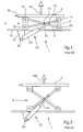
- FIG. 1 shows a known device 1 for lifting a stage 2.
- the device 1 comprises a scissor-like connection 4, which has a first scissor arm 6 and one includes second scissor arm 8 for connecting the stage 2 to a base 16.
- the Scissor arms 6 and 8 are connected to one another at a pivot point 10. On off connecting second pair of scissor arms, not shown for technical reasons additionally the stage 2 with the base 16.
- FIG. 1 shows the scissor link 4 in one closed or retracted lower position or operating mode.
- An end to the first Scissor arm 6 is attached to the stage 2 in an attachment point 12, while the the other end is movably supported by at least one roller 14.
- the Device 1 further comprises a gas spring mechanism 22 with a cylinder 24 and a piston rod 26.
- One end of the gas spring mechanism 22 is in a first Attachment point 28 attached to the scissor link 4, while the other end in a second attachment point 30 attached to a mounting plate 32 of the base 16 is.
- the gas spring mechanism 22 acts on the stage 2 with a force 34, which the Stage 2 lifting process supported. If an operator has a handle 36 on the stage 2 actuated and pulls or pushes the stage upwards, it only needs an additional force apply that is so large that the sum of the gas spring 2 and that of the operator applied force exceeds the gravity of the stage 2 and the lifting device 1.
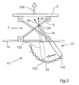
- FIG. 2 shows a known device 1 for lifting the stage 2, with the stage 2 in an upper position and the scissor link 4 in an open or extended position (upper) position or an extended operating mode.
- the gas spring 22 exercises one Force 134 on stage 2, which holds stage 2 in the upper position, i.e. the Force 134 must be equal to the gravity of the platform and the lifting device 1 or exceed these. Force 134 preferably only slightly exceeds gravity.
- the second attachment point 30 moves Gas spring 22 not because it is attached to the mounting plate 32 of the base 16.
- force 134 is less than force 34, which is the length of the respective arrow suggests.
- the on the scissor link 4 and then on the stage 2 through the The force exerted by gas spring 22 depends on the angle between piston rod 26 and the first scissor arm 6 and the compression of the gas spring.
- Both positions of the stage 2 can by means of a locking element, for. B. of a pen.
- An alternative or additional object of the present invention is to provide a Method and device for independently setting a first and a fourth on a movable element, e.g. B. a stage to create acting force.
- first force means “first force”, “second force”, “third force” and “fourth force” are used in the present description only to distinguish the forces from each other used and have no further specific meaning.
- first attachment point means to differentiate the different attachment points from each other used and have no further specific meaning.
- a method according to the invention for setting a first to a movable element exerted force in a first position of the movable element by means of a A device for exerting a force, the device for exerting a force exerts a second force on the movable element when the latter is in a second Position is; the movable element with a scissor connection Base element is connected; the device for exerting a force in a first Attachment point is attached to the scissors connection; and the device for Exerting a force in a second attachment point is attached to the base member; is characterized in that at least one of the two fastening points along a curve suitable for exerting a constant force is moved so that the second force remains constant when the first force changes.
- the method according to the invention advantageously allows wear or tear manufacturing-related deviations in force of the device for exerting a force, for. B. the gas spring to compensate.
- the method according to the invention offers one Machine operators the opportunity to apply the required force, e.g. the lifting force on their Set preferences or needs.
- the method according to the invention can also provide a further device for exerting a force which is in the first position of the movable Element exerts a third force on the movable element and in the second position of the movable element exerts a fourth force on the movable element.
- the further one Device for exerting a force can be in a third attachment point on the Scissor connection are attached, and the further device for exercising Force can be attached to the base at a fourth attachment point.
- the fourth force exerted on a movable element in its second position can be adjusted be by the third and / or the fourth attachment point along a to Exercise a constant force suitable curve is moved so that the third force remains constant when the fourth force changes.
- the at least one attachment point can be used to exercise a approximately constant force suitable curve are moved.
- FIG. 1 Another embodiment of a method according to the invention for independent Setting a first and fourth force exerted on a stage is characterized by this that the stage is connected to a base element via a scissor connection, that a first gas spring in a first attachment point on the scissor connection and is attached to the base element in a second attachment point, that a second Gas spring in a third attachment point on the scissor link and in one fourth attachment point is attached to the base that by means of the first gas spring the stage in an upper position a first force and in a lower position one second force is exerted on the stage in the upper by means of the second gas spring Position a third force and in the lower position a fourth force is exerted on that the first and / or the second attachment point along one to exercise a constant force suitable curve is moved so that the second force at a Change in the first force remains constant, and that the third and / or the fourth Attachment point along a curve suitable for exerting a constant force is moved so that the third force is constant when the
- a device for adjusting a movable element exerted force with a movable element, a base element, the one Base element with the movable element connecting scissors connection and a device for exerting a first force on the in a first position located movable element and to exert a second force on the in a second position movable element, wherein the device for exercising a force in a first attachment point on the scissor link and in one second attachment point is attached to the base member, and wherein the first Attachment point and / or the second attachment point along one for exercise a constant force suitable curve is movable so that when changing the first force the second force remains constant.
- the device according to the invention can advantageously be used for the Movement of the movable element, e.g. a lifting platform.
- the Movement of the movable element can be done manually by a machine operator caused. If the platform is moved to an upper position, the operator can Climb up, or else the stage can be used to lift loads or operators be used.
- the movable element can e.g. be designed as a stage, and the first position can be an upper position and the second position a lower position.
- the stage can be used as a work lift or a load platform Printing machine be formed, wherein the base member part of a working plane of the Printing press can be.
- the scissors connection include at least two pairs of scissor arms, each at one end with the Stage or the base element is connected.
- the force applying device may e.g. as a gas spring, a spiral spring, a compressed air cylinder, a pneumatic cylinder or a hydraulic cylinder.
- means for moving the first and / or second attachment point along the for exercise a constant force suitable curve can be provided which e.g. one along one curved slot movable fastener can include.
- the curved slot can be the one suitable for exerting a constant force Correspond to curve or be designed as a straight slot.
- the second attachment point a mounting plate pivotally attached to the base element with a two-ended slot for receiving a pin, the both ends and the slot limit the pivoting movement of the mounting plate.
- the device for exerting a force can be pivoted on the fastening plate be attached.
- Another device for setting a movable one Stage exerted in a printing press with a part of a working plane of the printing machine forming base element, a scissor connection, which the Movable platform connects to the base element and at least two pairs of scissor arms comprises, and with a gas spring, which a first force on the in an upper position located movable stage and a second force on the in a lower position exercise movable stage, the gas spring in a first Attachment point on the scissors connection and in a second attachment point the base member is attached, the second attachment point along a to Exercise a constant force suitable curve is movable so that the second force when the first force changes, remains constant.
- the device according to the invention can also be a further device for exercising include a force which is a third force on that in the first position movable element and a fourth force on the one in the second position exerts movable element, the further device for exerting a force in a third attachment point to the scissor link and a fourth Attachment point is attached to the base member, the third and / or fourth Attachment point along a curve suitable for exerting a constant force is movable so that the second force is constant when the first force changes remains.
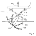
- the Device 101 includes a scissor link 4 that points to that shown in FIGS. 1 and 2 Way connects the stage 2 and a base 16, which is part of a working level Printing machine or a folder.
- 3 is the first Attachment point 28 of the gas spring 22 stationary, while the second attachment point 130 is movable along a curve 38.
- Positions shown for the attachment point can also be infinitely adjustable, so that a results in a continuous sequence of attachment points.
- the second attachment point 130 can e.g. are moved along the curve 38 into a position 230, so that the Gas spring 22 is in a position 122, which is indicated by the dashed lines is.
- the shape of curve 38 is as follows:
- the second attachment point 130 is like this arranged that the piston rod 26 extends perpendicular to the first scissor arm 6 and the force 40 acting on the first scissor arm 6 is only one perpendicular to the first scissor arm 6 has running component.
- the compression of the gas spring 22 is preset so that a given resultant force 234 acts on the stage 2 like is indicated by arrow 234.
- the first attachment point in the Position 230 moves, which result from it acting on the stage 2 Power, as indicated by arrow 234.
- the gas spring 22 in position 122 exerts a force 42 on the first scissor arm 6, which acts on the stage 2 force 234. All positions of the first attachment point 130 along the Curve 38, e.g.
- curve 38 accordingly corresponds to a constant force, i.e. the force exerted on stage 2 remains constant when the attachment point 130 moves along the curve 38.
- the shape of curve 38 can e.g. calculated using a computer program or can be determined experimentally.
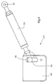
- the second fastening point of the gas spring 22 is in a position 330, which through the intersection of a first to exert a constant force suitable curve 138 and a second curve suitable for exerting a constant force Curve 238 is formed.
- the first curve suitable for exerting a constant force 138 results, like the one shown in FIG. 3, suitable for exerting a constant force Curve 38, while the second curve 238 suitable for applying a constant force arises in the opposite way, i.e. starting from the position of the gas spring 22, in the gas spring 22 extends perpendicular to the first scissor arm 6 when the Scissor link 4 is in the closed (lower) position. This position corresponds to the lower position of the stage 2.
- the compression of the gas spring 22 is then preset such that, similar to the force 34 shown in FIG. 1, a predetermined force is achieved, and the second attachment point of the gas spring 22 is moved so that in Dependence on the between the piston rod 26 and the first scissor arm 6 in closed state formed angle and the compression of the gas spring 22 the resulting force exerted on the stage 2 in the lower position remains constant.
- the Intersection 330 of the two curves 138 suitable for exerting a constant force, 238 defines the required second attachment point for the gas spring 22 to which the The predetermined upper force 234 acting on the platform in its upper position and that on the Stage in its lower position to reach the predetermined lower force (see force 34, FIG. 1).
- the force 234 acting on the stage 2 shown in its upper position in FIG. 4 and the force 34 acting on the stage 2 in its lower position (see FIG. 1) can be independent from each other by the second attachment point of the gas spring 22nd is moved along curve 238 or 138 suitable for exerting a constant force becomes.
- the attachment point 130 or 330 of the gas spring 22 can on the base 16 or Fastening plate 32 of the base 16 can be fastened (see, for example, FIG. 1).
- FIG. 5 shows the lifting device shown in FIG. 3, in which the fastening point 130 of the Gas spring 22 along a suitable for exerting an approximately constant force Curve 338 is movable.
- the curves suitable for exerting a constant force by means of a computer be calculated.
- the necessary adjustments to the force 234 and the lower force (similar to the force 34 shown in FIG. 1) in the upper or lower Positions are usually very low; therefore the second attachment point needs 130 of gas spring 22 does not necessarily have to be exercised along the entire constant force suitable curve 38 are moved, but possibly only along a portion of curve 38.
- This portion may be an approximation curve 338, e.g. B. can be formed as a rectilinear curve or a second order curve.
- the approximation curve 338 can be calculated by means of a computer. B. be a tangent to curve 38 at point 130.
- a device 101 can be used to independently adjust both forces. as shown in Fig. 6.
- a second gas spring 222 is arranged in addition to a first gas spring 122 Fastening point 28 of the scissor arm 6, a second gas spring 222 is arranged.
- the on the Stage 2 in the upper position applied force 334 is the sum of the resulting first force 336 which the first gas spring 122 exerts on the stage 2, and the resulting third force 436, which the second gas spring 222 exerts on the stage 2.
- the second fastening point 430 of the first gas spring can be used to set the force 334 122 along the second curve 238 suitable for exerting a constant force be moved. This movement leads to a change in the first force 336 what subsequently causes a change in force 334.
- both gas springs 122 and 222 also apply a force to the stage 2 when it is in the lower position located. These two forces can be added to a resulting force.
- the fourth fastening point 530 can change this resulting force second gas spring 222 along the first suitable for exerting a constant force Curve 138 are moved, resulting in a change of fourth to stage 2 in their force exerted in the lower position, the third force 436 remaining constant.
- Fig. 7 shows a mounting plate 44, which is at a pivot point 46 at the base or a base element is arranged.
- the fastening plate 44 comprises a slot or an elongated hole 48; the base 16 includes a pin 50 which is connected to the slot 48 cooperates to limit the movement of the mounting plate 44.
- the gas spring 22 is pivotally attached to the mounting plate in the cylinder mounting point 52. A rotation of the mounting plate 44 about the pivot point 46 takes place within the through the slot 48 and the pin 50 predetermined limits and moves the Cylinder attachment point 52 along the appropriate one to apply a constant force Curve 38.
- FIG. 8 shows the first gas spring 122 with a fastening point 430, which is a plate 54 includes.
- the plate 54 has a slot or an elongated hole 56 which one for Exercise forms an approximately constant force suitable curve and in the one Fastening element 58 is movable. Movement of fastener 58 along that formed by slot 56 to exert an approximately constant force suitable curve causes a change in the angle between the gas spring 122 and the scissor arm, to which the gas spring is attached at attachment point 60, and changed at the same time the compression of the gas spring 122. Therefore, it remains on the movable Element in a first position exerted constant force when on resultant force exerted by this movable element in a second position is changed.
- FIG. 9 shows the second gas spring 222 with an attachment point 530.
- a slot or Elongated hole 156 in a plate 154 corresponds approximately to one for exercising constant force suitable curve, so that on the movable element in the second Position applied force by movement of a fastener 158 within the limitation by the gap 156 is not changed while that on the movable Element in the first position applied force is changed, being on the movable Element, the second gas spring 222 is arranged in the attachment point 160.
- FIGS. 8 and 9 can be used to operate on one and the same movable element, e.g. the stage 2 shown in Fig. 6, in a first and a second position acting forces independently.
- curve in the present application denotes a curve with a any shape, e.g. also a straight line.
- a "curve suitable for exerting a constant force” closes after the here definition used to exert an approximately constant force suitable curve, e.g. also a straight line.
- the deviation of the straight line from the exact curve is approx. 4%, where the percentage is defined as X / L.
- L is half the length of the straight line and X is the distance between an end point of the straight line and the exact curve.
- the acceptable deviation from the ideal curve can be much more than 4%, but preferably less than 25%, especially if a weaker one Gas spring is used.
- the change is the second Force only about 5% of the change in the first force. Therefore, an operator can Use a device with a straight slot to make small changes in the first force because the corresponding change in the second force is only 5% is and is usually negligible in practice. In this case, the straight line successfully replace the exact curve.
- attachment point also includes means for Attaching a force application device to a base member, e.g. a Fastening plate, a mounting element, a pin or a slot.
- base and “base element” used here do not only refer to a separate element on which e.g. a gas spring can be attached, but can be also on a machine, e.g. on a printing press or folder, as well as on the structure or frame of such a machine and on work platforms or Get platforms.
Landscapes
- Life Sciences & Earth Sciences (AREA)
- Engineering & Computer Science (AREA)
- Geology (AREA)
- Mechanical Engineering (AREA)
- Structural Engineering (AREA)
- Screen Printers (AREA)
- Manipulator (AREA)
- Feeding Of Articles By Means Other Than Belts Or Rollers (AREA)
- Handcart (AREA)
- High-Pressure Fuel Injection Pump Control (AREA)
Abstract
Description
- Fig. 1
- eine schematische Seitenansicht einer bekannten Vorrichtung zum Heben einer Hebebühne, die hier in einer unteren Position dargestellt ist;
- Fig. 2
- eine schematische Seitenansicht einer bekannten Vorrichtung zum Heben einer Hebebühne, die hier in einer oberen Position dargestellt ist;
- Fig. 3
- eine schematische Seitenansicht der erfindungsgemäßen Vorrichtung zum Einstellen einer auf eine Bühne wirkenden Kraft, bei der der Befestigungspunkt einer Gasfeder entlang einer zur Ausübung einer konstanten Kraft geeigneten Kurve bewegbar ist;
- Fig. 4
- eine schematische Seitenansicht der in Fig. 3 gezeigten Vorrichtung, bei der der Befestigungspunkt der Gasfeder entlang einer von zwei zur Ausübung einer konstanten Kraft geeigneten Kurven bewegbar ist;
- Fig. 5
- eine schematische Seitenansicht der in Fig. 3 gezeigten Vorrichtung, bei der der Befestigungspunkt der Gasfeder entlang einer zur Ausübung einer näherungsweise konstanten Kraft geeigneten Kurve bewegbar ist;
- Fig. 6
- eine schematische Seitenansicht einer erfindungsgemäßen Vorrichtung zum unabhängigen Einstellen von zwei auf eine Bühne wirkenden Kräften, in der die Befestigungspunkte einer ersten und zweiten Gasfeder entlang zur Ausübung einer konstanten Kraft geeigneten Kurven bewegbar sind;
- Fig. 7
- eine detaillierte schematische Seitenansicht eines Befestigungspunkts der Gasfeder, wobei der Befestigungspunkt eine Befestigungsplatte umfasst;
- Fig. 8
- eine detaillierte schematische Seitenansicht eines Befestigungspunkts der ersten Gasfeder, der entlang einer zur Ausübung einer konstanten Kraft geeigneten Kurve bewegbar ist;
- Fig. 9
- eine detaillierte schematische Seitenansicht eines Befestigungspunkts der zweiten Gasfeder, der entlang einer zur Ausübung einer konstanten Kraft geeigneten Kurve bewegbar ist.
- 1
- Hebevorrichtung (Stand der Technik)
- 2
- Bühne
- 4
- Scherenverbindung
- 6
- erster Scherenarm
- 8
- zweiter Scherenarm
- 10
- Schwenkpunkt
- 12
- Befestigungspunkt
- 14
- Rolle
- 16
- Basis
- 18
- Befestigungspunkt
- 20
- Rolle
- 22
- Gasfeder
- 24
- Zylinder
- 26
- Kolbenstange
- 28
- Befestigungspunkt
- 30
- Befestigungspunkt
- 32
- Befestigungsplatte
- 34
- Kraft
- 36
- Griff
- 38
- zur Ausübung einer konstanten Kraft geeignete Kurve
- 40
- Kraft
- 42
- Kraft
- 44
- Befestigungsplatte
- 46
- Schwenkpunkt
- 48
- Schlitz
- 50
- Stift
- 52
- Zylinderbefestigungspunkt
- 54
- Platte
- 56
- Schlitz
- 58
- Befestigungselement
- 60
- Befestigungspunkt
- 101
- Vorrichtung zum Einstellen einer Kraft
- 122
- Gasfederposition
- 122
- Gasfeder
- 130
- Befestigungspunkt
- 134
- Kraft
- 138
- zur Ausübung einer konstanten Kraft geeigneten Kurve
- 154
- Platte
- 156
- Schlitz
- 158
- Befestigungselement
- 222
- Gasfeder
- 230
- Position des Befestigungspunkts
- 234
- resultierende Kraft
- 238
- zur Ausübung einer konstanten Kraft geeignete Kurve
- 330
- Position des Befestigungspunkts
- 334
- Kraft
- 336
- resultierende erste Kraft
- 338
- zur Ausübung einer näherungsweise konstanten Kraft geeignete Kurve
- 430
- Befestigungspunkt
- 436
- resultierende dritte Kraft
- 530
- Befestigungspunkt
Claims (12)
- Verfahren zum Einstellen einer ersten auf ein bewegbares Element (2) ausgeübten Kraft (134, 234, 334) in einer ersten Position des bewegbaren Elements (2) mittels einer Vorrichtung zum Ausüben einer Kraft (22, 122, 222);
wobei die Vorrichtung (22, 122, 222) zum Ausüben einer Kraft eine zweite Kraft (34) auf das bewegbare Element (2) ausübt, wenn sich letzteres in einer zweiten Position befindet;das bewegbare Element (2) über eine Scherenverbindung (4) mit einem Basiselement (16) verbunden wird;die Vorrichtung zum Ausüben einer Kraft (22, 122, 222) in einem ersten Befestigungspunkt (28) an der Scherenverbindung (4) befestigt wird; unddie Vorrichtung zum Ausüben einer Kraft (22, 122, 222) in einem zweiten Befestigungspunkt (30, 130, 230, 330, 430, 530) am Basiselement (16) befestigt wird;
dadurch gekennzeichnet, dass mindestens einer der beiden Befestigungspunkte (28, 30, 130, 230, 330, 430) entlang einer zur Ausübung einer konstanten Kraft geeigneten Kurve (38, 138, 238, 338) bewegt wird, so dass die zweite Kraft (34, 134, 234, 334) bei einer Veränderung
der ersten Kraft (34, 134, 234, 334) konstant bleibt. - Verfahren nach Anspruch 1,
dadurch gekennzeichnet, dass eine weitere Vorrichtung zum Ausüben einer Kraft (222) vorgesehen ist, welche in der ersten Position des bewegbaren Elements (2) eine dritte Kraft (436) auf das bewegbare Element (2) ausübt und in der zweiten Position des bewegbaren Elements (2) eine vierte Kraft auf das bewegbare Element (2) ausübt;
dass die weitere Vorrichtung zum Ausüben einer Kraft (222) in einem dritten Befestigungspunkt (28) an der Scherenverbindung (4) befestigt wird;
dass die weitere Vorrichtung zum Ausüben einer Kraft (222) in einem vierten Befestigungspunkt (530) an der Basis (16) befestigt wird;
dass die vierte auf ein bewegbares Element (2) in dessen zweiter Position ausgeübte Kraft (34, 134, 234, 334) verstellt wird, indem der dritte und/oder der vierte Befestigungspunkt (28, 530) entlang einer zur Ausübung einer konstanten Kraft geeigneten Kurve (138) bewegt wird, so dass die dritte Kraft (436) bei einer Veränderung der vierten Kraft konstant bleibt. - Verfahren nach Anspruch 1 oder 2,
dadurch gekennzeichnet, dass der mindestens eine Befestigungspunkt (28, 30, 130, 230, 330, 530) entlang einer zur Ausübung einer näherungsweise konstanten Kraft geeigneten Kurve (38, 138, 238, 338) bewegt wird. - Vorrichtung zum Einstellen einer auf ein bewegbares Element (2) ausgeübten Kraft (34, 134, 234, 334) mit einem bewegbaren Element (2), einem Basiselement (16), einer das Basiselement (16) mit dem bewegbaren Element (2) verbindenden Scherenverbindung (4), und mit einer Vorrichtung (22, 122, 222) zum Ausüben einer ersten Kraft (134, 234, 334) auf das in einer ersten Position befindliche bewegbare Element (2) und zum Ausüben einer zweiten Kraft (34) auf das in einer zweiten Position befindliche bewegbare Element (2), wobei die Vorrichtung (22, 122, 222) zum Ausüben einer Kraft in einem ersten Befestigungspunkt (28) an der Scherenverbindung (4) und in einem zweiten Befestigungspunkt (30, 130, 230, 330, 430, 530) an dem Basiselement (16) befestigt ist; und wobei
der erste Befestigungspunkt (28) und/oder der zweite Befestigungspunkt (30, 130, 230, 330, 430, 530) entlang einer zur Ausübung einer konstanten Kraft geeigneten Kurve (38, 138, 238, 338) bewegbar ist, so dass bei einer Veränderung der ersten Kraft (134, 234, 334) die zweite Kraft (34) konstant bleibt. - Vorrichtung nach Anspruch 4,
dadurch gekennzeichnet, dass das bewegbare Element (2) als eine Bühne, insbesondere eine Arbeitsbühne und/oder Lastbühne einer Druckmaschine ausgebildet ist, und dass die erste Position eine obere Position und die zweite Position eine untere Position ist. - Vorrichtung nach einem der Ansprüche 4 oder 5,
dadurch gekennzeichnet, dass die Scherenverbindung (4) mindestens zwei Paar Scherenarme (6, 8) umfasst, von denen jeder an einem Ende mit der Bühne (2) oder dem Basiselement (16) verbunden ist. - Vorrichtung nach einem der Ansprüche 4 bis 6,
dadurch gekennzeichnet, dass die Vorrichtung (22, 122, 222) zum Ausüben einer Kraft als eine Gasfeder, eine Spiralfeder, ein Druckluftzylinder, ein Pneumatikzylinder oder ein Hydraulikzylinder ausgebildet ist. - Vorrichtung nach einem der Ansprüche 4 bis 7,
gekennzeichnet durch
Mittel zum Bewegen des ersten und/oder zweiten Befestigungspunkts (28, 30, 130, 230, 330, 430, 530) entlang der zur Ausübung einer konstanten Kraft geeigneten Kurve (38, 138, 238, 338). - Vorrichtung nach Anspruch 8,
dadurch gekennzeichnet, dass die Mittel zum Bewegen des ersten und/oder zweiten Befestigungspunkts (28, 30, 130, 230, 330, 430, 530) ein entlang einem kurvenförmigen, insbesondere einem geraden Schlitz (48, 56, 156) bewegbares Befestigungselement (50, 58, 158) umfassen. - Vorrichtung nach Anspruch 9,
dadurch gekennzeichnet, dass der kurvenförmige Schlitz (48, 56, 156) der zur Ausübung einer konstanten Kraft geeigneten Kurve (38, 138, 238, 338) entspricht. - Vorrichtung nach einem der Ansprüche 4 bis 10,
dadurch gekennzeichnet, dass der zweite Befestigungspunkt (30, 130, 230, 330, 430, 530) eine schwenkbar am Basiselement (16) befestigte Befestigungsplatte (44, 54, 154) mit einem zwei Enden umfassenden Schlitz (48, 56, 156) zur Aufnahme eines Stifts (50, 58, 158) umfasst, wobei die beiden Enden und der Schlitz (48, 56, 156) die Schwenkbewegung der Befestigungsplatte (44) begrenzen, und dass die Vorrichtung (22, 122, 222) zum Ausüben einer Kraft schwenkbar an der Befestigungsplatte (44) befestigt ist. - Druckmaschine, insbesondere Rollenrotationsdruckmaschine,
gekennzeichnet durch
eine Vorrichtung nach einem der Ansprüche 4 bis 11.
Applications Claiming Priority (2)
| Application Number | Priority Date | Filing Date | Title |
|---|---|---|---|
| US09/901,255 US6672430B2 (en) | 2001-07-09 | 2001-07-09 | Device and method for adjusting a force applied to a movable element |
| US901255 | 2001-07-09 |
Publications (2)
| Publication Number | Publication Date |
|---|---|
| EP1275611A1 true EP1275611A1 (de) | 2003-01-15 |
| EP1275611B1 EP1275611B1 (de) | 2006-08-30 |
Family
ID=25413824
Family Applications (1)
| Application Number | Title | Priority Date | Filing Date |
|---|---|---|---|
| EP02013477A Expired - Lifetime EP1275611B1 (de) | 2001-07-09 | 2002-06-17 | Scherenhubtisch |
Country Status (4)
| Country | Link |
|---|---|
| US (1) | US6672430B2 (de) |
| EP (1) | EP1275611B1 (de) |
| AT (1) | ATE338007T1 (de) |
| DE (2) | DE10226951A1 (de) |
Cited By (1)
| Publication number | Priority date | Publication date | Assignee | Title |
|---|---|---|---|---|
| NL1026457C2 (nl) * | 2004-06-18 | 2005-12-20 | Tecview Europ B V | Inklapbare schaarconstructie. |
Families Citing this family (22)
| Publication number | Priority date | Publication date | Assignee | Title |
|---|---|---|---|---|
| US20070266912A1 (en) * | 2003-04-29 | 2007-11-22 | Swain Stephen C | Multi-Position Work Tables |
| US20050045426A1 (en) * | 2003-09-02 | 2005-03-03 | Jean-Marie Rennetaud | Elevator with a scissor lift mechanism and a spring member serving as virtual counter weight |
| US8191865B2 (en) | 2004-05-17 | 2012-06-05 | Stertil B.V. | Device and system for lifting a motor vehicle |
| US7654208B2 (en) * | 2005-02-17 | 2010-02-02 | Christine Hundertpfund | Multi-positionable work surface |
| US20080218043A1 (en) * | 2006-11-15 | 2008-09-11 | Angelo Gianelo | Drawer guidance mechanism |
| US8469152B2 (en) * | 2007-09-25 | 2013-06-25 | Hunter Engineering Company | Methods and systems for multi-capacity vehicle lift system |
| US8714524B2 (en) * | 2009-12-16 | 2014-05-06 | Herkules Equipment Corporation | Belt-driven transportation system |
| US8662477B2 (en) * | 2009-12-16 | 2014-03-04 | Herkules Equipment Corporation | Belt-driven transportation system |
| US8733508B2 (en) | 2010-04-02 | 2014-05-27 | Herkules Equipment Corporation | Scissor lift assembly |
| AU2011250605B2 (en) | 2010-05-05 | 2016-06-16 | Allsteel Inc. | Moveable and demountable wall panel system for butt-glazed wall panels |
| US20120223540A1 (en) * | 2011-03-01 | 2012-09-06 | L&W Engineering, Inc. | Recreational Vehicle Lift Mechanism |
| US9422142B2 (en) | 2013-08-01 | 2016-08-23 | Herkules Equipment Corporation | Scissor-type lift assembly |
| US10244861B1 (en) | 2015-01-24 | 2019-04-02 | Nathan Mark Poniatowski | Desktop workspace that adjusts vertically |
| US9474365B2 (en) * | 2015-03-20 | 2016-10-25 | General Electric Company | Tandem spring system |
| CN108024625B (zh) * | 2015-09-24 | 2021-08-03 | 爱格升公司 | 高度可调节装置 |
| CN108136586A (zh) * | 2015-10-27 | 2018-06-08 | 松下知识产权经营株式会社 | 搬运装置 |
| TWM528117U (zh) * | 2016-05-27 | 2016-09-11 | Kelly Internat Corp | 可升降活動的支撐裝置 |
| US10258149B2 (en) * | 2016-10-18 | 2019-04-16 | Hangzhou Landa Crafts Co., Ltd. | Lifting desktop with a compact structure |
| US10893748B1 (en) | 2017-07-08 | 2021-01-19 | Office Kick, Inc. | Height adjustable desktop |
| US11338948B2 (en) * | 2017-08-02 | 2022-05-24 | Illinois Tool Works Inc. | Progressive rate case cushion |
| WO2023019477A1 (zh) | 2021-08-18 | 2023-02-23 | 南通市久正人体工学股份有限公司 | 基于人体工程优化调节辅助的升降结构及其安装方法 |
| IT202200018561A1 (it) * | 2022-09-12 | 2024-03-12 | O Me R Spa | Ponte sollevatore, particolarmente per autoveicoli. |
Citations (3)
| Publication number | Priority date | Publication date | Assignee | Title |
|---|---|---|---|---|
| US4558648A (en) * | 1983-09-20 | 1985-12-17 | Lift-R Technologies, Inc. | Energy-recycling scissors lift |
| US4712653A (en) * | 1985-08-14 | 1987-12-15 | Lift-R Technologies, Inc. | Energy-recycling scissors lift |
| JPH1160174A (ja) * | 1997-08-20 | 1999-03-02 | Printing Bureau Ministry Of Finance Japan | リフタ |
Family Cites Families (12)
| Publication number | Priority date | Publication date | Assignee | Title |
|---|---|---|---|---|
| US2829863A (en) * | 1952-07-23 | 1958-04-08 | Raymond Corp | Table of adjustable height |
| US2937852A (en) * | 1956-10-29 | 1960-05-24 | Jesse E Clarke | Lift device |
| US3110476A (en) * | 1960-03-20 | 1963-11-12 | American Mfg Company Inc | Thrust linkage supported tables |
| US3282566A (en) * | 1964-05-18 | 1966-11-01 | Autoquip Corp | Scissors operating linkage |
| US3404791A (en) * | 1965-10-18 | 1968-10-08 | Jeddeloh Bros Sweed Mills | Load-supporting apparatus |
| GB1553107A (en) * | 1975-05-17 | 1979-09-19 | Nisso Sangyo Kk | Working base elevating apparatus |
| US4526346A (en) * | 1982-01-18 | 1985-07-02 | G. W. Galloway Company, Inc. | Self-contained elevating table |
| BR8606631A (pt) * | 1985-04-16 | 1987-08-04 | Sigmund Elkuch | Equipamento de suporte |
| JPH0650477Y2 (ja) * | 1988-09-07 | 1994-12-21 | 杉安工業株式会社 | 移乗用リフトにおけるステップの起倒装置 |
| US5722513A (en) * | 1995-06-20 | 1998-03-03 | Pentalift Equipment Corporation | Scissor lift |
| US5695173A (en) * | 1996-01-11 | 1997-12-09 | Ochoa; Arturo Valencia | Scissors lift platform with electronic control |
| US6516478B2 (en) * | 2001-05-31 | 2003-02-11 | Health & Technology, Inc. | Adjustable height bed |
-
2001
- 2001-07-09 US US09/901,255 patent/US6672430B2/en not_active Expired - Fee Related
-
2002
- 2002-06-17 DE DE10226951A patent/DE10226951A1/de not_active Withdrawn
- 2002-06-17 EP EP02013477A patent/EP1275611B1/de not_active Expired - Lifetime
- 2002-06-17 DE DE50207977T patent/DE50207977D1/de not_active Expired - Lifetime
- 2002-06-17 AT AT02013477T patent/ATE338007T1/de not_active IP Right Cessation
Patent Citations (3)
| Publication number | Priority date | Publication date | Assignee | Title |
|---|---|---|---|---|
| US4558648A (en) * | 1983-09-20 | 1985-12-17 | Lift-R Technologies, Inc. | Energy-recycling scissors lift |
| US4712653A (en) * | 1985-08-14 | 1987-12-15 | Lift-R Technologies, Inc. | Energy-recycling scissors lift |
| JPH1160174A (ja) * | 1997-08-20 | 1999-03-02 | Printing Bureau Ministry Of Finance Japan | リフタ |
Non-Patent Citations (1)
| Title |
|---|
| DATABASE WPI Section PQ Week 199919, Derwent World Patents Index; Class Q38, AN 1999-225816, XP002216865 * |
Cited By (2)
| Publication number | Priority date | Publication date | Assignee | Title |
|---|---|---|---|---|
| NL1026457C2 (nl) * | 2004-06-18 | 2005-12-20 | Tecview Europ B V | Inklapbare schaarconstructie. |
| WO2005123568A1 (en) * | 2004-06-18 | 2005-12-29 | B.J. Kroese Holding B.V. | Collapsible scissor construction |
Also Published As
| Publication number | Publication date |
|---|---|
| DE10226951A1 (de) | 2003-02-13 |
| EP1275611B1 (de) | 2006-08-30 |
| DE50207977D1 (de) | 2006-10-12 |
| US20030006099A1 (en) | 2003-01-09 |
| ATE338007T1 (de) | 2006-09-15 |
| US6672430B2 (en) | 2004-01-06 |
Similar Documents
| Publication | Publication Date | Title |
|---|---|---|
| EP1275611B1 (de) | Scherenhubtisch | |
| DE69117204T2 (de) | Aufhängungseinrichtung mit einem Nockenunterstützungselement und einer federunterstützten Höhenverstellung | |
| DE69905271T2 (de) | Anordnung zum handhaben einer last | |
| AT503790B1 (de) | Anschlagvorrichtung für eine biegepresse | |
| DE29910744U1 (de) | Scherenhubtisch | |
| EP0221911B1 (de) | Wagenheber | |
| DE1777355B2 (de) | Transporteinrichtung zum Transportieren von Werkstücken zwischen zwei Pressen | |
| DE3047348C2 (de) | ||
| DE2119316A1 (de) | Aufzug für Fahrzeuge | |
| DE3875819T2 (de) | Biegepresse fuer bleche. | |
| DE10053690A1 (de) | Presse mit Linearschlitten | |
| EP0838277B1 (de) | Richtwerk zum Richten von dem Eingang einer Presse zuzuführenden Bändern | |
| DE60304403T2 (de) | Scherenhubvorrichtung | |
| EP0497780B1 (de) | Verfahren zum gegenläufigen biegen eines bleches | |
| EP1657008A1 (de) | Vorrichtung zum Zuführen eines bandförmigen Halbzeugmaterials zu einer Presse | |
| DE2704267C2 (de) | Steuervorrichtung mit einem auf einer Schwenkachse schwenkbar gelagerten Haupthebel | |
| DE69002796T2 (de) | Knopfansetzmaschine. | |
| DE3117896C2 (de) | ||
| DE3850882T2 (de) | Verstellbare Nietzange. | |
| DE2619347A1 (de) | Antriebseinrichtung fuer ein an einer geradfuehrung angeordnetes, laengs dieser geradfuehrung zu bewegendes bauteil | |
| WO2001087512A1 (de) | Transfereinrichtung und verfahren zur steuerung einer transfereinrichtung | |
| DE68902690T2 (de) | Verfahren und vorrichtung zum regeln der drehung eines elementes um eine welle durch eine schlingfeder. | |
| DE1431892B1 (de) | Im gleichgewicht bleibende trag und einstellvorrichtung | |
| DE3018997C2 (de) | Vorrichtung zum Auswechseln der Arbeitswalzen von Walzgerüsten | |
| DE1270576B (de) | Praegemaschine |
Legal Events
| Date | Code | Title | Description |
|---|---|---|---|
| PUAI | Public reference made under article 153(3) epc to a published international application that has entered the european phase |
Free format text: ORIGINAL CODE: 0009012 |
|
| AK | Designated contracting states |
Kind code of ref document: A1 Designated state(s): AT BE CH CY DE DK ES FI FR GB GR IE IT LI LU MC NL PT SE TR |
|
| AX | Request for extension of the european patent |
Free format text: AL;LT;LV;MK;RO;SI |
|
| 17P | Request for examination filed |
Effective date: 20030715 |
|
| AKX | Designation fees paid |
Designated state(s): AT BE CH CY DE DK ES FI FR GB GR IE IT LI LU MC NL PT SE TR |
|
| 17Q | First examination report despatched |
Effective date: 20031017 |
|
| RAP1 | Party data changed (applicant data changed or rights of an application transferred) |
Owner name: GOSS INTERNATIONAL AMERICAS, INC. |
|
| GRAP | Despatch of communication of intention to grant a patent |
Free format text: ORIGINAL CODE: EPIDOSNIGR1 |
|
| GRAS | Grant fee paid |
Free format text: ORIGINAL CODE: EPIDOSNIGR3 |
|
| GRAA | (expected) grant |
Free format text: ORIGINAL CODE: 0009210 |
|
| AK | Designated contracting states |
Kind code of ref document: B1 Designated state(s): AT BE CH CY DE DK ES FI FR GB GR IE IT LI LU MC NL PT SE TR |
|
| PG25 | Lapsed in a contracting state [announced via postgrant information from national office to epo] |
Ref country code: IT Free format text: LAPSE BECAUSE OF FAILURE TO SUBMIT A TRANSLATION OF THE DESCRIPTION OR TO PAY THE FEE WITHIN THE PRESCRIBED TIME-LIMIT;WARNING: LAPSES OF ITALIAN PATENTS WITH EFFECTIVE DATE BEFORE 2007 MAY HAVE OCCURRED AT ANY TIME BEFORE 2007. THE CORRECT EFFECTIVE DATE MAY BE DIFFERENT FROM THE ONE RECORDED. Effective date: 20060830 Ref country code: FI Free format text: LAPSE BECAUSE OF FAILURE TO SUBMIT A TRANSLATION OF THE DESCRIPTION OR TO PAY THE FEE WITHIN THE PRESCRIBED TIME-LIMIT Effective date: 20060830 Ref country code: IE Free format text: LAPSE BECAUSE OF FAILURE TO SUBMIT A TRANSLATION OF THE DESCRIPTION OR TO PAY THE FEE WITHIN THE PRESCRIBED TIME-LIMIT Effective date: 20060830 Ref country code: NL Free format text: LAPSE BECAUSE OF FAILURE TO SUBMIT A TRANSLATION OF THE DESCRIPTION OR TO PAY THE FEE WITHIN THE PRESCRIBED TIME-LIMIT Effective date: 20060830 |
|
| REG | Reference to a national code |
Ref country code: GB Ref legal event code: FG4D Free format text: NOT ENGLISH |
|
| REG | Reference to a national code |
Ref country code: CH Ref legal event code: EP |
|
| REG | Reference to a national code |
Ref country code: IE Ref legal event code: FG4D Free format text: LANGUAGE OF EP DOCUMENT: GERMAN |
|
| REF | Corresponds to: |
Ref document number: 50207977 Country of ref document: DE Date of ref document: 20061012 Kind code of ref document: P |
|
| PG25 | Lapsed in a contracting state [announced via postgrant information from national office to epo] |
Ref country code: SE Free format text: LAPSE BECAUSE OF FAILURE TO SUBMIT A TRANSLATION OF THE DESCRIPTION OR TO PAY THE FEE WITHIN THE PRESCRIBED TIME-LIMIT Effective date: 20061130 Ref country code: DK Free format text: LAPSE BECAUSE OF FAILURE TO SUBMIT A TRANSLATION OF THE DESCRIPTION OR TO PAY THE FEE WITHIN THE PRESCRIBED TIME-LIMIT Effective date: 20061130 |
|
| PG25 | Lapsed in a contracting state [announced via postgrant information from national office to epo] |
Ref country code: ES Free format text: LAPSE BECAUSE OF FAILURE TO SUBMIT A TRANSLATION OF THE DESCRIPTION OR TO PAY THE FEE WITHIN THE PRESCRIBED TIME-LIMIT Effective date: 20061211 |
|
| GBT | Gb: translation of ep patent filed (gb section 77(6)(a)/1977) |
Effective date: 20061212 |
|
| PG25 | Lapsed in a contracting state [announced via postgrant information from national office to epo] |
Ref country code: PT Free format text: LAPSE BECAUSE OF FAILURE TO SUBMIT A TRANSLATION OF THE DESCRIPTION OR TO PAY THE FEE WITHIN THE PRESCRIBED TIME-LIMIT Effective date: 20070212 |
|
| REG | Reference to a national code |
Ref country code: CH Ref legal event code: NV Representative=s name: KIRKER & CIE SA |
|
| NLV1 | Nl: lapsed or annulled due to failure to fulfill the requirements of art. 29p and 29m of the patents act | ||
| ET | Fr: translation filed | ||
| REG | Reference to a national code |
Ref country code: IE Ref legal event code: FD4D |
|
| PLBE | No opposition filed within time limit |
Free format text: ORIGINAL CODE: 0009261 |
|
| STAA | Information on the status of an ep patent application or granted ep patent |
Free format text: STATUS: NO OPPOSITION FILED WITHIN TIME LIMIT |
|
| 26N | No opposition filed |
Effective date: 20070531 |
|
| BERE | Be: lapsed |
Owner name: GOSS INTERNATIONAL AMERICAS, INC. Effective date: 20070630 |
|
| PG25 | Lapsed in a contracting state [announced via postgrant information from national office to epo] |
Ref country code: MC Free format text: LAPSE BECAUSE OF NON-PAYMENT OF DUE FEES Effective date: 20070630 |
|
| PG25 | Lapsed in a contracting state [announced via postgrant information from national office to epo] |
Ref country code: BE Free format text: LAPSE BECAUSE OF NON-PAYMENT OF DUE FEES Effective date: 20070630 |
|
| PG25 | Lapsed in a contracting state [announced via postgrant information from national office to epo] |
Ref country code: GR Free format text: LAPSE BECAUSE OF FAILURE TO SUBMIT A TRANSLATION OF THE DESCRIPTION OR TO PAY THE FEE WITHIN THE PRESCRIBED TIME-LIMIT Effective date: 20061201 |
|
| PG25 | Lapsed in a contracting state [announced via postgrant information from national office to epo] |
Ref country code: AT Free format text: LAPSE BECAUSE OF NON-PAYMENT OF DUE FEES Effective date: 20070617 |
|
| PG25 | Lapsed in a contracting state [announced via postgrant information from national office to epo] |
Ref country code: LU Free format text: LAPSE BECAUSE OF NON-PAYMENT OF DUE FEES Effective date: 20070617 Ref country code: CY Free format text: LAPSE BECAUSE OF FAILURE TO SUBMIT A TRANSLATION OF THE DESCRIPTION OR TO PAY THE FEE WITHIN THE PRESCRIBED TIME-LIMIT Effective date: 20060830 |
|
| PG25 | Lapsed in a contracting state [announced via postgrant information from national office to epo] |
Ref country code: TR Free format text: LAPSE BECAUSE OF FAILURE TO SUBMIT A TRANSLATION OF THE DESCRIPTION OR TO PAY THE FEE WITHIN THE PRESCRIBED TIME-LIMIT Effective date: 20060830 |
|
| PGFP | Annual fee paid to national office [announced via postgrant information from national office to epo] |
Ref country code: CH Payment date: 20110627 Year of fee payment: 10 Ref country code: FR Payment date: 20110629 Year of fee payment: 10 |
|
| PGFP | Annual fee paid to national office [announced via postgrant information from national office to epo] |
Ref country code: GB Payment date: 20110628 Year of fee payment: 10 |
|
| PGFP | Annual fee paid to national office [announced via postgrant information from national office to epo] |
Ref country code: DE Payment date: 20110629 Year of fee payment: 10 |
|
| REG | Reference to a national code |
Ref country code: CH Ref legal event code: PL |
|
| REG | Reference to a national code |
Ref country code: CH Ref legal event code: PL |
|
| GBPC | Gb: european patent ceased through non-payment of renewal fee |
Effective date: 20120617 |
|
| REG | Reference to a national code |
Ref country code: FR Ref legal event code: ST Effective date: 20130228 |
|
| REG | Reference to a national code |
Ref country code: DE Ref legal event code: R119 Ref document number: 50207977 Country of ref document: DE Effective date: 20130101 |
|
| PG25 | Lapsed in a contracting state [announced via postgrant information from national office to epo] |
Ref country code: CH Free format text: LAPSE BECAUSE OF NON-PAYMENT OF DUE FEES Effective date: 20120630 Ref country code: DE Free format text: LAPSE BECAUSE OF NON-PAYMENT OF DUE FEES Effective date: 20130101 Ref country code: LI Free format text: LAPSE BECAUSE OF NON-PAYMENT OF DUE FEES Effective date: 20120630 Ref country code: GB Free format text: LAPSE BECAUSE OF NON-PAYMENT OF DUE FEES Effective date: 20120617 Ref country code: FR Free format text: LAPSE BECAUSE OF NON-PAYMENT OF DUE FEES Effective date: 20120702 |