EP1274501B2 - Mischer - Google Patents
Mischer Download PDFInfo
- Publication number
- EP1274501B2 EP1274501B2 EP01923721A EP01923721A EP1274501B2 EP 1274501 B2 EP1274501 B2 EP 1274501B2 EP 01923721 A EP01923721 A EP 01923721A EP 01923721 A EP01923721 A EP 01923721A EP 1274501 B2 EP1274501 B2 EP 1274501B2
- Authority
- EP
- European Patent Office
- Prior art keywords
- range
- mixer
- dynamic mixer
- mixing
- materials
- Prior art date
- Legal status (The legal status is an assumption and is not a legal conclusion. Google has not performed a legal analysis and makes no representation as to the accuracy of the status listed.)
- Expired - Lifetime
Links
Images

Classifications
-
- B—PERFORMING OPERATIONS; TRANSPORTING
- B01—PHYSICAL OR CHEMICAL PROCESSES OR APPARATUS IN GENERAL
- B01F—MIXING, e.g. DISSOLVING, EMULSIFYING OR DISPERSING
- B01F27/00—Mixers with rotary stirring devices in fixed receptacles; Kneaders
- B01F27/05—Stirrers
- B01F27/07—Stirrers characterised by their mounting on the shaft
- B01F27/072—Stirrers characterised by their mounting on the shaft characterised by the disposition of the stirrers with respect to the rotating axis
- B01F27/0722—Stirrers characterised by their mounting on the shaft characterised by the disposition of the stirrers with respect to the rotating axis perpendicular with respect to the rotating axis
-
- B—PERFORMING OPERATIONS; TRANSPORTING
- B01—PHYSICAL OR CHEMICAL PROCESSES OR APPARATUS IN GENERAL
- B01F—MIXING, e.g. DISSOLVING, EMULSIFYING OR DISPERSING
- B01F27/00—Mixers with rotary stirring devices in fixed receptacles; Kneaders
- B01F27/05—Stirrers
- B01F27/07—Stirrers characterised by their mounting on the shaft
- B01F27/072—Stirrers characterised by their mounting on the shaft characterised by the disposition of the stirrers with respect to the rotating axis
- B01F27/0724—Stirrers characterised by their mounting on the shaft characterised by the disposition of the stirrers with respect to the rotating axis directly mounted on the rotating axis
-
- B—PERFORMING OPERATIONS; TRANSPORTING
- B01—PHYSICAL OR CHEMICAL PROCESSES OR APPARATUS IN GENERAL
- B01F—MIXING, e.g. DISSOLVING, EMULSIFYING OR DISPERSING
- B01F27/00—Mixers with rotary stirring devices in fixed receptacles; Kneaders
- B01F27/05—Stirrers
- B01F27/11—Stirrers characterised by the configuration of the stirrers
- B01F27/112—Stirrers characterised by the configuration of the stirrers with arms, paddles, vanes or blades
-
- B—PERFORMING OPERATIONS; TRANSPORTING
- B01—PHYSICAL OR CHEMICAL PROCESSES OR APPARATUS IN GENERAL
- B01F—MIXING, e.g. DISSOLVING, EMULSIFYING OR DISPERSING
- B01F33/00—Other mixers; Mixing plants; Combinations of mixers
- B01F33/50—Movable or transportable mixing devices or plants
- B01F33/501—Movable mixing devices, i.e. readily shifted or displaced from one place to another, e.g. portable during use
- B01F33/5011—Movable mixing devices, i.e. readily shifted or displaced from one place to another, e.g. portable during use portable during use, e.g. hand-held
-
- B—PERFORMING OPERATIONS; TRANSPORTING
- B01—PHYSICAL OR CHEMICAL PROCESSES OR APPARATUS IN GENERAL
- B01F—MIXING, e.g. DISSOLVING, EMULSIFYING OR DISPERSING
- B01F2101/00—Mixing characterised by the nature of the mixed materials or by the application field
- B01F2101/2305—Mixers of the two-component package type, i.e. where at least two components are separately stored, and are mixed in the moment of application
Definitions
- the invention relates to a device in the form of a dynamic mixer, and / or in the form of a cartridge front, which is used in the mixing of high-viscosity pastes or a combination of both devices.
- mixers are essentially suitable only for mixing relatively small amounts of easily miscible masses with not too high viscosity.
- the mixer is placed on a double cartridge in which there are two pistons.
- the power transmission to the pistons is done manually.
- the quality of the mixing result is ultimately dependent on the length of the mixing cannula and the number of spirals contained therein. Since the volume of the mixing cannula is not negligible in relation to the volume of the cartridge, there is an undesirable loss of material to be mixed or mixed when changing the mixing cannula.
- a method and a device for mixing at least two pasty masses is also in the DE 42 02 591 A1 described.
- the device comprises two containers whose Austassstutzen are arranged for common coupling to a mixer parallel to each other.
- the EP 0 993 863 A1 discloses a device in the form of a mixer with circular inlet openings, which has a bypass channel.
- DE 42 02 591 A1 discloses a device with two containers, each with an outlet, which may optionally differ from the circular shape. The mass flow exiting the device should then be directed into a static mixer. The device also has a thread for connection to the static mixer.
- EP 0 319 135 A1 There is described an apparatus for dispensing multicomponent masses comprising a multi-chamber cartridge and a static mixer.
- the static mixer has no inlet openings which correspond to the outlet openings of the cartridge.
- the static mixer is threadedly connected to the cartridge.
- the US 5,498,078 relates to a static mixer that can be connected to associated cartridges.
- the WO-98/43727 A1 describes a dynamic mixer with circular inlet openings.
- a substantially ideal mixer allows for a high material throughput while maintaining the mixing quality, on the other hand, it has a small size in order to avoid loss of material during mixing and to keep the production costs low.
- a typical dynamic mixer has two round inlet openings for the masses to be mixed, and an opening for receiving a drive shaft which drives the mixing vanes.
- the masses to be mixed are usually applied via electrically driven pistons from corresponding cartridges.
- Desired is a high throughput with consistent mixing quality.
- the amount of miscible mass per unit time is limited on the one hand by the size of the inlet openings, on the other hand by the transferable force to the piston.
- the force on the punches could be increased.
- this measure is limited by the material properties of the device in conjunction with the size of the inlet openings.
- inlet openings differently from the circular shape, it is possible to provide larger inlet openings for the materials to be mixed with the same size of the mixer or the cartridge front.
- the device in the form of a mixer or a cartridge front on the one hand sufficiently flexible and flexible to act as their own seal, on the other hand, sufficiently stable to process the forces occurring during application of the mixing compound or during mixing ,
- the material is such that it has an modulus of elasticity and an elongation at break, as described above, in combination.
- opening in the sense of the present invention means both inlet openings and outlet openings. This depends on the direction in which the substances to be mixed flow or are pressed and on whether or not openings in the mixer or the cartridge front are viewed.
- a cartridge front has at least one inlet opening, which corresponds to the at least one outlet opening.
- a mixer usually has two inlet openings and only one outlet opening.
- kidney or sickle shape in particular openings with rounded edges and corners.
- Such a design enables an optimized arrangement of the inlet openings around the opening for the drive shaft, which is usually located in the center of a dynamic mixer. Furthermore, this design allows the utilization of almost the entire surface of a dynamic mixer available for the inlet openings.
- the device according to the invention preferably has at least two, but optionally also three or four openings.
- the deviated from the circular opening usually has an area that is greater than would be possible in a circular design.
- openings are usually arranged symmetrically about the opening for the drive shaft.
- the drive of the mixing element can also be done off-center, as for example in the WO 01 / 24919A1 is described.
- the inventive device in the form of a dynamic mixer usually comprises at least three components, in particular a base plate (1), in which the non-circular inlet openings (2, 3) and the opening (4) for the drive shaft (not shown) are embedded and a rotatably mounted in the base plate (1) rotor (5) to which the mixing blades (6) are mounted and a forming groove (7) for receiving the drive shaft, and the housing (8) in which the rotor (5) runs.
- the device additionally has at least one seal in the region of the inlet openings (2, 3).
- the shape of the groove (7) for the drive shaft is arbitrary, with the proviso that a sufficient force transmission from the drive shaft to the mixing vanes (6) can take place for mixing.
- the shaping groove (7) for the drive shaft is triangular, quadrangular, square, pentagonal, hexagonal, heptagonal, octagonal or formed as a hollow pinion.
- the length and / or the diameter of the mixer are usually in the range of 5 to 1000 mm, preferably in the range of 10 to 100 mm.
- the area of the inlet openings is usually in the range of 0.1 to 5000 mm 2 , preferably in the range of 1 to 400 mm 2 .
- this adjustment is achieved by adapting the geometries of the openings of the cartridge front (10, 11) to the inlet openings (2, 3) of the mixer. This can be achieved by plug-in, snap or possibly also screw.
- the vote can also be made by adapting the materials.
- the mixer has an E-modulus in the range of 800 to 1400 N / mm 2 and / or an elongation at break in the range of 200 to 800% and the material of the cartridge front an E-modulus in the range of 2000 to 3000 N / mm 2 and / or have an elongation at break in the range of 50 to 200%.
- a comparably good sealing effect can be achieved if the material of the mixer has an modulus of elasticity in the range of 2000 to 3000 N / mm 2 and / or an elongation at break in the range of 50 to 200% and the material of the cartridge front has an E-modulus in the range from 800 to 1400 N / mm 2 and / or have an elongation at break in the range of 200 to 800%.
- Suitable materials for the device in particular in the form of a
- Mixers and / or a cartridge front with two non-circular inlet or outlet ports include PE, OPP, PP, PTFE, PC and / or POM.
- the materials are used in fiber reinforced and / or filled form.
- Suitable fibers and fillers include glass fibers / particles and carbon fibers / particles.
- Suitable mixers and / or cartridge fronts can be produced, for example, by injection molding, optionally in a 2-K injection molding process.
- the mixers and cartridge fronts according to the invention can be used in all fields of technology, in particular for mixing highly viscous, pasty and / or thick masses.
- Examples include: adhesive, joint sealants, paints.
- the mixers and cartridge fronts according to the invention can be used in the dental field.
- the devices according to the invention are particularly suitable for mixing highly viscous impression materials which are pressed out, for example, from tubular bags which are inserted into suitable cartridges with electrically driven punches. Also conceivable and possible is the application of the materials from suitable cartridges, which are filled directly with the material without a tubular bag is used.
- highly viscous masses includes all masses with a viscosity determined by consistency testing according to DIN 4823 class 0 to 3, which are measured with a diameter of less than 80 mm.
- silicones examples include silicones, polyethers, polyether silicones, epoxides and polyurethanes.
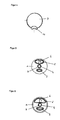
- Figure 1 shows the device in the form of a dynamic mixer in longitudinal section.
- Figure 2 shows the device in the form of a dynamic mixer in the plan.
- Figure 3 shows the device comprising a mixer and a cartridge front.
- FIG. 4 shows the embodiment in the form of a cartridge front in the top view.
- FIGS. 5 and 6 show further embodiments of a dynamic mixer in the top view.
- Figure 1 shows the device according to the invention in the form of a dynamic mixer with the three components, base plate (1) in which the non-circular inlet openings (2,3) and the opening (4) for the drive shaft are embedded, one in the base plate (1 ) rotatably mounted rotor (5) to which the mixing vanes (6) are mounted, wherein the opening has a shaping groove (7) for receiving the drive shaft, and the housing (9) in which the rotor (5) runs.
- FIG. 2 shows the device according to the invention in the form of a dynamic mixer with two kidney-shaped inlet openings of different sizes (2, 3) and a round opening (4) with a hexagonal shaped groove (7) for the drive shaft. Also indicated is the mixing blade (6) to be seen here in opening (2).
- FIG. 3 shows the device according to the invention, comprising the mixer according to FIG. 1 in conjunction with two cartridge fronts (9, 9 ').
- the two differently sized inlet openings (2, 3) of the dynamic mixer correspond to the two outlet openings of the cartridge front (10, 11).
- FIG. 4 shows a cartridge front in a top view with a kidney-shaped opening (10), which corresponds, for example, to the opening (3) in FIG.
- FIGS. 5 and 6 show further design options for the non-circular openings of the device according to the invention in the form of a dynamic mixer.
- the mixer in Figure 5 has two openings in an oval shape
- the mixer in Figure 6 two openings in a semicircular shape with rounded corners.
Landscapes
- Chemical & Material Sciences (AREA)
- Chemical Kinetics & Catalysis (AREA)
- Processing And Handling Of Plastics And Other Materials For Molding In General (AREA)
- Accessories For Mixers (AREA)
- Mixers Of The Rotary Stirring Type (AREA)
- Confectionery (AREA)
- Separation By Low-Temperature Treatments (AREA)
- Vehicle Body Suspensions (AREA)
- Input Circuits Of Receivers And Coupling Of Receivers And Audio Equipment (AREA)
Applications Claiming Priority (3)
| Application Number | Priority Date | Filing Date | Title |
|---|---|---|---|
| DE10019893A DE10019893C2 (de) | 2000-04-20 | 2000-04-20 | Vorrichtung in Form eines dynamischen Mischers oder einer Kartuschenfront und deren Verwendung |
| DE10019893 | 2000-04-20 | ||
| PCT/EP2001/004141 WO2001080986A1 (de) | 2000-04-20 | 2001-04-11 | Mischer |
Publications (3)
| Publication Number | Publication Date |
|---|---|
| EP1274501A1 EP1274501A1 (de) | 2003-01-15 |
| EP1274501B1 EP1274501B1 (de) | 2004-06-23 |
| EP1274501B2 true EP1274501B2 (de) | 2008-01-23 |
Family
ID=7639646
Family Applications (1)
| Application Number | Title | Priority Date | Filing Date |
|---|---|---|---|
| EP01923721A Expired - Lifetime EP1274501B2 (de) | 2000-04-20 | 2001-04-11 | Mischer |
Country Status (7)
| Country | Link |
|---|---|
| US (1) | US20030137898A1 (ja) |
| EP (1) | EP1274501B2 (ja) |
| JP (1) | JP2003531000A (ja) |
| AT (1) | ATE269754T1 (ja) |
| AU (1) | AU2001250422A1 (ja) |
| DE (2) | DE10019893C2 (ja) |
| WO (1) | WO2001080986A1 (ja) |
Families Citing this family (25)
| Publication number | Priority date | Publication date | Assignee | Title |
|---|---|---|---|---|
| EP1072323B1 (de) * | 1999-07-29 | 2003-09-10 | Wilhelm A. Keller | Kartuschen-Austraggerät mit Antrieb für dynamischen Mischer |
| US6443612B1 (en) * | 1999-12-02 | 2002-09-03 | Wilhelm A. Keller | Dynamic mixer |
| DE10164385C1 (de) * | 2001-12-28 | 2003-03-06 | Kettenbach Gmbh & Co Kg | Vorrichtung zum Vermischen zweier pastöser Massen, insbesondere zum Vermischen einer Dental-Abformmasse mit einer Katalysatormasse |
| DE602004008230T2 (de) * | 2003-03-06 | 2007-12-20 | Dentsply International Inc. | Abgabe- und mischspitze |
| EP1510248B1 (en) * | 2003-08-14 | 2005-06-08 | 3M Espe Ag | Mixer element for a mixer for multi-component pastes, and mixer using the same |
| US20080264809A1 (en) * | 2004-02-27 | 2008-10-30 | Heraeus Kulzer Gmbh | Method for the Production of Dental Moulding Materials and Device Therefor |
| DE102004010156A1 (de) * | 2004-02-27 | 2005-11-17 | Heraeus Kulzer Gmbh | Dynamischer Mischer mit geringem Durchflusswiderstand |
| JP4485227B2 (ja) * | 2004-03-12 | 2010-06-16 | 株式会社ジーシー | 歯科用印象材練和装置 |
| EP1588779A1 (en) * | 2004-04-19 | 2005-10-26 | 3M Espe AG | Dynamic mixer |
| EP1640060A1 (en) | 2004-09-22 | 2006-03-29 | 3M Espe Ag | Mixer for multi-component pastes, kit, and method of mixing paste components |
| US8322909B2 (en) * | 2004-09-22 | 2012-12-04 | 3M Deutschland Gmbh | Mixer for multi-component pastes, kit, and method of mixing paste components |
| US8197545B2 (en) * | 2005-10-27 | 2012-06-12 | Depuy Spine, Inc. | Nucleus augmentation delivery device and technique |
| EP1836992A1 (en) | 2006-03-10 | 2007-09-26 | 3M Innovative Properties Company | Mixing device and drive for the mixing device |
| RU2523995C2 (ru) | 2006-12-15 | 2014-07-27 | 3М Инновейтив Пропертиз Компани | Смешивание и подача через диспенсер многокомпонетных отверждаемых материалов |
| AU2008297444B2 (en) * | 2007-09-10 | 2012-11-22 | Sulzer Mixpac Ag | Dynamic mixer |
| DE102008008964A1 (de) * | 2008-02-13 | 2009-08-27 | Dibau Gmbh & Co. Kg | Anflanschbare dynamische Mischvorrichtung für einen in Folienbeutel verpackten 2-Komponenten Kleb- und Dichtstoff mit einem Volumen-Mischungsverhältnis zwischen 7,6:1 und 8,3:1 |
| US7731413B2 (en) * | 2008-02-20 | 2010-06-08 | Zhermack S.P.A. | Mixer for multi-components substance for dental casting |
| EP2399666B1 (en) * | 2010-06-22 | 2013-02-20 | 3M Innovative Properties Company | Mixer for preparing a dental material, and system comprising the same |
| IN2012DE01330A (ja) * | 2011-07-22 | 2015-09-25 | Sulzer Mixpac Ag | |
| JP2013085974A (ja) * | 2011-10-13 | 2013-05-13 | Kurimoto Ltd | 処理装置 |
| JP6345923B2 (ja) * | 2013-08-30 | 2018-06-20 | スリーエム イノベイティブ プロパティズ カンパニー | ペースト混合器及びディスペンサ |
| KR101406068B1 (ko) * | 2013-09-05 | 2014-06-11 | (주)디엑스엠 | 디스펜서용 믹싱팁 |
| US10562064B2 (en) * | 2014-09-23 | 2020-02-18 | Sika Technology Ag | Head plate device, storage container device, cartridge arrangement, dispensing apparatus, and their usage |
| JP1534032S (ja) * | 2014-11-28 | 2015-09-28 | ||
| JP1534033S (ja) * | 2014-11-28 | 2015-09-28 |
Family Cites Families (20)
| Publication number | Priority date | Publication date | Assignee | Title |
|---|---|---|---|---|
| US3582048A (en) * | 1969-06-12 | 1971-06-01 | Union Oil Co | Inline fluid mixing device |
| US4093188A (en) * | 1977-01-21 | 1978-06-06 | Horner Terry A | Static mixer and method of mixing fluids |
| DE2949369A1 (de) * | 1979-12-07 | 1981-06-11 | Hilti AG, 9494 Schaan | Geraet zum abgeben von mehrkomponentenmassen |
| EP0232733B1 (de) * | 1986-02-10 | 1989-10-11 | Wilhelm A. Keller | Zweikomponenten-Austrageinrichtung |
| US5033650A (en) * | 1987-03-09 | 1991-07-23 | Laurence Colin | Multiple barrel dispensing device |
| JP2686078B2 (ja) * | 1987-07-16 | 1997-12-08 | 久夫 小嶋 | ミキシングエレメント |
| US4771919A (en) * | 1987-10-28 | 1988-09-20 | Illinois Tool Works Inc. | Dispensing device for multiple components |
| DE3932359A1 (de) * | 1989-09-28 | 1991-04-11 | Basf Ag | Schlagzaeh modifizierte thermoplastische polyurethan-polyester-formmassen, verfahren zu ihrer herstellung und ihre verwendung |
| DE9017323U1 (ja) * | 1990-12-21 | 1992-04-16 | Thera Patent Gmbh & Co Kg Gesellschaft Fuer Industrielle Schutzrechte, 8031 Seefeld, De | |
| DE4202591C2 (de) * | 1992-01-30 | 1994-09-01 | Bostik Gmbh | Vorrichtung zum Vormischen von wenigstens zwei pastösen Massen |
| DE59205705D1 (de) * | 1992-08-24 | 1996-04-18 | Wilhelm A Keller | Mischer für Doppelaustragskartuschen |
| DE4309798C2 (de) * | 1993-03-26 | 1996-12-05 | Merck Patent Gmbh | Endstück für ein chromatographisches Kartuschenrohr |
| DE59407962D1 (de) * | 1994-01-19 | 1999-04-22 | Wilhelm A Keller | Mischer |
| US5819988A (en) * | 1997-04-01 | 1998-10-13 | Sawhney; Ravi K. | Double-barreled syringe with detachable locking mixing tip |
| DE29705741U1 (de) * | 1997-04-01 | 1998-08-06 | Muehlbauer Ernst Kg | Dynamischer Mischer für zahnärztliche Abdruckmassen |
| ES2190263T3 (es) * | 1998-10-14 | 2003-07-16 | Kettenbach Gmbh & Co Kg | Dispositivo para mezclar dos masas pastosas, en especial para mezclar una masa de moldeo dental con una masa de catalizador. |
| DE29818499U1 (de) * | 1998-10-16 | 2000-03-02 | Espe Dental Ag | Mischer für Mehrkomponentenpasten |
| DE29819661U1 (de) * | 1998-11-04 | 1999-02-25 | Kress Elektrik Gmbh & Co | Vorrichtung zum Auspressen und dosierten Abgeben von fließfähigen Mehrkomponenten |
| EP1099470B1 (de) * | 1999-11-12 | 2004-08-11 | Kettenbach GmbH & Co. KG | Vorrichtung zum Vermischen zweier pastöser Massen, insbesondere zum Vermischen einer Dental-Abformmasse mit einer Katalysatormasse |
| US6443612B1 (en) * | 1999-12-02 | 2002-09-03 | Wilhelm A. Keller | Dynamic mixer |
-
2000
- 2000-04-20 DE DE10019893A patent/DE10019893C2/de not_active Expired - Fee Related
-
2001
- 2001-04-11 AU AU2001250422A patent/AU2001250422A1/en not_active Abandoned
- 2001-04-11 AT AT01923721T patent/ATE269754T1/de not_active IP Right Cessation
- 2001-04-11 EP EP01923721A patent/EP1274501B2/de not_active Expired - Lifetime
- 2001-04-11 JP JP2001578076A patent/JP2003531000A/ja active Pending
- 2001-04-11 DE DE50102677T patent/DE50102677D1/de not_active Expired - Lifetime
- 2001-04-11 US US10/258,125 patent/US20030137898A1/en not_active Abandoned
- 2001-04-11 WO PCT/EP2001/004141 patent/WO2001080986A1/de active IP Right Grant
Also Published As
| Publication number | Publication date |
|---|---|
| EP1274501A1 (de) | 2003-01-15 |
| JP2003531000A (ja) | 2003-10-21 |
| DE10019893A1 (de) | 2001-10-31 |
| DE50102677D1 (en) | 2004-07-29 |
| US20030137898A1 (en) | 2003-07-24 |
| ATE269754T1 (de) | 2004-07-15 |
| WO2001080986A1 (de) | 2001-11-01 |
| EP1274501B1 (de) | 2004-06-23 |
| AU2001250422A1 (en) | 2001-11-07 |
| DE10019893C2 (de) | 2003-05-28 |
Similar Documents
| Publication | Publication Date | Title |
|---|---|---|
| EP1274501B2 (de) | Mischer | |
| EP1368113B1 (de) | Dynamischer mischer | |
| EP1218094B1 (de) | Dynamischer mischer | |
| EP2303758B1 (de) | Vorrichtung zum öffnen eines verschlossenen fluidbehälters | |
| EP1825925B1 (de) | Vorrichtung und Verfahren zum Vermischen einer Binder- und einer Härter-Komponente zur Herstellung einer gebrauchsfertigen Spachtelmasse | |
| WO1995027558A1 (de) | Verfahren und vorrichtung zum zusammenführen wenigstens zweier fliessmedien | |
| EP1874448A1 (de) | Rühr- oder dispergievorrichtung | |
| DE202007016136U1 (de) | Gerät zur Herstellung einer gebrauchsfertigen Spachtelmasse durch Vermischen einer Binder- und einer Härter-Komponente | |
| EP3216516A1 (de) | Lagerungs- und mischsystem für pastenförmige zementkomponenten und verfahren dafür | |
| WO2004014534A2 (de) | Schlauchmischer zum vermischen von pastösen massen oder flüssigkeiten aus mindestens zwei komponenten und aufnahmebehälter der komponenten | |
| EP2548635A1 (de) | Dynamischer Mischer mit einer Dichtung | |
| EP2618920B1 (de) | Kartuschensystem mit vorrichtung zum synchronisieren zweier fluidströme und mischverfahren | |
| EP1900443B1 (de) | Gerätesystem zur Herstellung einer gebrauchsfertigen Spachtelmasse durch Vermischen einer Binder- und einer Härter-Komponente | |
| DE3537381A1 (de) | Vorrichtung und verfahren zum dosieren und mischen von zwei unterschiedlichen, pastoesen oder niedrig oder hoeher viskosen massen | |
| EP1830739A1 (de) | Dynamischer mischer | |
| EP1825924B1 (de) | Vorrichtung und Verfahren zum Vermischen einer Binder- und einer Härter-Komponente zur Herstellung einer gebrauchsfertigen Spachtelmasse | |
| EP1850970B1 (de) | Vorrichtung und verfahren zum vermischen einer binder- und einer härter-komponente zur herstellung einer gebrauchsfertigen spachtelmasse | |
| DE4235528A1 (de) | Vorrichtung zum Dosieren und Mischen von zwei unterschiedlichen, viskosen Massen, insbesondere Dentalmassen | |
| EP3999221A1 (de) | Dynamischer mischer mit balancierbaren zuführkanälen | |
| EP1974804A2 (de) | Vorrichtung zum Vermischen einer Binder- und einer Härter-Komponente zur Herstellung einer gebrauchsfertigen Spachtelmasse | |
| DE102020108602A1 (de) | Mischvorrichtung | |
| DE10161180A1 (de) | Mischvorrichtung zum Mischen von mindestens zwei flüssigen Komponenten |
Legal Events
| Date | Code | Title | Description |
|---|---|---|---|
| PUAI | Public reference made under article 153(3) epc to a published international application that has entered the european phase |
Free format text: ORIGINAL CODE: 0009012 |
|
| AK | Designated contracting states |
Kind code of ref document: A1 Designated state(s): AT BE CH CY DE DK ES FI FR GB GR IE IT LI LU MC NL PT SE TR |
|
| AX | Request for extension of the european patent |
Free format text: AL;LT;LV;MK;RO;SI |
|
| 17Q | First examination report despatched |
Effective date: 20030610 |
|
| GRAP | Despatch of communication of intention to grant a patent |
Free format text: ORIGINAL CODE: EPIDOSNIGR1 |
|
| GRAS | Grant fee paid |
Free format text: ORIGINAL CODE: EPIDOSNIGR3 |
|
| GRAA | (expected) grant |
Free format text: ORIGINAL CODE: 0009210 |
|
| AK | Designated contracting states |
Kind code of ref document: B1 Designated state(s): AT BE CH CY DE DK ES FI FR GB GR IE IT LI LU MC NL PT SE TR |
|
| PG25 | Lapsed in a contracting state [announced via postgrant information from national office to epo] |
Ref country code: NL Free format text: LAPSE BECAUSE OF FAILURE TO SUBMIT A TRANSLATION OF THE DESCRIPTION OR TO PAY THE FEE WITHIN THE PRESCRIBED TIME-LIMIT Effective date: 20040623 Ref country code: IT Free format text: LAPSE BECAUSE OF FAILURE TO SUBMIT A TRANSLATION OF THE DESCRIPTION OR TO PAY THE FEE WITHIN THE PRESCRIBED TIME-LIMIT;WARNING: LAPSES OF ITALIAN PATENTS WITH EFFECTIVE DATE BEFORE 2007 MAY HAVE OCCURRED AT ANY TIME BEFORE 2007. THE CORRECT EFFECTIVE DATE MAY BE DIFFERENT FROM THE ONE RECORDED. Effective date: 20040623 Ref country code: IE Free format text: LAPSE BECAUSE OF FAILURE TO SUBMIT A TRANSLATION OF THE DESCRIPTION OR TO PAY THE FEE WITHIN THE PRESCRIBED TIME-LIMIT Effective date: 20040623 Ref country code: TR Free format text: LAPSE BECAUSE OF FAILURE TO SUBMIT A TRANSLATION OF THE DESCRIPTION OR TO PAY THE FEE WITHIN THE PRESCRIBED TIME-LIMIT Effective date: 20040623 Ref country code: FI Free format text: LAPSE BECAUSE OF FAILURE TO SUBMIT A TRANSLATION OF THE DESCRIPTION OR TO PAY THE FEE WITHIN THE PRESCRIBED TIME-LIMIT Effective date: 20040623 |
|
| REG | Reference to a national code |
Ref country code: GB Ref legal event code: FG4D Free format text: NOT ENGLISH |
|
| REG | Reference to a national code |
Ref country code: CH Ref legal event code: EP |
|
| REG | Reference to a national code |
Ref country code: IE Ref legal event code: FG4D Free format text: GERMAN |
|
| REF | Corresponds to: |
Ref document number: 50102677 Country of ref document: DE Date of ref document: 20040729 Kind code of ref document: P |
|
| REG | Reference to a national code |
Ref country code: CH Ref legal event code: NV Representative=s name: E. BLUM & CO. PATENTANWAELTE |
|
| GBT | Gb: translation of ep patent filed (gb section 77(6)(a)/1977) |
Effective date: 20040901 |
|
| PG25 | Lapsed in a contracting state [announced via postgrant information from national office to epo] |
Ref country code: GR Free format text: LAPSE BECAUSE OF FAILURE TO SUBMIT A TRANSLATION OF THE DESCRIPTION OR TO PAY THE FEE WITHIN THE PRESCRIBED TIME-LIMIT Effective date: 20040923 Ref country code: DK Free format text: LAPSE BECAUSE OF FAILURE TO SUBMIT A TRANSLATION OF THE DESCRIPTION OR TO PAY THE FEE WITHIN THE PRESCRIBED TIME-LIMIT Effective date: 20040923 Ref country code: SE Free format text: LAPSE BECAUSE OF FAILURE TO SUBMIT A TRANSLATION OF THE DESCRIPTION OR TO PAY THE FEE WITHIN THE PRESCRIBED TIME-LIMIT Effective date: 20040923 |
|
| PG25 | Lapsed in a contracting state [announced via postgrant information from national office to epo] |
Ref country code: ES Free format text: LAPSE BECAUSE OF FAILURE TO SUBMIT A TRANSLATION OF THE DESCRIPTION OR TO PAY THE FEE WITHIN THE PRESCRIBED TIME-LIMIT Effective date: 20041004 |
|
| LTIE | Lt: invalidation of european patent or patent extension |
Effective date: 20040623 |
|
| NLV1 | Nl: lapsed or annulled due to failure to fulfill the requirements of art. 29p and 29m of the patents act | ||
| ET | Fr: translation filed | ||
| REG | Reference to a national code |
Ref country code: IE Ref legal event code: FD4D |
|
| PLAQ | Examination of admissibility of opposition: information related to despatch of communication + time limit deleted |
Free format text: ORIGINAL CODE: EPIDOSDOPE2 |
|
| PLBI | Opposition filed |
Free format text: ORIGINAL CODE: 0009260 |
|
| PLBQ | Unpublished change to opponent data |
Free format text: ORIGINAL CODE: EPIDOS OPPO |
|
| PLAB | Opposition data, opponent's data or that of the opponent's representative modified |
Free format text: ORIGINAL CODE: 0009299OPPO |
|
| PLAQ | Examination of admissibility of opposition: information related to despatch of communication + time limit deleted |
Free format text: ORIGINAL CODE: EPIDOSDOPE2 |
|
| PLAR | Examination of admissibility of opposition: information related to receipt of reply deleted |
Free format text: ORIGINAL CODE: EPIDOSDOPE4 |
|
| PLBQ | Unpublished change to opponent data |
Free format text: ORIGINAL CODE: EPIDOS OPPO |
|
| PG25 | Lapsed in a contracting state [announced via postgrant information from national office to epo] |
Ref country code: CY Free format text: LAPSE BECAUSE OF FAILURE TO SUBMIT A TRANSLATION OF THE DESCRIPTION OR TO PAY THE FEE WITHIN THE PRESCRIBED TIME-LIMIT Effective date: 20050411 Ref country code: AT Free format text: LAPSE BECAUSE OF NON-PAYMENT OF DUE FEES Effective date: 20050411 Ref country code: LU Free format text: LAPSE BECAUSE OF NON-PAYMENT OF DUE FEES Effective date: 20050411 |
|
| PLAX | Notice of opposition and request to file observation + time limit sent |
Free format text: ORIGINAL CODE: EPIDOSNOBS2 |
|
| PG25 | Lapsed in a contracting state [announced via postgrant information from national office to epo] |
Ref country code: MC Free format text: LAPSE BECAUSE OF NON-PAYMENT OF DUE FEES Effective date: 20050430 Ref country code: BE Free format text: LAPSE BECAUSE OF NON-PAYMENT OF DUE FEES Effective date: 20050430 |
|
| 26 | Opposition filed |
Opponent name: KETTENBACH GMBH & CO. KG Effective date: 20050322 |
|
| R26 | Opposition filed (corrected) |
Opponent name: KETTENBACH GMBH & CO. KG Effective date: 20050322 |
|
| PLBB | Reply of patent proprietor to notice(s) of opposition received |
Free format text: ORIGINAL CODE: EPIDOSNOBS3 |
|
| BERE | Be: lapsed |
Owner name: *3M ESPE A.G. Effective date: 20050430 |
|
| APBP | Date of receipt of notice of appeal recorded |
Free format text: ORIGINAL CODE: EPIDOSNNOA2O |
|
| APAH | Appeal reference modified |
Free format text: ORIGINAL CODE: EPIDOSCREFNO |
|
| APBU | Appeal procedure closed |
Free format text: ORIGINAL CODE: EPIDOSNNOA9O |
|
| REG | Reference to a national code |
Ref country code: CH Ref legal event code: PFA Owner name: 3M ESPE AG Free format text: 3M ESPE AG#ESPE PLATZ#82229 SEEFELD (DE) -TRANSFER TO- 3M ESPE AG#ESPE PLATZ#82229 SEEFELD (DE) |
|
| PUAH | Patent maintained in amended form |
Free format text: ORIGINAL CODE: 0009272 |
|
| STAA | Information on the status of an ep patent application or granted ep patent |
Free format text: STATUS: PATENT MAINTAINED AS AMENDED |
|
| BERE | Be: lapsed |
Owner name: *3M ESPE A.G. Effective date: 20050430 |
|
| PG25 | Lapsed in a contracting state [announced via postgrant information from national office to epo] |
Ref country code: PT Free format text: LAPSE BECAUSE OF NON-PAYMENT OF DUE FEES Effective date: 20041123 |
|
| 27A | Patent maintained in amended form |
Effective date: 20080123 |
|
| AK | Designated contracting states |
Kind code of ref document: B2 Designated state(s): AT BE CH CY DE DK ES FI FR GB GR IE IT LI LU MC NL PT SE TR |
|
| REG | Reference to a national code |
Ref country code: CH Ref legal event code: AEN Free format text: AUFRECHTERHALTUNG DES PATENTES IN GEAENDERTER FORM |
|
| REG | Reference to a national code |
Ref country code: ES Ref legal event code: FD2A Effective date: 20050412 |
|
| GBTA | Gb: translation of amended ep patent filed (gb section 77(6)(b)/1977) |
Effective date: 20080416 |
|
| ET3 | Fr: translation filed ** decision concerning opposition | ||
| PGFP | Annual fee paid to national office [announced via postgrant information from national office to epo] |
Ref country code: FR Payment date: 20110426 Year of fee payment: 11 |
|
| PGFP | Annual fee paid to national office [announced via postgrant information from national office to epo] |
Ref country code: GB Payment date: 20110406 Year of fee payment: 11 |
|
| REG | Reference to a national code |
Ref country code: CH Ref legal event code: PFUS Owner name: 3M DEUTSCHLAND GMBH, DE Free format text: FORMER OWNER: 3M ESPE AG, DE |
|
| REG | Reference to a national code |
Ref country code: DE Ref legal event code: R081 Ref document number: 50102677 Country of ref document: DE Owner name: 3M DEUTSCHLAND GMBH, DE Free format text: FORMER OWNER: 3M ESPE AG, 82229 SEEFELD, DE Effective date: 20120514 |
|
| GBPC | Gb: european patent ceased through non-payment of renewal fee |
Effective date: 20120411 |
|
| REG | Reference to a national code |
Ref country code: FR Ref legal event code: ST Effective date: 20121228 |
|
| PG25 | Lapsed in a contracting state [announced via postgrant information from national office to epo] |
Ref country code: GB Free format text: LAPSE BECAUSE OF NON-PAYMENT OF DUE FEES Effective date: 20120411 |
|
| PG25 | Lapsed in a contracting state [announced via postgrant information from national office to epo] |
Ref country code: FR Free format text: LAPSE BECAUSE OF NON-PAYMENT OF DUE FEES Effective date: 20120430 |
|
| PGFP | Annual fee paid to national office [announced via postgrant information from national office to epo] |
Ref country code: DE Payment date: 20150408 Year of fee payment: 15 Ref country code: CH Payment date: 20150414 Year of fee payment: 15 |
|
| REG | Reference to a national code |
Ref country code: DE Ref legal event code: R119 Ref document number: 50102677 Country of ref document: DE |
|
| REG | Reference to a national code |
Ref country code: CH Ref legal event code: PL |
|
| PG25 | Lapsed in a contracting state [announced via postgrant information from national office to epo] |
Ref country code: LI Free format text: LAPSE BECAUSE OF NON-PAYMENT OF DUE FEES Effective date: 20160430 Ref country code: CH Free format text: LAPSE BECAUSE OF NON-PAYMENT OF DUE FEES Effective date: 20160430 Ref country code: DE Free format text: LAPSE BECAUSE OF NON-PAYMENT OF DUE FEES Effective date: 20161101 |