EP1273518B1 - Configuration de satellites d'imagerie interférométrique et/ou tomographique de la surface terrestre avec radar d'aperture synthétique - Google Patents
Configuration de satellites d'imagerie interférométrique et/ou tomographique de la surface terrestre avec radar d'aperture synthétique Download PDFInfo
- Publication number
- EP1273518B1 EP1273518B1 EP02013852A EP02013852A EP1273518B1 EP 1273518 B1 EP1273518 B1 EP 1273518B1 EP 02013852 A EP02013852 A EP 02013852A EP 02013852 A EP02013852 A EP 02013852A EP 1273518 B1 EP1273518 B1 EP 1273518B1
- Authority
- EP
- European Patent Office
- Prior art keywords
- track
- satellites
- satellite
- orbit
- horizontal
- Prior art date
- Legal status (The legal status is an assumption and is not a legal conclusion. Google has not performed a legal analysis and makes no representation as to the accuracy of the status listed.)
- Expired - Lifetime
Links
- 238000003384 imaging method Methods 0.000 title description 5
- 238000005305 interferometry Methods 0.000 claims description 39
- 230000001174 ascending effect Effects 0.000 claims description 10
- 238000000926 separation method Methods 0.000 claims description 3
- 238000013507 mapping Methods 0.000 claims 2
- 238000006073 displacement reaction Methods 0.000 abstract description 6
- 238000005259 measurement Methods 0.000 description 10
- 230000002123 temporal effect Effects 0.000 description 7
- 208000004350 Strabismus Diseases 0.000 description 5
- 238000012545 processing Methods 0.000 description 5
- 239000000446 fuel Substances 0.000 description 4
- 238000003325 tomography Methods 0.000 description 4
- 230000005540 biological transmission Effects 0.000 description 3
- 238000013461 design Methods 0.000 description 3
- 230000002349 favourable effect Effects 0.000 description 3
- 230000035945 sensitivity Effects 0.000 description 3
- 238000010276 construction Methods 0.000 description 2
- 238000012423 maintenance Methods 0.000 description 2
- 239000000243 solution Substances 0.000 description 2
- 238000001228 spectrum Methods 0.000 description 2
- 101100423891 Caenorhabditis elegans qars-1 gene Proteins 0.000 description 1
- 102100034274 Diamine acetyltransferase 1 Human genes 0.000 description 1
- 101000641077 Homo sapiens Diamine acetyltransferase 1 Proteins 0.000 description 1
- 101000713305 Homo sapiens Sodium-coupled neutral amino acid transporter 1 Proteins 0.000 description 1
- 101000640813 Homo sapiens Sodium-coupled neutral amino acid transporter 2 Proteins 0.000 description 1
- 101000716973 Homo sapiens Thialysine N-epsilon-acetyltransferase Proteins 0.000 description 1
- 108091092878 Microsatellite Proteins 0.000 description 1
- 102100020926 Thialysine N-epsilon-acetyltransferase Human genes 0.000 description 1
- 239000007795 chemical reaction product Substances 0.000 description 1
- 238000005352 clarification Methods 0.000 description 1
- 230000001427 coherent effect Effects 0.000 description 1
- 230000001419 dependent effect Effects 0.000 description 1
- 238000001514 detection method Methods 0.000 description 1
- 238000011161 development Methods 0.000 description 1
- 238000011835 investigation Methods 0.000 description 1
- 238000000034 method Methods 0.000 description 1
- 238000012544 monitoring process Methods 0.000 description 1
- 238000005457 optimization Methods 0.000 description 1
- 230000003071 parasitic effect Effects 0.000 description 1
- 238000010561 standard procedure Methods 0.000 description 1
Images


Classifications
-
- G—PHYSICS
- G01—MEASURING; TESTING
- G01S—RADIO DIRECTION-FINDING; RADIO NAVIGATION; DETERMINING DISTANCE OR VELOCITY BY USE OF RADIO WAVES; LOCATING OR PRESENCE-DETECTING BY USE OF THE REFLECTION OR RERADIATION OF RADIO WAVES; ANALOGOUS ARRANGEMENTS USING OTHER WAVES
- G01S13/00—Systems using the reflection or reradiation of radio waves, e.g. radar systems; Analogous systems using reflection or reradiation of waves whose nature or wavelength is irrelevant or unspecified
- G01S13/87—Combinations of radar systems, e.g. primary radar and secondary radar
-
- B—PERFORMING OPERATIONS; TRANSPORTING
- B64—AIRCRAFT; AVIATION; COSMONAUTICS
- B64G—COSMONAUTICS; VEHICLES OR EQUIPMENT THEREFOR
- B64G1/00—Cosmonautic vehicles
- B64G1/10—Artificial satellites; Systems of such satellites; Interplanetary vehicles
- B64G1/1021—Earth observation satellites
-
- B—PERFORMING OPERATIONS; TRANSPORTING
- B64—AIRCRAFT; AVIATION; COSMONAUTICS
- B64G—COSMONAUTICS; VEHICLES OR EQUIPMENT THEREFOR
- B64G1/00—Cosmonautic vehicles
- B64G1/10—Artificial satellites; Systems of such satellites; Interplanetary vehicles
- B64G1/1085—Swarms and constellations
-
- B—PERFORMING OPERATIONS; TRANSPORTING
- B64—AIRCRAFT; AVIATION; COSMONAUTICS
- B64G—COSMONAUTICS; VEHICLES OR EQUIPMENT THEREFOR
- B64G1/00—Cosmonautic vehicles
- B64G1/22—Parts of, or equipment specially adapted for fitting in or to, cosmonautic vehicles
- B64G1/24—Guiding or controlling apparatus, e.g. for attitude control
- B64G1/242—Orbits and trajectories
-
- G—PHYSICS
- G01—MEASURING; TESTING
- G01S—RADIO DIRECTION-FINDING; RADIO NAVIGATION; DETERMINING DISTANCE OR VELOCITY BY USE OF RADIO WAVES; LOCATING OR PRESENCE-DETECTING BY USE OF THE REFLECTION OR RERADIATION OF RADIO WAVES; ANALOGOUS ARRANGEMENTS USING OTHER WAVES
- G01S13/00—Systems using the reflection or reradiation of radio waves, e.g. radar systems; Analogous systems using reflection or reradiation of waves whose nature or wavelength is irrelevant or unspecified
- G01S13/88—Radar or analogous systems specially adapted for specific applications
- G01S13/89—Radar or analogous systems specially adapted for specific applications for mapping or imaging
- G01S13/90—Radar or analogous systems specially adapted for specific applications for mapping or imaging using synthetic aperture techniques, e.g. synthetic aperture radar [SAR] techniques
- G01S13/9021—SAR image post-processing techniques
- G01S13/9023—SAR image post-processing techniques combined with interferometric techniques
-
- B—PERFORMING OPERATIONS; TRANSPORTING
- B64—AIRCRAFT; AVIATION; COSMONAUTICS
- B64G—COSMONAUTICS; VEHICLES OR EQUIPMENT THEREFOR
- B64G1/00—Cosmonautic vehicles
- B64G1/22—Parts of, or equipment specially adapted for fitting in or to, cosmonautic vehicles
- B64G1/66—Arrangements or adaptations of apparatus or instruments, not otherwise provided for
-
- G—PHYSICS
- G01—MEASURING; TESTING
- G01S—RADIO DIRECTION-FINDING; RADIO NAVIGATION; DETERMINING DISTANCE OR VELOCITY BY USE OF RADIO WAVES; LOCATING OR PRESENCE-DETECTING BY USE OF THE REFLECTION OR RERADIATION OF RADIO WAVES; ANALOGOUS ARRANGEMENTS USING OTHER WAVES
- G01S13/00—Systems using the reflection or reradiation of radio waves, e.g. radar systems; Analogous systems using reflection or reradiation of waves whose nature or wavelength is irrelevant or unspecified
- G01S13/88—Radar or analogous systems specially adapted for specific applications
- G01S13/89—Radar or analogous systems specially adapted for specific applications for mapping or imaging
- G01S13/90—Radar or analogous systems specially adapted for specific applications for mapping or imaging using synthetic aperture techniques, e.g. synthetic aperture radar [SAR] techniques
- G01S13/904—SAR modes
- G01S13/9058—Bistatic or multistatic SAR
Definitions
- the invention relates to a satellite configuration for a Radar system with synthetic aperture for interferometric and / or tomographic image of the earth's surface below
- a satellite-based transmitter and several each receiving a receiver receiving satellites the in each case in one orbit when varying over the orbit circulation move horizontal over-track offset and those one can also carry the transmitter.
- Baseline is the distance between two receiving satellites where between Across Track and Along Track Baseline is differentiated.
- the former runs perpendicular to Velocity vector, serves to measure the terrain height on the earth's surface and carries through the share, which normal on the connecting line between the antenna and the destination stands, for height measurement.
- the along-track baseline denotes the distance between two receiving satellites in the direction of the velocity vector (R. Scheiber et al., "Overview of interferometric data acquisition and processing modes of the experimental airborne SAR system of DLR ", Proc. IGARSS'99, Hamburg, Germany, June 1999, pp. 35-38),
- Synthetic aperture radar SAR Synthetic Aperture Radar
- Synthetic Aperture Radar is an instrument for remote sensing, which in always greater use in imaging, monitoring and investigation the earth's surface.
- Such a system exists from a moving at a constant speed Carrier, one orthogonal to the direction of movement Antenna and a coherent radar system, which periodically sends electromagnetic pulses.
- the direction of movement of the Carrier is referred to as the azimuth direction, the orthogonal to it, obliquely downward direction, as a direction of distance.
- Figure 1 is an interferometric SAR system with two satellites S1 and S2 are shown with the baseline B. With ⁇ is the angle of view.
- a conventional SAR system consists only of a support, e.g. a satellite.
- a strip to be imaged is obtained from the SAR satellite S1 overflown. This is a in azimuth and distance direction high-resolution image of the backscatter coefficient of the strip by signal processing recorded during the overflight Raw data created.
- the SAR system consisting of a carrier (satellites, e.g., S1) is interferometric by a second satellite (S2) System expanded.
- S1 carrier
- S2 satellite
- the principle of interferometry it is, by measuring the phase difference of two SAR images taken from different perspectives to gain additional information, with the example on the relative height difference of all in the strip can be deduced.
- the phase difference is a consequence of slightly different distances between target and the two antennas.
- the baseline is the connecting line between S1 and S2.
- Fig.1 is exactly illustrated the case where the baseline is perpendicular to the velocity vector the satellite from S1 and normal to Connecting line between the satellites S1 and a destination at Ground stands.
- This baseline is called a normal baseline; it is crucial for altitude measurement.
- Two satellites are located two satellites in exactly the same height, at the same Azimuth position and on parallel orbits, so only wear the resulting normal baseline for altitude measurement. The the same applies to two satellites, which are exactly one above the other fly, and form a vertical baseline. Wearing here also only the normal baseline for altitude measurement.
- the End product of altitude measurement is a so-called digital elevation model (Digital Elevation Model DEM).
- FIG. 2 shows an interferometric system for along-track Interferometry shown.
- the two satellites S1 and S2 on the same orbit with a small offset in the direction of flight. If the satellites are on different orbits, is along-track Interferometry also possible. With every constellation but is only the offset of the two satellites in flight direction crucial.
- Along-track interferometry becomes the Speed measurement and detection of moving Objectives used.
- a typical application example for Along-track interferometry is the observation of surface currents.
- multi-pass interferometry there are basically two ways to do an interferometric Build an arrangement of at least two satellites, namely the multi-pass and the single or pass interferometry.
- multi-pass interferometry this becomes too observing area with a SAR sensor offset in time flown over with slightly different trajectory, depending on requirements for along or across-track interferometry.
- multi-pass interferometry is done with the ERS-1 Satellites successfully completed.
- interferometric cartwheel (WO 99/58997 of D. Massonnet "Roue interférometrique"), in which several Satellites by a slightly different eccentricity one turn around a virtual cartwheel center describe.
- the intended configuration exists for example, three receiving satellites, which together the Cartwheel, and any SAR transmitter, which In particular, an already existing SAR sensor can be.
- FIG. 3 shows such a cartwheel configuration, where ⁇ sq denotes the bistatic squint angle.
- ⁇ sq denotes the bistatic squint angle.
- the individual cartwheel satellites describe a complete ellipse around the cartwheel center. Between the individual cartwheel satellites occur both across-track (vertical) and along-track baselines. Depending on the desired application, those which are most favorable for an application can be selected from the SAR receiving satellites.
- Across Track Interferometry will always be those satellites selected which are the largest vertical (Across-Track) Baseline provide.
- Across-Track vertical
- along-track interferometry always those satellites are selected which is the largest along-track baseline available put. It can also all occurring along-track baselines combined to the performance of along-track interferometry to improve. The same is true for the Across-track interferometry.
- a disadvantage of the cartwheel is that it is not simultaneously optimized for along- and across-track interferometry can be. It is advantageous that the one sentence Receive satellites selected maximum baselines (Along or Across, depending on the Cartwheel version) over the entire Orbit are very stable, so vary slightly in length. Another disadvantage is that for security reasons large distance between the cartwheel and the transmitter satellite must be complied with. This distance leads to a big one bistatic angle and thus to a high Doppler centroid, which makes the signal processing very difficult and complicated power.
- Cartwheel concept In addition to the along- and across-track interferometry offers Cartwheel concept also the possibility of a superresolution. These are the out of the local offset of the receiving satellites in along track and across track resulting angle differences exploited under which the target area observed becomes. These angle differences cause a shifted Spectrum in azimuth and distance direction. The joining together of the two spectra in azimuth and distance leads to a increased signal bandwidth and thus to an improved Resolution in azimuth and distance. In a cartwheel concept with three satellites can be the geometric resolution up to a factor of 2 compared to just one receiver satellite be increased.
- the cartwheel concept combines the possibility of a quasi arbitrarily large baseline in Across-Track for a high altitude sensitivity with the one for the pass interferometry typical avoidance of temporal decorrelation.
- the cartwheel concept is already making great progress for the satellite-borne SAR interferometry. Due to the Cartwheel configuration of the SAR satellites arise, however the following new difficulties:
- the orbital maintenance is difficult as the altitude and the speed of each satellite, the part of the cartwheel is, constantly varied. Also, the structure of the cartwheel structure takes a long time and involves risks. Becomes a stranger SAR satellite used as a transmitter, so must a large safety margin be respected to the sender to this not to endanger. If the transmitter satellite is integrated into the cartwheel, so is a possible position in the center of the Reception satellites made cartwheel ellipse. Generally exists because of the difficult orbit constellation a high Collision risk between the individual cartwheel satellites between each other and the broadcasting satellite.
- the along-track distance of the receiving satellites to each other leads to a squint angle difference, making the available standing azimuth bandwidth for interferometric applications can be significantly limited (for example for high-range transmission satellites, in this case, in principle, a large across-track baseline is possible).
- Across-track and along-track interferometry can not be optimized at the same time.
- the Across Track Interferometry can by the appropriate choice of Diameter of the cartwheel ellipse can be optimized. Thereby but also becomes important for along-track interferometry Along-track baseline set.
- a cheap vertical Baseline for example for the C-band is up to one several kilometers. This results in maximum along-track baselines also several kilometers.
- the calibration is of the entire system above the sea.
- An appropriate along-track distance for calibration the receiver satellite should be below the so-called correlation time lie.
- the correlation time is one from the roughness of the sea surface derived time within the two SAR recordings to have a useful coherence guarantee.
- this time is about 57 ms, which is an along-track separation of two satellites from about 400m at about 800 km orbital altitude corresponds. Due to the variation of the along-track baseline with maxima up to several kilometers with optimized across-track baseline Cartwheel is the calibration over the sea very difficult to realize.
- the invention is based on the object in a satellite configuration with several satellites baselines over the to keep the entire orbit as stable as possible. Furthermore, the Satellite configuration be designed so that along- and Across-track interferometry performed simultaneously and can be optimized at the same time.
- this object is achieved by a satellite configuration solved with the features of claim 1 or 3.
- An advantageous development of the invention is the subject of claim 2.
- At least three SAR receiver satellites are provided, which are themselves at the same speed on different circular Move orbits lying in different planes, i. have different inclinations, and their ascending nodes, i.e. the intersections of the equatorial plane and the respective one Satellite orbitals are different, so the maxima the horizontal across-track offset between each two of the receiver satellites are offset from each other and periodically varying over an orbit cycle in length Baselines between the receiver satellites result from which always has the longest available baseline for the implementation of the Across-track interferometry selected becomes.
- a satellite configuration according to the preamble of the claim 3 only two receiver satellites are provided, their orbits are elliptical and lie in different levels, i.e. Inclinations, and their ascending nodes, i. the intersections of the equatorial plane and the respective satellite orbit, different are that the two receiver satellites in the two elliptical orbits whose apogees in different directions show a horizontal and at the same time have a vertical across-track offset, and that the minima of vertical and horizontal across-track baselines occur at different orbital positions, so that each point of the earth's surface consists of two opposite View directions with a sufficient effective across-track baseline is shown
- an along-track baseline can be set, namely simply by a small temporal offset of the receiver satellites in the direction of flight.
- the constellation according to the invention will become hereafter referred to as a cross-track pendulum and offers the following advantages:
- a temporal decorrelation is due to the quasi-simultaneous Overflights of all receiver satellites excluded.
- the along-track baseline may be in contrast to the cartwheel configuration optimized independently of the Across Track Baseline for example, for applications in oceanography.
- the orbit maintenance is due to the same Altitude and the same speed of all reception as well the transmission satellite very simple. This is the risk of collision strong compared to cartwheel configuration reduced.
- across-track interferometry Due to the independence of optimization of across and along-track interferometry can do multiple missions in parallel be performed. For example, with across-track interferometry create a global terrain model and at the same time, along-track interferometry for speed measurement of ocean currents in ocean observation or superresolution.
- FIG. 4 shows on the left a basic geometry of a device according to the invention Satellite configuration with three (3) in detail not shown receiving satellites, which only by their Satellite orbits is illustrated.
- the transmitter like the receiving satellites, a circular path, but unlike the Receive satellites do not have an Across Track Offset.
- Fig.4 on the left is the horizontal over-track offset for clarity the satellite orbits are not shown to scale.
- FIG. 4 shows the path of the receiving satellites on the right.
- an orbiting altitude of 800 km and a horizontal, not to scale reproduced across-track displacement of 600 m was adopted.
- the along-track offset should be at least 100 m for safety reasons, which still has a very good correlation over the sea for calibration purposes given is.
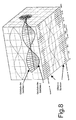
- a sinusoidal curve like in Fig.5 is shown.
- the period of the sinusoid corresponds an orbit revolution, wherein the relative phase offset between the satellites one-third of an orbit in each case (i.e., 120 degrees).
- the one used for the presentation Approximation is sufficient, since the satellite orbits in remote sensing has an inclination close to 90 degrees, and because the Across Track Offset is small (about a few hundred meters to a few 10 km, depending on the SAR system design). Even with still Larger across-track offsets remain the benefits of the new Configuration versus cartwheel configuration.
- the Across-Track Baselines are exemplary between three assumed receiving satellites of the invention Configuration shown.
- For the Across Track Interferometry is basically always the largest available standing baseline selected. From Fig.6 it can be seen that with three receiving satellites always at least 87% of the largest baseline available as a maximum baseline stands. Other smaller baselines can be used for example Support of the unwrapping method can be used.
- Figure 7 is the basic geometry of a configuration shown with two receiving satellites SAT1 and SAT2, in which the satellite orbits as in Figure 4 in different Layers lie, i. slightly different inclinations and / or different Ascending Nodes. This results in a horizontal Across-Track Baseline, their length depends on the orbit position periodically fluctuates. This is shown in FIG. 7 by a projection onto the xy plane illustrated.
- the Length of the effective baseline i. the distance between the Satellites following an orthogonal projection along the viewing direction of the radar results.
- the effective Across-Track Baselines drawn for a viewing angle of either -45 ° (bottom left) or + 45 ° (bottom right).
- the length of the effective baseline varies sinusoidal as a function of the orbital position.
- a send and receive configuration is selected, the depending on the orbital position to the left or to the right Radarsat-II - a new satellite, to be launched in 2003 - in conjunction with suitably rotating passive microsatellites) Get an effective across-track baseline, which is always at least 71% of their maximum length.
- This is an interferometric Illustration of the entire earth's surface with only two reception satellites possible. Is also taken into account that the northern and southern hemispheres of the earth orbit be shown twice, but in principle would suffice to represent these only once, so suffice a configuration with only one line of sight (either left or right) for a complete picture of the earth's surface.
- a global cover of the earth with sufficient baseline is also in other configurations with two receiving satellites possible with an angle of view on only one side (e.g. a purely vertical or a purely horizontal offset). Indeed In this case, the possibility is waived, one and the same point from two opposite directions, i. with two angles, to record. This is especially true at large terrain upgrades of interest.
- Other satellite configurations with a combination of horizontal and vertical across-track offsets are possible, for example for super-resolution and / or tomography.
- An advantage of one such a combination is that the ratio of baselines can be kept constant for all orbit positions.
- Two to three satellites are sufficient for superresolution if the terrain model (DEM) of the overflown area already known. If the DEM is not yet known, Two pendulum configurations can be combined with each other be, with the across-track displacement for the pendulum to DEM generation is about one third of the critical baseline, while the across-track offsets for superresolution comparable to the critical baseline.
- DEM terrain model
Landscapes
- Engineering & Computer Science (AREA)
- Remote Sensing (AREA)
- Radar, Positioning & Navigation (AREA)
- Physics & Mathematics (AREA)
- General Physics & Mathematics (AREA)
- Aviation & Aerospace Engineering (AREA)
- Astronomy & Astrophysics (AREA)
- Computer Networks & Wireless Communication (AREA)
- Electromagnetism (AREA)
- Combustion & Propulsion (AREA)
- Chemical & Material Sciences (AREA)
- Position Fixing By Use Of Radio Waves (AREA)
- Radar Systems Or Details Thereof (AREA)
- Radio Relay Systems (AREA)
- Geophysics And Detection Of Objects (AREA)
- Variable-Direction Aerials And Aerial Arrays (AREA)
Claims (3)
- Configuration de satellite pour un système radar à ouverture synthétique pour imagerie par interférométrie et/ou tomographie de la surface de la Terre en utilisant un émetteur embarqué et plusieurs satellites récepteurs transportant respectivement un récepteur, qui se déplacent respectivement sur une orbite avec une déviation horizontale de trajectoire transversale variable dans le trajet orbital et dont l'un d'entre eux peut également transporter l'émetteur, moyennant quoi, en supplément de la déviation horizontale de trajectoire transversale (Across-Track), une distance longitudinale (Along-Track) horizontale entre les différents satellites récepteurs est en outre réglée, qui est constante indépendamment de leurs positions orbitales, caractérisée en ce qu'il est prévu au moins trois satellites récepteurs, qui se déplacent à vitesse égale sur des orbites circulaires différentes, lesquelles se situent à des plans différents, c'est-à-dire ont des inclinaisons différentes et dont les noeuds ascendants, c'est-à-dire les points de croisement entre le plan équatorial et l'orbite satellitaire respective, sont distincts, de sorte que les maxima de déviation horizontale de trajectoire transversale entre respectivement deux satellites récepteurs sont décalés les uns par rapport aux autres, et que des Baselines (intertraces orbitales) variant périodiquement en longueur se produisent dans le trajet orbital entre les satellites récepteurs, parmi lesquelles la Baseline (intertrace orbitale) la plus longue à disposition est choisie pour l'exécution de l'interférométrie en route transversale.
- Configuration de satellite selon la revendication 1, caractérisée en ce que trois satellites récepteurs sont prévus dans trois orbites circulaires, qui se situent à des plans différents , c'est-à-dire ont des inclinaisons différentes, en ce que les noeuds ascendants des trois satellites récepteurs sont distincts, de sorte que les maxima de déviation horizontale de trajectoire transversale sont décalés d'un tiers du trajet orbital entre respectivement deux des trois satellites récepteurs et que des Baselines (intertraces orbitales) variant périodiquement en longueur dans un trajet orbital se produisent entre les trois satellites récepteurs, parmi lesquels la Baseline (intertrace orbitale) la plus longue à disposition est toujours choisie pour l'exécution de l'interférométrie en route transversale.
- Configuration de satellite pour un système radar à ouverture synthétique pour imagerie par interférométrie et/ou tomographie de la surface de la Terre en utilisant un émetteur embarqué et plusieurs satellites récepteurs transportant respectivement un récepteur, lesquels se déplacent respectivement sur une orbite avec une déviation horizontale de trajectoire transversale variable dans le trajet orbital et dont l'un d'entre eux peut également transporter l'émetteur, caractérisée en ce qu'il est prévu seulement deux satellites récepteurs, dont les orbites sont elliptiques et se situent à des plans différents, c'est-à-dire ont des inclinaisons, et dont les noeuds ascendants, c'est-à-dire les points de croisement entre le plan équatorial et l'orbite satellitaire respective sont distincts, en ce que les deux satellites récepteurs dans les deux orbites elliptiques, dont les apogées sont donnés dans des directions différentes, présentent à la fois une déviation horizontale et une déviation verticale de trajectoire transversale, de sorte que chaque point de la surface de la Terre soit représenté à partir de deux directions de visée opposées avec une Baseline (intertrace orbitale) de route transversale effective suffisante.
Applications Claiming Priority (2)
| Application Number | Priority Date | Filing Date | Title |
|---|---|---|---|
| DE10132723A DE10132723B4 (de) | 2001-07-05 | 2001-07-05 | Satellitenkonfiguration zur interferometrischen und/oder tomografischen Abbildung der Erdoberfläche mittels Radar mit synthetischer Apertur (SAR) |
| DE10132723 | 2001-07-05 |
Publications (3)
| Publication Number | Publication Date |
|---|---|
| EP1273518A2 EP1273518A2 (fr) | 2003-01-08 |
| EP1273518A3 EP1273518A3 (fr) | 2003-03-05 |
| EP1273518B1 true EP1273518B1 (fr) | 2004-11-24 |
Family
ID=7690791
Family Applications (1)
| Application Number | Title | Priority Date | Filing Date |
|---|---|---|---|
| EP02013852A Expired - Lifetime EP1273518B1 (fr) | 2001-07-05 | 2002-06-22 | Configuration de satellites d'imagerie interférométrique et/ou tomographique de la surface terrestre avec radar d'aperture synthétique |
Country Status (4)
| Country | Link |
|---|---|
| US (1) | US6677884B2 (fr) |
| EP (1) | EP1273518B1 (fr) |
| AT (1) | ATE283195T1 (fr) |
| DE (2) | DE10132723B4 (fr) |
Families Citing this family (14)
| Publication number | Priority date | Publication date | Assignee | Title |
|---|---|---|---|---|
| US7689358B2 (en) * | 2006-04-25 | 2010-03-30 | Northrop Grumman Corporation | Delta-V-free satellite cloud cluster flying |
| US7511655B2 (en) * | 2006-09-25 | 2009-03-31 | The United States Of America As Represented By The Secretary Of The Navy | Method and apparatus for 3-D sub-voxel position imaging with synthetic aperture radar |
| FR2920615B1 (fr) * | 2007-08-31 | 2011-01-28 | Centre Nat Etd Spatiales | Instrument d'acquisition et de distribution d'images d'observation terrestre a haute resolution spatiale et temporelle |
| US9857475B2 (en) | 2008-09-09 | 2018-01-02 | Geooptics, Inc. | Cellular interferometer for continuous earth remote observation (CICERO) |
| RU2447457C2 (ru) * | 2009-09-07 | 2012-04-10 | Учреждение Российской академии наук Институт океанологии им. П.П. Ширшова РАН | Радиолокационный способ оперативной диагностики океанских явлений из космоса |
| ITTO20110526A1 (it) * | 2011-06-15 | 2012-12-16 | Thales Alenia Space Italia S P A C On Unico Socio | Acquisizione di immagini sar per calcolare una quota o un modello digitale di elevazione tramite elaborazioni interferometriche |
| CN102621994B (zh) * | 2012-04-05 | 2014-04-02 | 北京理工大学 | 一种地球同步轨道合成孔径雷达覆盖中国全境的控制方法 |
| ITTO20121117A1 (it) * | 2012-12-20 | 2014-06-21 | Thales Alenia Space Italia S P A C On Unico Socio | Innovativo design orbitale per missioni spaziali di osservazione della terra |
| US10718869B2 (en) | 2018-03-05 | 2020-07-21 | Geooptics, Inc. | Symmetrical multistatic radar constellation for earth observation |
| CN109031291B (zh) * | 2018-06-26 | 2020-08-04 | 中国科学院遥感与数字地球研究所 | 评估sar信号探测次地表目标能力的方法 |
| RU2763947C2 (ru) * | 2018-07-30 | 2022-01-11 | Федеральное государственное бюджетное учреждение науки Институт океанологии им. П.П. Ширшова РАН | Способ идентификации подводного гидродинамического источника (гди) по квазизеркальному радиолокационному изображению морской поверхности |
| EP4020013B1 (fr) * | 2019-08-23 | 2024-08-14 | Spacety Co., Ltd (Changsha) | Système de détection à distance basé sur la formation de satellites, et système de constellation |
| CN110456350B (zh) * | 2019-08-23 | 2021-06-22 | 长沙天仪空间科技研究院有限公司 | 一种星载sar星座系统 |
| CN113688560B (zh) * | 2021-07-13 | 2023-09-29 | 中南大学 | 面向多星单侦察目标的轨道机动优化方法 |
Family Cites Families (24)
| Publication number | Priority date | Publication date | Assignee | Title |
|---|---|---|---|---|
| US3243706A (en) * | 1961-10-05 | 1966-03-29 | Grisham William Howard | Satellite net configured for uninterrupted global coverage and dynamically balanced tracking |
| US4602257A (en) * | 1984-06-15 | 1986-07-22 | Grisham William H | Method of satellite operation using synthetic aperture radar addition holography for imaging |
| US4854527A (en) * | 1985-07-19 | 1989-08-08 | Draim John E | Tetrahedral multi-satellite continuous-coverage constellation |
| US4809935A (en) * | 1985-07-31 | 1989-03-07 | Analytic Services, Inc. | Satellite continuous coverage constellations |
| US4727373A (en) * | 1986-03-31 | 1988-02-23 | Loral Corporation | Method and system for orbiting stereo imaging radar |
| JPH05288843A (ja) * | 1992-04-14 | 1993-11-05 | Nec Corp | 干渉型合成開口レーダ装置 |
| US6102335A (en) * | 1992-06-02 | 2000-08-15 | Mobile Communications Holdings, Inc. | Elliptical orbit satellite, system, and deployment with controllable coverage characteristics |
| US5931417A (en) * | 1992-06-02 | 1999-08-03 | Mobile Communications Holdings, Inc. | Non-geostationary orbit satellite constellation for continuous coverage of northern latitudes above 25° and its extension to global coverage tailored to the distribution of populated land masses on earth |
| FR2749996B1 (fr) * | 1996-06-18 | 1998-07-24 | Alcatel Espace | Constellation de satellites non geostationnaires a couverture permanente |
| US5923278A (en) * | 1996-07-11 | 1999-07-13 | Science Applications International Corporation | Global phase unwrapping of interferograms |
| US6011505A (en) * | 1996-07-11 | 2000-01-04 | Science Applications International Corporation | Terrain elevation measurement by interferometric synthetic aperture radar (IFSAR) |
| US5890679A (en) * | 1996-09-26 | 1999-04-06 | Loral Aerospace Corp. | Medium earth orbit communication satellite system |
| US5911389A (en) * | 1996-12-20 | 1999-06-15 | Lockheed Martin Corp. | Wave based satellite constellation |
| US6050525A (en) * | 1997-04-29 | 2000-04-18 | Lockheed Martin Corporation | Asymmetric open rosette constellations |
| US6007027A (en) * | 1997-11-14 | 1999-12-28 | Motorola, Inc. | Method and apparatus for early service using phased satellite depolyment |
| FR2778747B1 (fr) | 1998-05-13 | 2000-08-04 | Centre Nat Etd Spatiales | Dispositif d'interferometrie radar utilisant des satellites |
| FR2787185B1 (fr) | 1998-12-15 | 2001-03-02 | Centre Nat Etd Spatiales | Procede et systeme satellitaire pour etablir par interferometrie radar un modele numerique de terrain de tout ou partie de la terre |
| US6267329B1 (en) * | 1999-01-14 | 2001-07-31 | Loral Aerospace Corp. | Medium earth orbit communications satellite system |
| US6275677B1 (en) * | 1999-03-03 | 2001-08-14 | Orbcomm Global, L.P. | Method and apparatus for managing a constellation of satellites in low earth orbit |
| DE19929143A1 (de) * | 1999-06-26 | 2000-12-28 | Deutsch Zentr Luft & Raumfahrt | Hochauflösendes Synthetik-Apertur-Radarsystem |
| AU1326901A (en) * | 1999-08-16 | 2001-03-13 | Mobile Communications Holdings, Inc. | Constellation of elliptical orbit satellites with line of apsides lying in or near the equatorial plane |
| DE19938592C2 (de) * | 1999-08-18 | 2003-02-27 | Deutsch Zentr Luft & Raumfahrt | Flugzeug- oder weltraumflugkörpergetragenes Radarsystem mit synthetischer Antennenapertur |
| US6453220B1 (en) * | 2000-01-31 | 2002-09-17 | Space Systems/Loral, Inc. | Low earth orbit satellite constellation stationkeeping algorithm with absolute altitude control |
| EP1297358A4 (fr) * | 2000-05-04 | 2004-10-06 | Rosae Inc | Dispositif et procede pour holographie a accumulation progressive et a rayonnement par interferometrie en hyperfrequences |
-
2001
- 2001-07-05 DE DE10132723A patent/DE10132723B4/de not_active Expired - Fee Related
-
2002
- 2002-06-22 DE DE50201601T patent/DE50201601D1/de not_active Expired - Lifetime
- 2002-06-22 AT AT02013852T patent/ATE283195T1/de not_active IP Right Cessation
- 2002-06-22 EP EP02013852A patent/EP1273518B1/fr not_active Expired - Lifetime
- 2002-07-01 US US10/186,829 patent/US6677884B2/en not_active Expired - Lifetime
Also Published As
| Publication number | Publication date |
|---|---|
| US6677884B2 (en) | 2004-01-13 |
| EP1273518A3 (fr) | 2003-03-05 |
| ATE283195T1 (de) | 2004-12-15 |
| DE50201601D1 (de) | 2004-12-30 |
| US20030006927A1 (en) | 2003-01-09 |
| EP1273518A2 (fr) | 2003-01-08 |
| DE10132723A1 (de) | 2003-01-23 |
| DE10132723B4 (de) | 2006-03-30 |
Similar Documents
| Publication | Publication Date | Title |
|---|---|---|
| EP1273518B1 (fr) | Configuration de satellites d'imagerie interférométrique et/ou tomographique de la surface terrestre avec radar d'aperture synthétique | |
| DE69933099T2 (de) | Verfahren und System zur Bestimmung der Position eines Kommunikationssatelliten mittels Zweiweg-Entfernungsbestimmung | |
| DE69021354T2 (de) | System zur Detektion eines Hindernisses. | |
| DE102009030672B3 (de) | Verfahren zur Bestimmung der geographischen Koordinaten von Bildpunkten in SAR Bildern | |
| DE3922428C2 (fr) | ||
| DE69421590T2 (de) | SAR/GPS inertielles Verfahren zur Distanzmessung | |
| DE3712065C1 (de) | Verfahren zur topografischen Kartierung | |
| DE2628379C2 (de) | Seitensicht-Impuls-Doppler-Radargerät | |
| EP0406879B1 (fr) | Méthode d'extraction d'erreurs de mouvement d'un porteur transportant un système radar d'imagerie cohérent à partir de données radar brutes et dispositif pour la mise en oeuvre de ce procédé | |
| DE2013906A1 (de) | Navigationsverfahren für ein Fahrzeug sowie System zur Durchführung dieses Verfahrens | |
| DE19737592A1 (de) | Lagebestimmungssystem für künstliche Satelliten | |
| DE69026583T2 (de) | Radar mit synthetischer Apertur und Strahlkeulenschärfungsfähigkeit in der Richtung der Fahrt | |
| DE2205343C3 (de) | Flugzeug-Impulsradarsystem zur Ermöglichung eines unabhängigen Landens | |
| DE69302207T2 (de) | Verfahren und Vorrichtung zum Bestimmen der relativen Lage und Trajektorie von zwei Raumfahrzeugen | |
| DE69725547T2 (de) | Verfahren und vorrichtung für geodäsie und/oder bilderzeugung mittels bearbeitung von satellitensignalen | |
| DE1756619A1 (de) | Vorrichtung zur Navigation von Fahrzeugen | |
| DE69615621T2 (de) | Verfahren zur Steuerung einer Antennestellantrieb für umlaufenden Satellit | |
| DE102017111091A1 (de) | Satellitensystem für die Navigation und/oder die Geodäsie | |
| EP1065518A2 (fr) | Radar à aperture synthétique avec grande résolution | |
| DE60004858T2 (de) | Satellitensystem mit hochfrequenzantenne | |
| EP1515159B1 (fr) | Méthode pour réduire le centroide doppler pour des systèmes radar coherent à impulsion | |
| DE19803064C1 (de) | Optisches Aufklärungssystem | |
| DE3823814A1 (de) | Flugkoerperfuehrungssystem | |
| WO2017177246A1 (fr) | Scanner laser | |
| DE202019105270U1 (de) | System zur Herleitung von Seestatusparametern |
Legal Events
| Date | Code | Title | Description |
|---|---|---|---|
| PUAI | Public reference made under article 153(3) epc to a published international application that has entered the european phase |
Free format text: ORIGINAL CODE: 0009012 |
|
| AK | Designated contracting states |
Kind code of ref document: A2 Designated state(s): AT BE CH CY DE DK ES FI FR GB GR IE IT LI LU MC NL PT SE TR |
|
| AX | Request for extension of the european patent |
Free format text: AL;LT;LV;MK;RO;SI |
|
| PUAL | Search report despatched |
Free format text: ORIGINAL CODE: 0009013 |
|
| AK | Designated contracting states |
Kind code of ref document: A3 Designated state(s): AT BE CH CY DE DK ES FI FR GB GR IE IT LI LU MC NL PT SE TR Designated state(s): AT BE CH CY DE DK ES FI FR GB GR IE IT LI LU MC NL PT SE TR |
|
| AX | Request for extension of the european patent |
Extension state: AL LT LV MK RO SI |
|
| 17P | Request for examination filed |
Effective date: 20030818 |
|
| AKX | Designation fees paid |
Designated state(s): AT BE CH CY DE DK ES FI FR GB GR IE IT LI LU MC NL PT SE TR |
|
| 17Q | First examination report despatched |
Effective date: 20031022 |
|
| GRAP | Despatch of communication of intention to grant a patent |
Free format text: ORIGINAL CODE: EPIDOSNIGR1 |
|
| GRAS | Grant fee paid |
Free format text: ORIGINAL CODE: EPIDOSNIGR3 |
|
| GRAA | (expected) grant |
Free format text: ORIGINAL CODE: 0009210 |
|
| AK | Designated contracting states |
Kind code of ref document: B1 Designated state(s): AT BE CH CY DE DK ES FI FR GB GR IE IT LI LU MC NL PT SE TR |
|
| PG25 | Lapsed in a contracting state [announced via postgrant information from national office to epo] |
Ref country code: IT Free format text: LAPSE BECAUSE OF FAILURE TO SUBMIT A TRANSLATION OF THE DESCRIPTION OR TO PAY THE FEE WITHIN THE PRESCRIBED TIME-LIMIT;WARNING: LAPSES OF ITALIAN PATENTS WITH EFFECTIVE DATE BEFORE 2007 MAY HAVE OCCURRED AT ANY TIME BEFORE 2007. THE CORRECT EFFECTIVE DATE MAY BE DIFFERENT FROM THE ONE RECORDED. Effective date: 20041124 Ref country code: IE Free format text: LAPSE BECAUSE OF FAILURE TO SUBMIT A TRANSLATION OF THE DESCRIPTION OR TO PAY THE FEE WITHIN THE PRESCRIBED TIME-LIMIT Effective date: 20041124 Ref country code: FI Free format text: LAPSE BECAUSE OF FAILURE TO SUBMIT A TRANSLATION OF THE DESCRIPTION OR TO PAY THE FEE WITHIN THE PRESCRIBED TIME-LIMIT Effective date: 20041124 Ref country code: TR Free format text: LAPSE BECAUSE OF FAILURE TO SUBMIT A TRANSLATION OF THE DESCRIPTION OR TO PAY THE FEE WITHIN THE PRESCRIBED TIME-LIMIT Effective date: 20041124 |
|
| REG | Reference to a national code |
Ref country code: GB Ref legal event code: FG4D Free format text: NOT ENGLISH |
|
| REG | Reference to a national code |
Ref country code: CH Ref legal event code: EP |
|
| REF | Corresponds to: |
Ref document number: 50201601 Country of ref document: DE Date of ref document: 20041230 Kind code of ref document: P |
|
| REG | Reference to a national code |
Ref country code: IE Ref legal event code: FG4D Free format text: GERMAN |
|
| GBT | Gb: translation of ep patent filed (gb section 77(6)(a)/1977) |
Effective date: 20050115 |
|
| PG25 | Lapsed in a contracting state [announced via postgrant information from national office to epo] |
Ref country code: GR Free format text: LAPSE BECAUSE OF FAILURE TO SUBMIT A TRANSLATION OF THE DESCRIPTION OR TO PAY THE FEE WITHIN THE PRESCRIBED TIME-LIMIT Effective date: 20050224 Ref country code: SE Free format text: LAPSE BECAUSE OF FAILURE TO SUBMIT A TRANSLATION OF THE DESCRIPTION OR TO PAY THE FEE WITHIN THE PRESCRIBED TIME-LIMIT Effective date: 20050224 Ref country code: DK Free format text: LAPSE BECAUSE OF FAILURE TO SUBMIT A TRANSLATION OF THE DESCRIPTION OR TO PAY THE FEE WITHIN THE PRESCRIBED TIME-LIMIT Effective date: 20050224 |
|
| PG25 | Lapsed in a contracting state [announced via postgrant information from national office to epo] |
Ref country code: ES Free format text: LAPSE BECAUSE OF FAILURE TO SUBMIT A TRANSLATION OF THE DESCRIPTION OR TO PAY THE FEE WITHIN THE PRESCRIBED TIME-LIMIT Effective date: 20050306 |
|
| PG25 | Lapsed in a contracting state [announced via postgrant information from national office to epo] |
Ref country code: CY Free format text: LAPSE BECAUSE OF FAILURE TO SUBMIT A TRANSLATION OF THE DESCRIPTION OR TO PAY THE FEE WITHIN THE PRESCRIBED TIME-LIMIT Effective date: 20050622 Ref country code: AT Free format text: LAPSE BECAUSE OF NON-PAYMENT OF DUE FEES Effective date: 20050622 Ref country code: LU Free format text: LAPSE BECAUSE OF NON-PAYMENT OF DUE FEES Effective date: 20050622 |
|
| REG | Reference to a national code |
Ref country code: IE Ref legal event code: FD4D |
|
| PG25 | Lapsed in a contracting state [announced via postgrant information from national office to epo] |
Ref country code: BE Free format text: LAPSE BECAUSE OF NON-PAYMENT OF DUE FEES Effective date: 20050630 Ref country code: MC Free format text: LAPSE BECAUSE OF NON-PAYMENT OF DUE FEES Effective date: 20050630 |
|
| PLBE | No opposition filed within time limit |
Free format text: ORIGINAL CODE: 0009261 |
|
| STAA | Information on the status of an ep patent application or granted ep patent |
Free format text: STATUS: NO OPPOSITION FILED WITHIN TIME LIMIT |
|
| ET | Fr: translation filed | ||
| 26N | No opposition filed |
Effective date: 20050825 |
|
| PG25 | Lapsed in a contracting state [announced via postgrant information from national office to epo] |
Ref country code: CH Free format text: LAPSE BECAUSE OF NON-PAYMENT OF DUE FEES Effective date: 20060630 Ref country code: LI Free format text: LAPSE BECAUSE OF NON-PAYMENT OF DUE FEES Effective date: 20060630 |
|
| REG | Reference to a national code |
Ref country code: CH Ref legal event code: PL |
|
| BERE | Be: lapsed |
Owner name: DEUTSCHES *ZENTRUM FUR LUFT- UND RAUMFAHRT E.V. Effective date: 20050630 |
|
| PG25 | Lapsed in a contracting state [announced via postgrant information from national office to epo] |
Ref country code: PT Free format text: LAPSE BECAUSE OF NON-PAYMENT OF DUE FEES Effective date: 20050424 |
|
| PGFP | Annual fee paid to national office [announced via postgrant information from national office to epo] |
Ref country code: NL Payment date: 20110615 Year of fee payment: 10 |
|
| REG | Reference to a national code |
Ref country code: NL Ref legal event code: V1 Effective date: 20130101 |
|
| PG25 | Lapsed in a contracting state [announced via postgrant information from national office to epo] |
Ref country code: NL Free format text: LAPSE BECAUSE OF NON-PAYMENT OF DUE FEES Effective date: 20130101 |
|
| REG | Reference to a national code |
Ref country code: FR Ref legal event code: PLFP Year of fee payment: 14 |
|
| REG | Reference to a national code |
Ref country code: FR Ref legal event code: PLFP Year of fee payment: 15 |
|
| REG | Reference to a national code |
Ref country code: FR Ref legal event code: PLFP Year of fee payment: 16 |
|
| REG | Reference to a national code |
Ref country code: FR Ref legal event code: PLFP Year of fee payment: 17 |
|
| PGFP | Annual fee paid to national office [announced via postgrant information from national office to epo] |
Ref country code: FR Payment date: 20210520 Year of fee payment: 20 Ref country code: DE Payment date: 20210512 Year of fee payment: 20 |
|
| PGFP | Annual fee paid to national office [announced via postgrant information from national office to epo] |
Ref country code: GB Payment date: 20210528 Year of fee payment: 20 |
|
| REG | Reference to a national code |
Ref country code: DE Ref legal event code: R071 Ref document number: 50201601 Country of ref document: DE |
|
| REG | Reference to a national code |
Ref country code: GB Ref legal event code: PE20 Expiry date: 20220621 |
|
| PG25 | Lapsed in a contracting state [announced via postgrant information from national office to epo] |
Ref country code: GB Free format text: LAPSE BECAUSE OF EXPIRATION OF PROTECTION Effective date: 20220621 |