EP1273483A2 - Stossfängerabstützung für verbesserten Fussgängerschutz bei Kraftfahrzeugen - Google Patents
Stossfängerabstützung für verbesserten Fussgängerschutz bei Kraftfahrzeugen Download PDFInfo
- Publication number
- EP1273483A2 EP1273483A2 EP02013688A EP02013688A EP1273483A2 EP 1273483 A2 EP1273483 A2 EP 1273483A2 EP 02013688 A EP02013688 A EP 02013688A EP 02013688 A EP02013688 A EP 02013688A EP 1273483 A2 EP1273483 A2 EP 1273483A2
- Authority
- EP
- European Patent Office
- Prior art keywords
- support
- spoiler
- bumper
- vehicle
- bumper system
- Prior art date
- Legal status (The legal status is an assumption and is not a legal conclusion. Google has not performed a legal analysis and makes no representation as to the accuracy of the status listed.)
- Granted
Links
Images
Classifications
-
- B—PERFORMING OPERATIONS; TRANSPORTING
- B60—VEHICLES IN GENERAL
- B60R—VEHICLES, VEHICLE FITTINGS, OR VEHICLE PARTS, NOT OTHERWISE PROVIDED FOR
- B60R19/00—Wheel guards; Radiator guards, e.g. grilles; Obstruction removers; Fittings damping bouncing force in collisions
- B60R19/02—Bumpers, i.e. impact receiving or absorbing members for protecting vehicles or fending off blows from other vehicles or objects
- B60R19/04—Bumpers, i.e. impact receiving or absorbing members for protecting vehicles or fending off blows from other vehicles or objects formed from more than one section in a side-by-side arrangement
- B60R19/12—Bumpers, i.e. impact receiving or absorbing members for protecting vehicles or fending off blows from other vehicles or objects formed from more than one section in a side-by-side arrangement vertically spaced
-
- B—PERFORMING OPERATIONS; TRANSPORTING
- B60—VEHICLES IN GENERAL
- B60R—VEHICLES, VEHICLE FITTINGS, OR VEHICLE PARTS, NOT OTHERWISE PROVIDED FOR
- B60R19/00—Wheel guards; Radiator guards, e.g. grilles; Obstruction removers; Fittings damping bouncing force in collisions
- B60R19/02—Bumpers, i.e. impact receiving or absorbing members for protecting vehicles or fending off blows from other vehicles or objects
- B60R19/24—Arrangements for mounting bumpers on vehicles
- B60R19/26—Arrangements for mounting bumpers on vehicles comprising yieldable mounting means
- B60R19/36—Combinations of yieldable mounting means of different types
-
- B—PERFORMING OPERATIONS; TRANSPORTING
- B60—VEHICLES IN GENERAL
- B60R—VEHICLES, VEHICLE FITTINGS, OR VEHICLE PARTS, NOT OTHERWISE PROVIDED FOR
- B60R19/00—Wheel guards; Radiator guards, e.g. grilles; Obstruction removers; Fittings damping bouncing force in collisions
- B60R19/02—Bumpers, i.e. impact receiving or absorbing members for protecting vehicles or fending off blows from other vehicles or objects
- B60R19/24—Arrangements for mounting bumpers on vehicles
- B60R19/26—Arrangements for mounting bumpers on vehicles comprising yieldable mounting means
- B60R19/34—Arrangements for mounting bumpers on vehicles comprising yieldable mounting means destroyed upon impact, e.g. one-shot type
-
- B—PERFORMING OPERATIONS; TRANSPORTING
- B60—VEHICLES IN GENERAL
- B60R—VEHICLES, VEHICLE FITTINGS, OR VEHICLE PARTS, NOT OTHERWISE PROVIDED FOR
- B60R19/00—Wheel guards; Radiator guards, e.g. grilles; Obstruction removers; Fittings damping bouncing force in collisions
- B60R19/02—Bumpers, i.e. impact receiving or absorbing members for protecting vehicles or fending off blows from other vehicles or objects
- B60R19/18—Bumpers, i.e. impact receiving or absorbing members for protecting vehicles or fending off blows from other vehicles or objects characterised by the cross-section; Means within the bumper to absorb impact
- B60R2019/1886—Bumper fascias and fastening means therefor
-
- B—PERFORMING OPERATIONS; TRANSPORTING
- B60—VEHICLES IN GENERAL
- B60R—VEHICLES, VEHICLE FITTINGS, OR VEHICLE PARTS, NOT OTHERWISE PROVIDED FOR
- B60R21/00—Arrangements or fittings on vehicles for protecting or preventing injuries to occupants or pedestrians in case of accidents or other traffic risks
- B60R21/34—Protecting non-occupants of a vehicle, e.g. pedestrians
Definitions
- the invention relates to a bumper system for a motor vehicle with an energy-absorbing Structure and one with the bumper integrally formed or on this attached spoiler.
- EP 1 072 476 A2 is a bumper support for motor vehicles with an energy absorbing structure and one integral with the bumper trained or attached to this spoiler known, the spoiler by a vehicle-mounted support in its deflection in the vehicle longitudinal direction is limited and the support with radial distance behind the spoiler is arranged.
- the invention is based on the object, a bumper system for motor vehicles in such a way that the pedestrian protection is improved and at high forces the front end is protected.
- this object is achieved in that in the support Deformation and a breaking point are integrated.
- the deformation area in the support increases this energy up. This goes so far as well as the deformation area completely is compressed. If the impact energy is even greater, it breaks Breaking point and thus the support from. This protects the frontend.
- the support is attached to the front end or integrated in the front end.
- the deformation region is a bellows.
- the prerequisite is that the deformation area is an energy-absorbing Structure has.
- the breaking point is advantageously a tearing screw, z. B. which is attached to the support at the front end.
- the spoiler-facing end of the support is congruent designed to the shape of the spoiler, so that the largest possible area is available for support. It's enough, if the end the support is adapted to the shape of the spoiler.
- the support extends integrally almost over the entire width of the vehicle, so that the spoiler is supported everywhere.
- the support according to the invention made of sheet metal, plastic or a hybrid.
- the energy absorbing structure is a Foam.
- the bumper system according to the invention is particularly suitable for passenger cars.
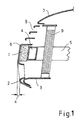
- Fig. 1 shows in a section a front end of a motor vehicle or passenger car According to the state of the art.
- a Cross member 4 is arranged, in front of which there is an energy absorbing structure 1, which consists of foam.
- the outer skin 6 of the bumper surrounds the energy absorbing structure 1 and also at the same time forms the below Spoiler 2.
- the hood 7, the ventilation slots. 8 and the radiator 9 indicated schematically.
- the spoiler 2 by a support 3 in its deflection limited in the vehicle longitudinal direction.
- vehicle longitudinal direction is the extension the side member 5 understood.
- the support 3 is at a radial distance arranged behind the spoiler.
- the dimension x indicates the deflection of the spoiler 2 until it rests against the support 3.
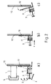
- Fig. 2a shows in a section a front end 10 of a motor vehicle or passenger car.
- an energy absorbing structure. 1 arranged, which consists of foam.
- the outer skin 6 of a bumper surrounds this energy absorbing structure 1 and also forms the same time Spoiler 2.
- the spoiler 2 is in its extension in the vehicle longitudinal direction by the support 3 limited. This support 3 is at a radial distance behind the Spoiler 2 arranged.
- a deformation region 11 is integrated according to the invention.
- the deformation area 11 is a bellows.
- the support 3 is attached to the front end 10.
- This screw 12 is formed as a predetermined breaking point.
- the described Fig. 2a shows a view at rest, d. H. before a Accident.
- Fig. 2b shows a view in case of an accident.
- the deformation area 11 is compressed more or less depending on the severity of the impact. exceeds the impact energy is the energy absorbed by the deformation region 11 can, so breaks the trained as a predetermined breaking point screw 12 at a certain predetermined energy from. As a result, the front end 10 protected.
- the maximum contraction of the deformation region 11 is with an x marked in Fig. 2b.
Abstract
Description
- Fig. 1
- einen Schnitt durch ein Kfz Frontend mit einer Abstützung des Spoilers nach dem Stand der Technik und
- Fig. 2a, b, c
- eine erfindungsgemäße Ausführungsform in drei Phasen.
Claims (6)
- Stoßfängersystem für ein Kraftfahrzeug mit einer energieabsorbierenden Struktur (1) und einem mit dem Stoßfänger einstückig ausgebildeten oder an diesem befestigten Spoiler (2), wobei der Spoiler (2) durch eine am Fahrzeug angebrachte Abstützung (3) in seiner Auslenkung in Fahrzeuglängsrichtung begrenzt ist, und die Abstützung (3) mit radialem Abstand hinter dem Spoiler (2) angeordnet ist, dadurch gekennzeichnet, dass in der Abstützung (3) ein Deformationsbereich (11) und eine Sollbruchstelle 812) integriert sind.
- Stoßfängersystem nach Anspruch 1, dadurch gekennzeichnet, dass der Deformationsbereich (11) ein Federbalg ist.
- Stoßfängersystem nach Anspruch 1 oder 2, dadurch gekennzeichnet, dass die Sollbruchstelle (12) eine abreißende Schraubverbindung ist.
- Stoßfängersystem nach einem der Ansprüche 1 bis 3, dadurch gekennzeichnet, dass die Abstützung (3) am Frontend (10) befestigt oder im Frontend (10) integriert ist.
- Stoßfängersystem nach einem der Ansprüche 1 bis 4, dadurch gekennzeichnet, dass die Abstützung (3) sich nahezu über die gesamte Breite des Fahrzeugs erstreckt.
- Stoßfängersystem nach einem der Ansprüche 1 bis 5, dadurch gekennzeichnet, dass die Abstützung (3) ein Kunststoffteil ist.
Applications Claiming Priority (4)
| Application Number | Priority Date | Filing Date | Title |
|---|---|---|---|
| DE10132704 | 2001-07-05 | ||
| DE10132704 | 2001-07-05 | ||
| DE10137911A DE10137911A1 (de) | 2001-07-05 | 2001-08-02 | Stossfängerabstützung für verbesserten Fussgängerschutz bei Kraftfahrzeugen |
| DE10137911 | 2001-08-02 |
Publications (3)
| Publication Number | Publication Date |
|---|---|
| EP1273483A2 true EP1273483A2 (de) | 2003-01-08 |
| EP1273483A3 EP1273483A3 (de) | 2003-04-09 |
| EP1273483B1 EP1273483B1 (de) | 2005-02-02 |
Family
ID=26009651
Family Applications (1)
| Application Number | Title | Priority Date | Filing Date |
|---|---|---|---|
| EP02013688A Expired - Lifetime EP1273483B1 (de) | 2001-07-05 | 2002-06-20 | Stossfängerabstützung für verbesserten Fussgängerschutz bei Kraftfahrzeugen |
Country Status (3)
| Country | Link |
|---|---|
| EP (1) | EP1273483B1 (de) |
| AT (1) | ATE288372T1 (de) |
| ES (1) | ES2237634T3 (de) |
Cited By (7)
| Publication number | Priority date | Publication date | Assignee | Title |
|---|---|---|---|---|
| EP1726490A1 (de) * | 2005-05-27 | 2006-11-29 | Honda Motor Co., Ltd | Vorderwagenaufbau eines Kraftfahrzeuges |
| FR2927865A1 (fr) * | 2008-02-27 | 2009-08-28 | Peugeot Citroen Automobiles Sa | Dispositif d'absorption de choc avec absorbeurs superieur et interieur relies par un element de liaison deformable |
| FR2936755A1 (fr) * | 2008-10-02 | 2010-04-09 | Peugeot Citroen Automobiles Sa | Poutre d'absorption de choc et vehicule automobile equipe d'une telle poutre. |
| CN101844550A (zh) * | 2010-05-10 | 2010-09-29 | 清华大学 | 具有两种吸能模式的汽车保险杠 |
| DE102015205283A1 (de) * | 2015-03-24 | 2016-09-29 | Bombardier Transportation Gmbh | Frontanordnung eines Schienenfahrzeugs sowie Verfahren zum Betreiben und Herstellen des Schienenfahrzeugs |
| WO2018115230A1 (de) * | 2016-12-22 | 2018-06-28 | Bayerische Motoren Werke Aktiengesellschaft | Stossfängeranordnung für den frontbereich eines personenkraftwagens |
| US10875480B2 (en) | 2016-12-22 | 2020-12-29 | Bayerische Motoren Werke Aktiengesellschaft | Bumper arrangement for the front region of a passenger car |
Citations (1)
| Publication number | Priority date | Publication date | Assignee | Title |
|---|---|---|---|---|
| EP1072476A2 (de) | 1999-07-26 | 2001-01-31 | Dynamit Nobel Kunststoff GmbH | Stossfängerabstützung für verbesserten Fussgängerschutz bei Kraftfahrzeugen |
Family Cites Families (4)
| Publication number | Priority date | Publication date | Assignee | Title |
|---|---|---|---|---|
| US3938841A (en) * | 1973-12-07 | 1976-02-17 | Ford Motor Company | Resilient bumper assembly |
| JPH04303046A (ja) * | 1991-03-29 | 1992-10-27 | Aisin Seiki Co Ltd | 車両用バンパ装置 |
| EP1065108B1 (de) * | 1999-06-28 | 2004-04-21 | Mazda Motor Corporation | Kraftfahrzeug- Vorderwagenaufbau |
| JP4006894B2 (ja) * | 1999-07-29 | 2007-11-14 | マツダ株式会社 | 車両の前部車体構造 |
-
2002
- 2002-06-20 ES ES02013688T patent/ES2237634T3/es not_active Expired - Lifetime
- 2002-06-20 AT AT02013688T patent/ATE288372T1/de active
- 2002-06-20 EP EP02013688A patent/EP1273483B1/de not_active Expired - Lifetime
Patent Citations (1)
| Publication number | Priority date | Publication date | Assignee | Title |
|---|---|---|---|---|
| EP1072476A2 (de) | 1999-07-26 | 2001-01-31 | Dynamit Nobel Kunststoff GmbH | Stossfängerabstützung für verbesserten Fussgängerschutz bei Kraftfahrzeugen |
Cited By (10)
| Publication number | Priority date | Publication date | Assignee | Title |
|---|---|---|---|---|
| EP1726490A1 (de) * | 2005-05-27 | 2006-11-29 | Honda Motor Co., Ltd | Vorderwagenaufbau eines Kraftfahrzeuges |
| CN100434310C (zh) * | 2005-05-27 | 2008-11-19 | 本田技研工业株式会社 | 汽车前部车体结构 |
| FR2927865A1 (fr) * | 2008-02-27 | 2009-08-28 | Peugeot Citroen Automobiles Sa | Dispositif d'absorption de choc avec absorbeurs superieur et interieur relies par un element de liaison deformable |
| EP2096002A1 (de) * | 2008-02-27 | 2009-09-02 | Peugeot Citroen Automobiles SA | Vorrichtung zur Aufpralldämpfung mit oberen und unteren Dämpfern, die über ein verformbares Element miteinander verbunden sind |
| FR2936755A1 (fr) * | 2008-10-02 | 2010-04-09 | Peugeot Citroen Automobiles Sa | Poutre d'absorption de choc et vehicule automobile equipe d'une telle poutre. |
| CN101844550A (zh) * | 2010-05-10 | 2010-09-29 | 清华大学 | 具有两种吸能模式的汽车保险杠 |
| DE102015205283A1 (de) * | 2015-03-24 | 2016-09-29 | Bombardier Transportation Gmbh | Frontanordnung eines Schienenfahrzeugs sowie Verfahren zum Betreiben und Herstellen des Schienenfahrzeugs |
| WO2018115230A1 (de) * | 2016-12-22 | 2018-06-28 | Bayerische Motoren Werke Aktiengesellschaft | Stossfängeranordnung für den frontbereich eines personenkraftwagens |
| US10875480B2 (en) | 2016-12-22 | 2020-12-29 | Bayerische Motoren Werke Aktiengesellschaft | Bumper arrangement for the front region of a passenger car |
| US11052844B2 (en) | 2016-12-22 | 2021-07-06 | Bayerische Motoren Werke Aktiengesellschaft | Bumper arrangement for the front region of a passenger car |
Also Published As
| Publication number | Publication date |
|---|---|
| ES2237634T3 (es) | 2005-08-01 |
| EP1273483A3 (de) | 2003-04-09 |
| EP1273483B1 (de) | 2005-02-02 |
| ATE288372T1 (de) | 2005-02-15 |
Similar Documents
| Publication | Publication Date | Title |
|---|---|---|
| EP1072476B1 (de) | Stossfängerabstützung für verbesserten Fussgängerschutz bei Kraftfahrzeugen | |
| DE102013016239B4 (de) | Fahrzeug | |
| DE19732301A1 (de) | Scheinwerferanordnung für ein Kraftfahrzeug | |
| DE102010023281A1 (de) | Karosseriestruktur mit einem Scheibenquerträger für ein Kraftfahrzeug mit einer Windschutzscheibe | |
| DE102015211544A1 (de) | Abstützeinrichtung für einen Vorderwagen eines Personenkraftfahrzeugs | |
| EP1273483B1 (de) | Stossfängerabstützung für verbesserten Fussgängerschutz bei Kraftfahrzeugen | |
| DE102019006731A1 (de) | Vorbaukarosseriestruktur eines Kraftfahrzeugs sowie Kraftfahrzeug | |
| DE10137911A1 (de) | Stossfängerabstützung für verbesserten Fussgängerschutz bei Kraftfahrzeugen | |
| EP2342099B1 (de) | Stossfängerquerträger | |
| EP3386808B1 (de) | Fussgängerschutzvorrichtung für ein kraftfahrzeug | |
| DE602004009770T2 (de) | Stoßfängersystem | |
| WO2016083291A1 (de) | Aufpralldämpfende bauteilanordnung für ein kraftfahrzeug | |
| DE102004061564B4 (de) | Stoßstangen-Trägerstruktur für Fahrzeuge | |
| DE10305652A1 (de) | Frontendbereich | |
| DE60132988T2 (de) | Motorhaubenvorrichtung | |
| DE102006002329B4 (de) | Vorrichtung zum Schutz von Personen bei einem Frontalaufprall auf die Fronthaube eines Kraftfahrzeuges | |
| DE102004024987B4 (de) | Front eines Kraftfahrzeugs mit verbessertem Fußgängerkollisionsschutz | |
| DE102013015679B4 (de) | Abstützanordnung für eine Stoßfängerverkleidung an einem Kraftwagenbug | |
| DE10317178B3 (de) | Kraftfahrzeug | |
| DE10311220B4 (de) | Personenkraftwagen | |
| DE10050689B4 (de) | Struktur zur Absorption von Aufprallenergie | |
| DE10031526A1 (de) | Stoßfängervorrichtung für ein Fahrzeug, insbesondere für ein Kraftfahrzeug | |
| DE10031372B4 (de) | Kotflügelanordnung für ein Kraftfahrzeug | |
| DE10355735B4 (de) | Kotflügelanordnung für ein Kraftfahrzeug | |
| DE19507988C2 (de) | Vorrichtung zur Erhöhung der Sicherheit von Personen in Fahrzeugen |
Legal Events
| Date | Code | Title | Description |
|---|---|---|---|
| PUAI | Public reference made under article 153(3) epc to a published international application that has entered the european phase |
Free format text: ORIGINAL CODE: 0009012 |
|
| AK | Designated contracting states |
Kind code of ref document: A2 Designated state(s): AT BE CH CY DE DK ES FI FR GB GR IE IT LI LU MC NL PT SE TR |
|
| AX | Request for extension of the european patent |
Free format text: AL;LT;LV;MK;RO;SI |
|
| PUAL | Search report despatched |
Free format text: ORIGINAL CODE: 0009013 |
|
| AK | Designated contracting states |
Kind code of ref document: A3 Designated state(s): AT BE CH CY DE DK ES FI FR GB GR IE IT LI LU MC NL PT SE TR Designated state(s): AT BE CH CY DE DK ES FI FR GB GR IE IT LI LU MC NL PT SE TR |
|
| AX | Request for extension of the european patent |
Extension state: AL LT LV MK RO SI |
|
| 17P | Request for examination filed |
Effective date: 20031009 |
|
| AKX | Designation fees paid |
Designated state(s): AT BE CH CY DE DK ES FI FR GB GR IE IT LI LU MC NL PT SE TR |
|
| GRAP | Despatch of communication of intention to grant a patent |
Free format text: ORIGINAL CODE: EPIDOSNIGR1 |
|
| GRAS | Grant fee paid |
Free format text: ORIGINAL CODE: EPIDOSNIGR3 |
|
| GRAA | (expected) grant |
Free format text: ORIGINAL CODE: 0009210 |
|
| AK | Designated contracting states |
Kind code of ref document: B1 Designated state(s): AT BE CH CY DE DK ES FI FR GB GR IE IT LI LU MC NL PT SE TR |
|
| PG25 | Lapsed in a contracting state [announced via postgrant information from national office to epo] |
Ref country code: TR Free format text: LAPSE BECAUSE OF FAILURE TO SUBMIT A TRANSLATION OF THE DESCRIPTION OR TO PAY THE FEE WITHIN THE PRESCRIBED TIME-LIMIT Effective date: 20050202 Ref country code: IE Free format text: LAPSE BECAUSE OF FAILURE TO SUBMIT A TRANSLATION OF THE DESCRIPTION OR TO PAY THE FEE WITHIN THE PRESCRIBED TIME-LIMIT Effective date: 20050202 Ref country code: FI Free format text: LAPSE BECAUSE OF FAILURE TO SUBMIT A TRANSLATION OF THE DESCRIPTION OR TO PAY THE FEE WITHIN THE PRESCRIBED TIME-LIMIT Effective date: 20050202 |
|
| REG | Reference to a national code |
Ref country code: GB Ref legal event code: FG4D Free format text: NOT ENGLISH |
|
| REG | Reference to a national code |
Ref country code: CH Ref legal event code: EP |
|
| REG | Reference to a national code |
Ref country code: IE Ref legal event code: FG4D Free format text: GERMAN |
|
| REF | Corresponds to: |
Ref document number: 50202159 Country of ref document: DE Date of ref document: 20050310 Kind code of ref document: P |
|
| PG25 | Lapsed in a contracting state [announced via postgrant information from national office to epo] |
Ref country code: SE Free format text: LAPSE BECAUSE OF FAILURE TO SUBMIT A TRANSLATION OF THE DESCRIPTION OR TO PAY THE FEE WITHIN THE PRESCRIBED TIME-LIMIT Effective date: 20050502 Ref country code: GR Free format text: LAPSE BECAUSE OF FAILURE TO SUBMIT A TRANSLATION OF THE DESCRIPTION OR TO PAY THE FEE WITHIN THE PRESCRIBED TIME-LIMIT Effective date: 20050502 Ref country code: DK Free format text: LAPSE BECAUSE OF FAILURE TO SUBMIT A TRANSLATION OF THE DESCRIPTION OR TO PAY THE FEE WITHIN THE PRESCRIBED TIME-LIMIT Effective date: 20050502 |
|
| GBT | Gb: translation of ep patent filed (gb section 77(6)(a)/1977) |
Effective date: 20050516 |
|
| PG25 | Lapsed in a contracting state [announced via postgrant information from national office to epo] |
Ref country code: LU Free format text: LAPSE BECAUSE OF NON-PAYMENT OF DUE FEES Effective date: 20050620 Ref country code: CY Free format text: LAPSE BECAUSE OF FAILURE TO SUBMIT A TRANSLATION OF THE DESCRIPTION OR TO PAY THE FEE WITHIN THE PRESCRIBED TIME-LIMIT Effective date: 20050620 |
|
| PG25 | Lapsed in a contracting state [announced via postgrant information from national office to epo] |
Ref country code: MC Free format text: LAPSE BECAUSE OF NON-PAYMENT OF DUE FEES Effective date: 20050630 |
|
| REG | Reference to a national code |
Ref country code: ES Ref legal event code: FG2A Ref document number: 2237634 Country of ref document: ES Kind code of ref document: T3 |
|
| REG | Reference to a national code |
Ref country code: IE Ref legal event code: FD4D |
|
| PLBE | No opposition filed within time limit |
Free format text: ORIGINAL CODE: 0009261 |
|
| STAA | Information on the status of an ep patent application or granted ep patent |
Free format text: STATUS: NO OPPOSITION FILED WITHIN TIME LIMIT |
|
| 26N | No opposition filed |
Effective date: 20051103 |
|
| ET | Fr: translation filed | ||
| PG25 | Lapsed in a contracting state [announced via postgrant information from national office to epo] |
Ref country code: CH Free format text: LAPSE BECAUSE OF NON-PAYMENT OF DUE FEES Effective date: 20060630 Ref country code: LI Free format text: LAPSE BECAUSE OF NON-PAYMENT OF DUE FEES Effective date: 20060630 |
|
| REG | Reference to a national code |
Ref country code: CH Ref legal event code: PL |
|
| PG25 | Lapsed in a contracting state [announced via postgrant information from national office to epo] |
Ref country code: PT Free format text: LAPSE BECAUSE OF NON-PAYMENT OF DUE FEES Effective date: 20050702 |
|
| REG | Reference to a national code |
Ref country code: DE Ref legal event code: R081 Ref document number: 50202159 Country of ref document: DE Owner name: FAURECIA EXTERIORS GMBH, DE Free format text: FORMER OWNER: PLASTAL GMBH, 91781 WEISSENBURG, DE Effective date: 20120329 |
|
| BECA | Be: change of holder's address |
Owner name: FAURECIA EXTERIORS G.M.B.H.NORDSEHLER STRASSE 38, Effective date: 20120507 |
|
| BECH | Be: change of holder |
Owner name: FAURECIA EXTERIORS G.M.B.H. Effective date: 20120507 |
|
| BECN | Be: change of holder's name |
Owner name: FAURECIA EXTERIORS G.M.B.H. Effective date: 20120507 |
|
| REG | Reference to a national code |
Ref country code: GB Ref legal event code: 732E Free format text: REGISTERED BETWEEN 20150521 AND 20150527 |
|
| REG | Reference to a national code |
Ref country code: FR Ref legal event code: PLFP Year of fee payment: 15 |
|
| REG | Reference to a national code |
Ref country code: FR Ref legal event code: PLFP Year of fee payment: 16 |
|
| REG | Reference to a national code |
Ref country code: FR Ref legal event code: PLFP Year of fee payment: 17 |
|
| PGFP | Annual fee paid to national office [announced via postgrant information from national office to epo] |
Ref country code: NL Payment date: 20190527 Year of fee payment: 18 |
|
| PGFP | Annual fee paid to national office [announced via postgrant information from national office to epo] |
Ref country code: DE Payment date: 20190521 Year of fee payment: 18 Ref country code: IT Payment date: 20190521 Year of fee payment: 18 |
|
| PGFP | Annual fee paid to national office [announced via postgrant information from national office to epo] |
Ref country code: BE Payment date: 20190523 Year of fee payment: 18 Ref country code: FR Payment date: 20190522 Year of fee payment: 18 |
|
| PGFP | Annual fee paid to national office [announced via postgrant information from national office to epo] |
Ref country code: AT Payment date: 20190522 Year of fee payment: 18 Ref country code: GB Payment date: 20190522 Year of fee payment: 18 Ref country code: ES Payment date: 20190701 Year of fee payment: 18 |
|
| REG | Reference to a national code |
Ref country code: DE Ref legal event code: R119 Ref document number: 50202159 Country of ref document: DE |
|
| REG | Reference to a national code |
Ref country code: NL Ref legal event code: MM Effective date: 20200701 |
|
| REG | Reference to a national code |
Ref country code: AT Ref legal event code: MM01 Ref document number: 288372 Country of ref document: AT Kind code of ref document: T Effective date: 20200620 |
|
| GBPC | Gb: european patent ceased through non-payment of renewal fee |
Effective date: 20200620 |
|
| REG | Reference to a national code |
Ref country code: BE Ref legal event code: MM Effective date: 20200630 |
|
| PG25 | Lapsed in a contracting state [announced via postgrant information from national office to epo] |
Ref country code: FR Free format text: LAPSE BECAUSE OF NON-PAYMENT OF DUE FEES Effective date: 20200630 Ref country code: GB Free format text: LAPSE BECAUSE OF NON-PAYMENT OF DUE FEES Effective date: 20200620 Ref country code: NL Free format text: LAPSE BECAUSE OF NON-PAYMENT OF DUE FEES Effective date: 20200701 |
|
| PG25 | Lapsed in a contracting state [announced via postgrant information from national office to epo] |
Ref country code: DE Free format text: LAPSE BECAUSE OF NON-PAYMENT OF DUE FEES Effective date: 20210101 Ref country code: AT Free format text: LAPSE BECAUSE OF NON-PAYMENT OF DUE FEES Effective date: 20200620 Ref country code: BE Free format text: LAPSE BECAUSE OF NON-PAYMENT OF DUE FEES Effective date: 20200630 |
|
| PG25 | Lapsed in a contracting state [announced via postgrant information from national office to epo] |
Ref country code: IT Free format text: LAPSE BECAUSE OF NON-PAYMENT OF DUE FEES Effective date: 20200620 |
|
| REG | Reference to a national code |
Ref country code: ES Ref legal event code: FD2A Effective date: 20211103 |
|
| PG25 | Lapsed in a contracting state [announced via postgrant information from national office to epo] |
Ref country code: ES Free format text: LAPSE BECAUSE OF NON-PAYMENT OF DUE FEES Effective date: 20200621 |