EP1271585A1 - Interrupteur à actionnement manuel. - Google Patents
Interrupteur à actionnement manuel. Download PDFInfo
- Publication number
- EP1271585A1 EP1271585A1 EP02291480A EP02291480A EP1271585A1 EP 1271585 A1 EP1271585 A1 EP 1271585A1 EP 02291480 A EP02291480 A EP 02291480A EP 02291480 A EP02291480 A EP 02291480A EP 1271585 A1 EP1271585 A1 EP 1271585A1
- Authority
- EP
- European Patent Office
- Prior art keywords
- housing
- lever
- cover
- actuating device
- switch according
- Prior art date
- Legal status (The legal status is an assumption and is not a legal conclusion. Google has not performed a legal analysis and makes no representation as to the accuracy of the status listed.)
- Granted
Links
- 238000011049 filling Methods 0.000 claims description 16
- 230000000295 complement effect Effects 0.000 claims description 8
- 230000000670 limiting effect Effects 0.000 claims description 4
- 239000000853 adhesive Substances 0.000 claims description 3
- 230000001070 adhesive effect Effects 0.000 claims 1
- 210000002445 nipple Anatomy 0.000 description 2
- 230000008859 change Effects 0.000 description 1
- 238000002347 injection Methods 0.000 description 1
- 239000007924 injection Substances 0.000 description 1
- 239000000463 material Substances 0.000 description 1
- 230000004048 modification Effects 0.000 description 1
- 238000012986 modification Methods 0.000 description 1
- 229920003023 plastic Polymers 0.000 description 1
- 239000004033 plastic Substances 0.000 description 1
- 238000012549 training Methods 0.000 description 1
- 230000007704 transition Effects 0.000 description 1
Images


Classifications
-
- H—ELECTRICITY
- H01—ELECTRIC ELEMENTS
- H01H—ELECTRIC SWITCHES; RELAYS; SELECTORS; EMERGENCY PROTECTIVE DEVICES
- H01H11/00—Apparatus or processes specially adapted for the manufacture of electric switches
- H01H11/0006—Apparatus or processes specially adapted for the manufacture of electric switches for converting electric switches
- H01H11/0018—Apparatus or processes specially adapted for the manufacture of electric switches for converting electric switches for allowing different operating parts
-
- H—ELECTRICITY
- H01—ELECTRIC ELEMENTS
- H01H—ELECTRIC SWITCHES; RELAYS; SELECTORS; EMERGENCY PROTECTIVE DEVICES
- H01H9/00—Details of switching devices, not covered by groups H01H1/00 - H01H7/00
- H01H9/20—Interlocking, locking, or latching mechanisms
- H01H9/28—Interlocking, locking, or latching mechanisms for locking switch parts by a key or equivalent removable member
- H01H9/281—Interlocking, locking, or latching mechanisms for locking switch parts by a key or equivalent removable member making use of a padlock
- H01H9/282—Interlocking, locking, or latching mechanisms for locking switch parts by a key or equivalent removable member making use of a padlock and a separate part mounted or mountable on the switch assembly and movable between an unlocking position and a locking position where it can be secured by the padlock
Definitions
- the present invention relates generally to switches for the control of electrical equipment.
- It relates more particularly to low disconnect switches manually operated voltage.
- a disconnector switch cuts off a supply circuit electric at a certain level of electric charge.
- a power circuit electrical can, for example, be a lighting circuit of a large area or of an industrial area, or a machine supply circuit industrial with high amperage.
- This switch disconnector is generally located in a box or a power supply cabinet, being fixed on a rail placed inside of the cabinet or cupboard.
- It can be positioned at the head of a box or cabinet or downstream of a another larger disconnect switch or circuit breaker.
- the switch actuation device can be located on the front of the housing or on a right or left lateral side thereof.
- the invention relates more particularly to a switch comprising an actuator positioned on a right or left lateral side of the housing.
- the cover of the switch actuation device can be directly attached to its case or positioned at a distance from it by being mounted on an external face of a wall of the cabinet or box in which the switch is positioned, the actuating device then being connected functionally at the switch via a reminder shaft which attacks the first switch pinion located on a right lateral side or left of the case.
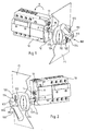
- FIGs 1 and 2 there is shown a switch, here a switch manually operated disconnector.
- this switch comprises a housing 10 containing at least one fixed contact and at minus a mobile contact (not shown).
- this housing 10 contains a plurality of fixed contacts and a plurality of corresponding movable contacts.
- this switch comprises an actuating device 100 to move each movable contact between two positions, namely a position open in which each movable contact is moved away from each fixed contact and a closed position in which each movable contact is applied to each fixed contact.
- This actuating device 100 comprises a lever 110 at the available to the user, rotatably mounted on a cover 120 positioned on one side of the housing 10 and linked to a shaft 130 which directly or indirectly attacks a first pinion 11 located on a lateral side 12 of the housing 10 to drive it in rotation in a specified direction of rotation A.
- the first pinion 11 provided on the lateral side 12 of the housing 10 is connected inside the housing to a return system for actuating all of the movable contacts secured to a mounted support (not shown) pivoting inside the housing 10.
- part internal 111 of head 110A of lever 110 forms a journal which is engaged in a central opening 121 of the cover 120 so as to allow rotation of the lever 110 on the cover 120.
- the rotary guide of the lever 110 on the cover 120 is produced by the cooperation of a rib bordering the central opening 121 of said cover 120 and a corresponding groove provided around the pin 111.
- controller 110 and the cover 120 have sliding supports 112, 122 complementary cooperating between them and comprising means for limiting the stroke of the lever 110 by two extreme positions, namely a position 0 corresponding to said open position of each movable contact and a position 1 corresponding to said closed position of each movable contact.
- the lever 110 moves from position 0 to position 1 while being actuated in the direction of ascent, that is to say in position 0 the lever 110 is oriented towards bottom (see Figures 2, 3 and 4) and, in position 1, the lever 110 is oriented towards the top (see Figures 1, 5 and 6).
- the sliding support 122 provided on the cover 120 is here constituted by a curved ramp.
- the sliding support 112 complementary to said lever 110 is a also curved groove means provided in the head 110A of the lever 110.
- Each window 113 has a lateral side situated at the end of the groove means 112 and another opposite lateral side 114 which is intended to abut against one end of the curved ramp 122 so as to limit the rotation stroke of said lever 110.
- the abutment of the lateral sides 114 of the two windows 113 corresponds to the extreme positions of the lever 110, namely position 1 and the position 0.
- the switch according to the invention also comprises a device for lock 200 which appears clearly in Figures 3 to 6.
- This device lock 200 is associated with the actuating device 100 to block the lever 110 at least in position 0.
- This locking device 200 comprises a latch 210, which is in the form of an elongated plate, and which has one end internal 211 and an external end 212.
- This latch 210 is mounted movable in rotation by a pin 213 on the lever 110 so as to be able occupy two positions, namely a retracted position (see Figures 5 and 6) in which leaves the lever 110 free to rotate on the cover 120, and a extended position (see Figures 3 and 4) in which it is capable of being padlocked and in which the internal end 211 of the latch 210 is engaged in a housing 123 provided at one end of the sliding support 122 of the cover 120 for come between said sliding support 122 and that 112 of the lever 110 in order to lock the latter in its 0 position (see Figures 3 and 4).
- the housing 123 is formed by a recess provided at the end of the curved ramp 122.
- the transition from the extended position to the retracted position of the latch 210 is achieved by manual support on the external end 212 of said latch 210 by tightening handle 110B of handle 110.
- the external end 212 of the latch 210 is arranged to receive a padlock (not shown), this external end 212 disappearing in the lever 110 in the retracted position of said latch 210 and emerging outside the lever 110 in the extended position of said clicks 210 to be accessible to the user and to receive said padlock.
- this outer end 212 has an oblong orifice.
- the housing 10, the actuating device 100 and the locking device 200 of the switch shown in FIGS. 1 and 2 include arrangements allowing the positioning of the device actuator 100 and the associated locking device 200 on the right (see Figure 1) or to the left (see Figure 2) of the housing 10.
- the device actuator 100 and the associated locking device 200 are positioned at distance from the housing 10 of the switch while being fixed on a wall P1 or P2 constituting a wall of an electrical cabinet or a cabinet inside which is placed the housing 10 of the switch. In this way, the user can operate the switch without having to open the electrical cabinet or enclosure.
- the cover 120 of the actuating device 100 is directly fixed to the lateral side 12 of the housing 10, but, in this case, to be able to actuate the switch, the user must open the electrical box or cabinet inside from which he rode.
- the fixing of the cover 120 on the wall P1 or on the wall P2 is carried out here by screwing, through orifices 120B provided on a side wall 120A of the cover 120.
- any other means of fixing the cover 120 on the walls P1 and P2 such as fixing by riveting for example.
- said arrangements provided in the housing 10, the actuating device 100 and locking device 200 imply that, to switch from positioning the actuating device 100 and the device lock 200 associated to the right of the housing 10, with a positioning of these to the left of the housing 10, the housing 10 is turned upside down bottom, according to a rotation materialized by the arrow R represented in FIG. 1.
- Said arrangements comprise a rotation means 13 provided on the lateral side 12 of the housing 10 which, in one of the positions of the device actuation 100 here to the left of the housing 10 (see Figure 2), is interposed between the shaft 130 of the actuating device 100 and the first pinion 11, so that the latter is attacked indirectly by the tree 130 to be entrained in the same direction of rotation A determined.
- said first pinion 11 is always driven in the same direction of rotation A determined.
- this means of rotation is a second pinion 13, identical to the first pinion 11, freely meshing the first pinion 11, and having a direction of rotation B reversed with respect to the direction of rotation A, the shaft 130 of the device actuator 100 directly driving the first pinion 11 when it is positioned to the right of the housing 10 and attacking this first pinion 11 through the second gear 13 of the housing when positioned to the left of the latter.
- said arrangements include, on the front of the hood 120, a detachable part 124 bearing a marking indicating the position 0 and the position 1 of said lever 110, this detachable part 124 can be positioned on said cover 120 in two positions depending on the right or left positioning of the actuating device 100.
- the detachable part 124 is here a plate which includes mounting means 124A, 124B in a receiving housing 127 provided on the front on the cover 120.
- this plate 124 has an elongated shape bringing to a end marking 0 and at the other end marking 1. It is carried out by injection of a plastic material. At each of its ends, it comprises, as mounting means, latching lugs 124A, 124B intended to cooperate with latching lugs 127A, 127B complementary provided at the end of the receiving housing 127 having a complementary shape of said plate 124.
- the plate 124 carries, on its internal face turned towards the cover 120, a tongue 124C able to pass through said through opening 127C, when snap-fastening of said plate 124 on the cover 120, to emerge from the inside of the cover (see FIG. 7), this tongue 124C forming an aid for disengaging from said plate 124.
- the detachable part 124 of the cover comprising the markings 1 and 0 or a self-adhesive sheet attached to the front of the cover 120.
- latch 210 still allows to block the lever 110 at least in position 0 corresponding to the open position mobile contacts.
- another housing 123 located at the other end of the sliding support 122 of the cover 120, this other housing 123 also being intended to accommodate said internal end 211 of the latch 210 to lock the lever 110 in its corresponding extreme position.
- a recess is provided at each end of the curved ramp 122 of the cover 120 forming a housing 123 capable of to receive the internal end 211 of the latch 210.
- the user can choose to lock the lever 110 in its position 1 corresponding to the closing of the movable contacts, and in its position 0 corresponding to opening of mobile contacts.
- filling means for fill at least one of said housings 123 provided at the ends of the support sliding 122 of cover 120 so as, if the user wishes, to authorize the lock handle 110 only in one of the two extreme positions 0 and 1 of the joystick, and conventionally position 0.
- These filling means here comprise a screw 140 screwed onto the cover 120 from the rear thereof.
- the cover 120 comprises, internally, to the right of at least one of said dwellings 123, and here to the right of each housing 123, a tapped chimney 125.
- a tapped chimney 125 is shown in detail in Figure 9. This chimney tapped 125 opens onto the bottom of the corresponding housing 123.
- each screw 140 is able to be screwed into said corresponding tapped chimney 125 and to smash the bottom 126 of said housing 123 to emerge from the outside of said cover 120 by filling the corresponding housing 123.
- the screw 140 used is a long nipple screw, and its nipple-shaped end 141 makes it possible to fill the housing 123 corresponding, as shown more particularly in FIGS. 4 and 3.
- the user can also choose to lock the lever 110 in one of its two extreme positions 1 and 0, or in neither of its two positions 1 and 0. To do this, he introduces the screw 140 in the corresponding housing 123 in order to fill it.
- the lockable position is position 0, when the actuator 100 is positioned to the right of the housing 10 as shown in Figure 1, when the actuator 100 is then positioned to the left of the box, without modification by the user, the lockable position becomes position 1 due to head-up flipping upside down of the actuating device 100.
- the user in the two positioning of the actuating device 100 to the right and left of the housing 10, the user can arrange the actuating device 100 and the lock 200 associated so that it is always the housing 123 corresponding to position 1 of lever 110 which is filled to prevent the internal end 211 of the latch 210 to introduce itself there and to block the lever 100 in this position.
- said internal end 211 of the latch 210 abuts against the nipple-shaped end 141 of the screw 140 filling said corresponding housing 123.
- the user Before introducing the shaft 130 into the second pinion 13 of the housing 10 and to fix the cover 120 on the housing 10 or on the wall P2, the user detaches the cover 124 of cover 120 to turn it over and position it upside down, so that it has marking 1 in the upper part and the lower part in marking 0 identically to the plate 124 shown in Figure 1.
- the user adapts the locking device 200 so that the lockable position of the handle 110 remains the position 0. To do this, it suffices that he unscrews the screw 140 filling the housing 123 corresponding to position 1 when the actuating device 100 is positioned to the right of the housing 10, to screw it into the housing 123 corresponding to position 1 when the actuating device 100 is placed at left of the case.
- the user finds an identical use of the actuating device that it is positioned to the right or left of the housing.
- the detachable part may be fixed by screwing or any other means on the cover of the actuating device.
Landscapes
- Engineering & Computer Science (AREA)
- Manufacturing & Machinery (AREA)
- Switch Cases, Indication, And Locking (AREA)
Abstract
Description
- un boítier renfermant au moins un contact fixe et au moins un contact mobile,
- un dispositif d'actionnement pour déplacer chaque contact mobile entre deux positions, à savoir une position ouverte dans laquelle chaque contact mobile est écarté de chaque contact fixe et une position fermée dans laquelle chaque contact mobile est appliqué sur chaque contact fixe, ce dispositif d'actionnement comprenant une manette à la disposition de l'usager, montée en rotation sur un capot et liée à un arbre qui attaque un premier pignon situé sur le boítier pour l'entraíner en rotation dans un sens de rotation déterminé, la manette et le capot présentant des appuis glissants complémentaires coopérant entre eux et comprenant des moyens pour limiter la course de la manette par deux positions extrêmes, à savoir une position 0 correspondant à ladite position ouverte de chaque contact mobile et une position 1 correspondant à ladite position fermée de chaque contact mobile, et
- un dispositif de verrouillage de la manette dans sa position 0, qui comprend une clenche présentant une extrémité interne et montée mobile sur ladite manette de façon à pouvoir occuper deux positions, à savoir une position rentrée dans laquelle elle laisse la manette libre de rotation et une position sortie dans laquelle elle est apte à être cadenassée et dans laquelle son extrémité interne est engagée dans un logement prévu à une extrémité de l'appui glissant du capot pour s'interposer entre ledit appui glissant et celui de ladite manette afin de bloquer cette dernière dans sa position 0.
- sur la façade du capot une partie détachable portant un marquage indiquant la position 0 et la position 1 de ladite manette, cette partie détachable pouvant être positionnée sur ledit capot selon deux positions en fonction du positionnement à droite ou à gauche du dispositif d'actionnement,
- un moyen de rotation prévu sur ledit côté latéral du boítier qui, dans un des positionnements du dispositif d'actionnement à droite ou à gauche du boítier, s'interpose entre l'arbre et le premier pignon pour que, quel que soit le positionnement du dispositif d'actionnement par rapport au boítier, ledit premier pignon soit toujours entraíné dans le même sens de rotation déterminé, et
- un autre logement prévu à l'autre extrémité de l'appui glissant du capot et destiné à accueillir ladite extrémité interne de la clenche pour bloquer la manette dans sa positon extrême correspondante.
- il est prévu des moyens de comblement pour combler au moins un desdits logements prévus aux extrémités de l'appui glissant du capot de manière à autoriser le verrouillage de ladite manette seulement dans une de ses deux positions extrêmes 0 et 1.
- lesdits moyens de comblement comprennent au moins une vis vissée sur le capot ;
- le capot comporte, intérieurement, au droit d'au moins un desdits logements, une cheminée taraudée, et le fond dudit logement est défonçable de sorte que chaque vis est apte à être vissée dans ladite cheminée taraudée et à défoncer le fond dudit logement pour émerger du côté extérieur dudit capot en comblant ledit logement ;
- les moyens de comblement de chaque logement comprennent un téton sécable qui s'élève à l'intérieur dudit logement ;
- l'appui glissant du capot est constitué par une rampe courbe, et l'appui glissant complémentaire de ladite manette est un moyen de rainure également courbe et il est prévu, à chaque extrémité dudit moyen de rainure, une fenêtre dont un côté latéral est destiné à venir en butée contre une extrémité de ladite rampe courbe pour limiter la course de la manette ;
- ladite partie détachable est une plaque comportant des moyens de montage dans un logement de réception prévu sur le capot ;
- lesdits moyens de montage sont des moyens d'encliquetage ;
- le fond du logement de réception prévu sur le capot comprend une ouverture traversante, et ladite plaque porte, sur sa face interne tournée vers le capot, une languette apte à traverser ladite ouverture traversante, lors de l'encliquetage de ladite plaque sur le capot, pour émerger du côté intérieur du capot, cette languette formant une aide au désencliquetage de ladite plaque ;
- ladite partie détachable est une feuille autocollante rapportée sur la façade du capot ;
- ledit moyen de rotation prévu sur le boítier est un deuxième pignon engrenant librement le premier pignon, les deux pignons tournant dans des sens de rotation inversés, ledit arbre attaquant l'un desdits pignons dans un des positionnements du dispositif d'actionnement par rapport au boítier, et attaquant l'autre desdits pignons dans l'autre des positionnements du dispositif d'actionnement par rapport au boítier ;
- la clenche comprend une extrémité externe agencée pour recevoir un cadenas, cette extrémité externe s'effaçant dans la manette dans la position rentrée de ladite clenche et émergeant à l'extérieur de ladite manette dans la position sortie de ladite clenche pour être accessible à l'usager et recevoir ledit cadenas ; et
- ladite manette passe de la positon 0 à la position 1 en étant actionnée dans le sens d'une montée, la position 0 étant une position basse de la manette et la position 1 étant une position haute de la manette.
- la figure 1 est une vue schématique en perspective d'un interrupteur selon l'invention comprenant un dispositif d'actionnement monté à droite de son boítier ;
- la figure 2 est une vue en perspective schématique de l'interrupteur représenté sur la figure 1 retourné de manière à être positionné tête en bas et comportant le dispositif d'actionnement positionné à gauche du boítier ;
- la figure 3 est une vue en perspective du dispositif d'actionnement et du dispositif de verrouillage associé de l'interrupteur représenté sur la figure 2 dans lequel la manette est positionnée en position 0 ;
- la figure 4 est une vue identique à celle de la figure 3, avec la manette du dispositif d'actionnement coupée longitudinalement pour laisser apparaítre la clenche du dispositif de verrouillage en position sortie ;
- la figure 5 est une vue en perspective du dispositif d'actionnement de l'interrupteur représenté sur la figure 1, avec la manette positionnée en position 1 ;
- la figure 6 est une vue identique à celle de la figure 5, avec la manette coupée longitudinalement pour laisser apparaítre la clenche du dispositif de verrouillage en position rentrée ;
- la figure 7 est une vue de l'intérieur du dispositif d'actionnement de l'interrupteur selon l'invention ;
- la figure 8 est une vue du dispositif d'actionnement de l'interrupteur conforme à l'invention, avec la partie détachable du capot retirée de celui-ci ;
- la figure 9 est une vue de détail partiellement coupée du capot du dispositif d'actionnement de l'interrupteur selon l'invention ; et
- la figure 10 est une vue du détail X de la figure 9.
Claims (13)
- Interrupteur comprenant :caractérisé en ce que le boítier (10), le dispositif d'actionnement (100) et le dispositif de verrouillage (200) comprennent des aménagements autorisant le positionnement du dispositif d'actionnement (100) et du dispositif de verrouillage (200) associé à droite ou à gauche du boítier (10) moyennant un retournement tête en haut tête en bas de ce dernier, de telle manière que l'usager conserve le même sens d'actionnement de ladite manette (110) pour la faire passer de la positon 0 à la position 1 et inversement, lesdits aménagements comprenant :un boítier (10) renfermant au moins un contact fixe et au moins un contact mobile,un dispositif d'actionnement (100) pour déplacer chaque contact mobile entre deux positions, à savoir une position ouverte dans laquelle chaque contact mobile est écarté de chaque contact fixe et une position fermée dans laquelle chaque contact mobile est appliqué sur chaque contact fixe, ce dispositif d'actionnement (100) comprenant une manette (110) à la disposition de l'usager, montée à rotation sur un capot (120) positionné d'un côté du boítier (10) et liée à un arbre (130) qui attaque un premier pignon (11) situé sur au moins un côté latéral (12) du boítier (10) pour l'entraíner en rotation dans un sens de rotation déterminé, la manette (110) et le capot (120) présentant des appuis glissants (112, 122) complémentaires coopérant entre eux et comprenant des moyens pour limiter la course de la manette (110) par deux positions extrêmes, à savoir une position 0 correspondant à ladite position ouverte de chaque contact mobile et une position 1 correspondant à ladite position fermée de chaque contact mobile,un dispositif de verrouillage (200) de la manette dans sa position 0, qui comprend une clenche (210) présentant une extrémité interne (211) et montée mobile sur ladite manette (110) de façon à pouvoir occuper deux positions, à savoir une position rentrée dans laquelle elle laisse la manette (110) libre de rotation et une position sortie dans laquelle elle est apte à être cadenassée et dans laquelle son extrémité interne (211) est engagée dans un logement (123) prévu à une extrémité de l'appui glissant (122) du capot (120) pour s'interposer entre ledit appui glissant (122) et celui (112) de ladite manette (110) afin de bloquer cette dernière dans sa position 0,sur la façade du capot (120) une partie détachable (124) portant un marquage indiquant la position 0 et la position 1 de ladite manette (110), cette partie détachable (124) pouvant être positionnée sur ledit capot (120) selon deux positions en fonction du positionnement à droite ou à gauche du dispositif d'actionnement (100),un moyen de rotation (13) prévu sur ledit côté latéral (12) du boítier (10) qui, dans un des positionnements du dispositif d'actionnement (100) à droite ou à gauche du boítier (10), s'interpose entre l'arbre (130) et le premier pignon (11) pour que, quel que soit le positionnement du dispositif d'actionnement (100) par rapport au boítier (10), ledit premier pignon (11) soit toujours entraíné dans le même sens de rotation déterminé, etun autre logement (123) prévu à l'autre extrémité de l'appui glissant (122) du capot (120) et destiné à accueillir ladite extrémité interne (211) de la clenche (210) pour bloquer la manette (110) dans sa positon extrême correspondante.
- Interrupteur selon la revendication 1, caractérisé en ce qu'il est prévu des moyens de comblement pour combler au moins un desdits logements (123) prévus aux extrémités de l'appui glissant (122) du capot (120) de manière à autoriser le verrouillage de ladite manette (110) seulement dans une de ses deux positions extrêmes 0 et 1.
- Interrupteur selon la revendication 2, caractérisé en ce que lesdits moyens de comblement comprennent au moins une vis (140) vissée sur le capot (120).
- Interrupteur selon la revendication 3, caractérisé en ce que le capot (120) comporte, intérieurement, au droit d'au moins un desdits logements (123), une cheminée taraudée (125), et en ce que le fond (126) dudit logement (123) est défonçable de sorte que chaque vis (140) est apte à être vissée dans ladite cheminée taraudée (125) et à défoncer le fond (126) dudit logement (123) pour émerger du côté extérieur dudit capot en comblant ledit logement (123).
- Interrupteur selon la revendication 2, caractérisé en ce que les moyens de comblement de chaque logement comprennent un téton sécable qui s'élève à l'intérieur dudit logement.
- Interrupteur selon l'une des revendications 1 à 5, caractérisé en ce que l'appui glissant (122) du capot (120) est constitué par une rampe courbe, en ce que l'appui glissant (112) complémentaire de ladite manette (110) est un moyen de rainure également courbe, et en ce qu'il est prévu, à chaque extrémité dudit moyen de rainure (112), une fenêtre (113) dont un côté latéral (114) est destiné à venir en butée contre une extrémité de ladite rampe courbe (122) pour limiter la course de la manette (110).
- Interrupteur selon l'une quelconques des revendications précédentes, caractérisé en ce que ladite partie détachable (124) est une plaque comportant des moyens de montage (124A, 124B) dans un logement de réception (127) prévu sur le capot (120).
- Interrupteur selon la revendication 7, caractérisé en ce que lesdits moyens de montage (124A, 124B) sont des moyens d'encliquetage.
- Interrupteur selon l'une des revendications 7 ou 8, caractérisé en ce que le fond du logement de réception (127) prévu sur le capot (120) comprend une ouverture traversante (127C), et ladite plaque (124) porte, sur sa face interne tournée vers le capot (120), une languette (124C) apte à traverser ladite ouverture traversante (127C), lors de l'encliquetage de ladite plaque (124) sur le capot (120), pour émerger du côté intérieur du capot, cette languette (124C) formant une aide au désencliquetage de ladite plaque (124).
- interrupteur selon l'une des revendications 1 à 6, caractérisé en ce que ladite partie détachable est une feuille autocollante rapportée sur la façade du capot.
- Interrupteur selon l'une quelconque des revendications précédentes, caractérisé en ce que ledit moyen de rotation prévu sur le boítier est un deuxième pignon (13) engrenant librement le premier pignon (11), les deux pignons (11, 13) tournant dans des sens de rotation inversés, ledit arbre (130) attaquant l'un (11) desdits pignons dans un des positionnements du dispositif d'actionnement (100) par rapport au boítier (10), et attaquant l'autre (13) desdits pignons dans l'autre des positionnements du dispositif d'actionnement (100) par rapport au boítier (10).
- Interrupteur selon l'une quelconque des revendications précédentes, caractérisé en ce que la clenche (210) comprend une extrémité externe (212) agencée pour recevoir un cadenas, cette extrémité externe (212) s'effaçant dans la manette (110) dans la position rentrée de ladite clenche (210) et émergeant à l'extérieur de ladite manette (110) dans la position sortie de ladite clenche pour être accessible à l'usager et recevoir ledit cadenas.
- Interrupteur selon l'une quelconque des revendications précédentes, caractérisé en ce que ladite manette (110) passe de la positon 0 à la position 1 en étant actionnée dans le sens d'une montée, la position 0 étant une position basse de la manette (110) et la position 1 étant une position haute de la manette (110).
Applications Claiming Priority (2)
| Application Number | Priority Date | Filing Date | Title |
|---|---|---|---|
| FR0108337A FR2826502B1 (fr) | 2001-06-25 | 2001-06-25 | Interrupteur a actionnement manuel |
| FR0108337 | 2001-06-25 |
Publications (2)
| Publication Number | Publication Date |
|---|---|
| EP1271585A1 true EP1271585A1 (fr) | 2003-01-02 |
| EP1271585B1 EP1271585B1 (fr) | 2007-09-26 |
Family
ID=8864722
Family Applications (1)
| Application Number | Title | Priority Date | Filing Date |
|---|---|---|---|
| EP20020291480 Expired - Lifetime EP1271585B1 (fr) | 2001-06-25 | 2002-06-13 | Interrupteur à actionnement manuel. |
Country Status (4)
| Country | Link |
|---|---|
| EP (1) | EP1271585B1 (fr) |
| DE (1) | DE60222611D1 (fr) |
| FR (1) | FR2826502B1 (fr) |
| PL (1) | PL198702B1 (fr) |
Cited By (2)
| Publication number | Priority date | Publication date | Assignee | Title |
|---|---|---|---|---|
| EP2393092A1 (fr) * | 2010-06-04 | 2011-12-07 | Schneider Electric Industries SAS | Dispositif de commutation |
| CN118782415A (zh) * | 2024-09-11 | 2024-10-15 | 温州金宏电器有限公司 | 一种带锁定功能的隔离开关 |
Citations (3)
| Publication number | Priority date | Publication date | Assignee | Title |
|---|---|---|---|---|
| DE4300313C1 (de) * | 1993-01-08 | 1994-03-31 | Kloeckner Moeller Gmbh | Drehantrieb für kipphebelbetätigte Schaltgeräte und Verwendung hierfür |
| DE19627691A1 (de) * | 1996-07-10 | 1998-01-15 | Felten & Guilleaume Energie | Betätigungshandhabe für ein Schaltgerät |
| DE19939717A1 (de) * | 1999-08-21 | 2001-02-22 | Moeller Gmbh | Handbetätigungsvorrichtung mit Drehgriff für elektrische Schaltgeräte |
-
2001
- 2001-06-25 FR FR0108337A patent/FR2826502B1/fr not_active Expired - Lifetime
-
2002
- 2002-06-13 EP EP20020291480 patent/EP1271585B1/fr not_active Expired - Lifetime
- 2002-06-13 DE DE60222611T patent/DE60222611D1/de not_active Expired - Lifetime
- 2002-06-20 PL PL354640A patent/PL198702B1/pl unknown
Patent Citations (3)
| Publication number | Priority date | Publication date | Assignee | Title |
|---|---|---|---|---|
| DE4300313C1 (de) * | 1993-01-08 | 1994-03-31 | Kloeckner Moeller Gmbh | Drehantrieb für kipphebelbetätigte Schaltgeräte und Verwendung hierfür |
| DE19627691A1 (de) * | 1996-07-10 | 1998-01-15 | Felten & Guilleaume Energie | Betätigungshandhabe für ein Schaltgerät |
| DE19939717A1 (de) * | 1999-08-21 | 2001-02-22 | Moeller Gmbh | Handbetätigungsvorrichtung mit Drehgriff für elektrische Schaltgeräte |
Cited By (4)
| Publication number | Priority date | Publication date | Assignee | Title |
|---|---|---|---|---|
| EP2393092A1 (fr) * | 2010-06-04 | 2011-12-07 | Schneider Electric Industries SAS | Dispositif de commutation |
| CN102280295A (zh) * | 2010-06-04 | 2011-12-14 | 施耐德电器工业公司 | 开关装置 |
| CN102280295B (zh) * | 2010-06-04 | 2014-08-13 | 施耐德电器工业公司 | 开关装置 |
| CN118782415A (zh) * | 2024-09-11 | 2024-10-15 | 温州金宏电器有限公司 | 一种带锁定功能的隔离开关 |
Also Published As
| Publication number | Publication date |
|---|---|
| DE60222611D1 (de) | 2007-11-08 |
| EP1271585B1 (fr) | 2007-09-26 |
| PL354640A1 (en) | 2002-12-30 |
| FR2826502A1 (fr) | 2002-12-27 |
| PL198702B1 (pl) | 2008-07-31 |
| FR2826502B1 (fr) | 2003-09-26 |
Similar Documents
| Publication | Publication Date | Title |
|---|---|---|
| EP0809457B1 (fr) | Batteur-mixeur electrique a main | |
| EP0610143B1 (fr) | Dispositif de condamnation mécanique et électrique d'un bloc de télécommande pour disjoncteur modulaire | |
| EP2183987B1 (fr) | Coupe-cigare | |
| EP1215985B1 (fr) | Batteur-mixeur electrique a main | |
| EP3208820B1 (fr) | Système de commande rotative pour un appareil | |
| EP2131378B1 (fr) | Dispositif de commande d'un appareil de coupure électrique comportant un dispositif de signalisation de la soudure des contacts, et appareil de coupure électrique comportant un tel dispositif | |
| FR2534739A1 (fr) | Contacteur de securite | |
| FR3108137A1 (fr) | Commande d’ouverture extérieure de porte de véhicule automobile | |
| EP1020338A1 (fr) | Dispositif d'antivol comportant un interrupteur électrique pour la détection de l'introduction d'une clef | |
| EP2377139B1 (fr) | Dispositif de télécommande et disjoncteur télécommandé equipé d'un tel dispositif | |
| EP1271585B1 (fr) | Interrupteur à actionnement manuel. | |
| EP1729313A1 (fr) | Dispositif d'actionnement d'un appareil électrique interrupteur avec dispositif de verrouillage. | |
| EP4078641B1 (fr) | Mecanisme pour un commutateur electrique,ensemble electrique et commutateur electrique associes | |
| EP1111644B1 (fr) | Dispositif de sécurité pour appareils électriques | |
| EP3840154A1 (fr) | Appareillage electrique etanche | |
| FR2548978A1 (fr) | Partie de toit relevable et amovible pour vehicule automobile | |
| FR2656026A1 (fr) | Dispositif de commande electrique d'un levier pivotant maintenu libre aux deux extremites de sa course et serrure comportant ce dispositif. | |
| FR2638887A1 (fr) | Dispositif d'actionnement pour un interrupteur electrique, notamment associe a une porte ou un capot de vehicule automobile | |
| EP1376772A1 (fr) | Socle de prise de courant à obturateur d'alvéoles et gamme comprenant un tel socle | |
| EP1515352A1 (fr) | Dispositif de coupure de courant électrique à contact mobile en translation | |
| EP2442337B1 (fr) | Dispositif de contacteur clé | |
| EP0102263A1 (fr) | Serrure à commande électrique pour portière de véhicule automobile | |
| EP0987390A1 (fr) | Platine de servitude pour la commande des serrures d'un panneau ouvrant | |
| EP1187154B1 (fr) | Appareil électrique à poussoir | |
| FR2686009A1 (fr) | Batteur-mixeur electrique a main. |
Legal Events
| Date | Code | Title | Description |
|---|---|---|---|
| PUAI | Public reference made under article 153(3) epc to a published international application that has entered the european phase |
Free format text: ORIGINAL CODE: 0009012 |
|
| AK | Designated contracting states |
Kind code of ref document: A1 Designated state(s): AT BE CH CY DE DK ES FI FR GB GR IE IT LI LU MC NL PT SE TR |
|
| AX | Request for extension of the european patent |
Free format text: AL;LT;LV;MK;RO;SI |
|
| 17P | Request for examination filed |
Effective date: 20021204 |
|
| AKX | Designation fees paid |
Designated state(s): BE DE ES GB IT |
|
| RAP1 | Party data changed (applicant data changed or rights of an application transferred) |
Owner name: LEGRAND SNC Owner name: LEGRAND FRANCE |
|
| GRAP | Despatch of communication of intention to grant a patent |
Free format text: ORIGINAL CODE: EPIDOSNIGR1 |
|
| RIN1 | Information on inventor provided before grant (corrected) |
Inventor name: GRAND, PHILIPPE Inventor name: ROYER-MANOHA, OLIVIER Inventor name: MERIGUET, MARCEL Inventor name: JACQUES, STEPHANE |
|
| GRAS | Grant fee paid |
Free format text: ORIGINAL CODE: EPIDOSNIGR3 |
|
| GRAA | (expected) grant |
Free format text: ORIGINAL CODE: 0009210 |
|
| AK | Designated contracting states |
Kind code of ref document: B1 Designated state(s): BE DE ES GB IT |
|
| REG | Reference to a national code |
Ref country code: GB Ref legal event code: FG4D Free format text: NOT ENGLISH |
|
| REF | Corresponds to: |
Ref document number: 60222611 Country of ref document: DE Date of ref document: 20071108 Kind code of ref document: P |
|
| GBV | Gb: ep patent (uk) treated as always having been void in accordance with gb section 77(7)/1977 [no translation filed] | ||
| PG25 | Lapsed in a contracting state [announced via postgrant information from national office to epo] |
Ref country code: ES Free format text: LAPSE BECAUSE OF FAILURE TO SUBMIT A TRANSLATION OF THE DESCRIPTION OR TO PAY THE FEE WITHIN THE PRESCRIBED TIME-LIMIT Effective date: 20080106 |
|
| PG25 | Lapsed in a contracting state [announced via postgrant information from national office to epo] |
Ref country code: DE Free format text: LAPSE BECAUSE OF FAILURE TO SUBMIT A TRANSLATION OF THE DESCRIPTION OR TO PAY THE FEE WITHIN THE PRESCRIBED TIME-LIMIT Effective date: 20071228 |
|
| PLBE | No opposition filed within time limit |
Free format text: ORIGINAL CODE: 0009261 |
|
| STAA | Information on the status of an ep patent application or granted ep patent |
Free format text: STATUS: NO OPPOSITION FILED WITHIN TIME LIMIT |
|
| 26N | No opposition filed |
Effective date: 20080627 |
|
| PG25 | Lapsed in a contracting state [announced via postgrant information from national office to epo] |
Ref country code: GB Free format text: LAPSE BECAUSE OF FAILURE TO SUBMIT A TRANSLATION OF THE DESCRIPTION OR TO PAY THE FEE WITHIN THE PRESCRIBED TIME-LIMIT Effective date: 20070926 |
|
| BERE | Be: lapsed |
Owner name: LEGRAND FRANCE Effective date: 20080630 Owner name: LEGRAND SNC Effective date: 20080630 |
|
| PG25 | Lapsed in a contracting state [announced via postgrant information from national office to epo] |
Ref country code: BE Free format text: LAPSE BECAUSE OF NON-PAYMENT OF DUE FEES Effective date: 20080630 |
|
| PGFP | Annual fee paid to national office [announced via postgrant information from national office to epo] |
Ref country code: IT Payment date: 20210601 Year of fee payment: 20 |