EP1270127B1 - Outil de chanfreinage et d'ébavurage des extrémités frontales de dents des roues dentées - Google Patents
Outil de chanfreinage et d'ébavurage des extrémités frontales de dents des roues dentées Download PDFInfo
- Publication number
- EP1270127B1 EP1270127B1 EP02008117A EP02008117A EP1270127B1 EP 1270127 B1 EP1270127 B1 EP 1270127B1 EP 02008117 A EP02008117 A EP 02008117A EP 02008117 A EP02008117 A EP 02008117A EP 1270127 B1 EP1270127 B1 EP 1270127B1
- Authority
- EP
- European Patent Office
- Prior art keywords
- disc
- wheel
- workpiece
- tool
- smoothing
- Prior art date
- Legal status (The legal status is an assumption and is not a legal conclusion. Google has not performed a legal analysis and makes no representation as to the accuracy of the status listed.)
- Expired - Lifetime
Links
Images


Classifications
-
- B—PERFORMING OPERATIONS; TRANSPORTING
- B23—MACHINE TOOLS; METAL-WORKING NOT OTHERWISE PROVIDED FOR
- B23F—MAKING GEARS OR TOOTHED RACKS
- B23F19/00—Finishing gear teeth by other tools than those used for manufacturing gear teeth
- B23F19/10—Chamfering the end edges of gear teeth
-
- Y—GENERAL TAGGING OF NEW TECHNOLOGICAL DEVELOPMENTS; GENERAL TAGGING OF CROSS-SECTIONAL TECHNOLOGIES SPANNING OVER SEVERAL SECTIONS OF THE IPC; TECHNICAL SUBJECTS COVERED BY FORMER USPC CROSS-REFERENCE ART COLLECTIONS [XRACs] AND DIGESTS
- Y10—TECHNICAL SUBJECTS COVERED BY FORMER USPC
- Y10T—TECHNICAL SUBJECTS COVERED BY FORMER US CLASSIFICATION
- Y10T407/00—Cutters, for shaping
- Y10T407/17—Gear cutting tool
- Y10T407/1735—Rotary, gear shaving cutting tool
-
- Y—GENERAL TAGGING OF NEW TECHNOLOGICAL DEVELOPMENTS; GENERAL TAGGING OF CROSS-SECTIONAL TECHNOLOGIES SPANNING OVER SEVERAL SECTIONS OF THE IPC; TECHNICAL SUBJECTS COVERED BY FORMER USPC CROSS-REFERENCE ART COLLECTIONS [XRACs] AND DIGESTS
- Y10—TECHNICAL SUBJECTS COVERED BY FORMER USPC
- Y10T—TECHNICAL SUBJECTS COVERED BY FORMER US CLASSIFICATION
- Y10T409/00—Gear cutting, milling, or planing
- Y10T409/10—Gear cutting
- Y10T409/101113—Gear chamfering or deburring
-
- Y—GENERAL TAGGING OF NEW TECHNOLOGICAL DEVELOPMENTS; GENERAL TAGGING OF CROSS-SECTIONAL TECHNOLOGIES SPANNING OVER SEVERAL SECTIONS OF THE IPC; TECHNICAL SUBJECTS COVERED BY FORMER USPC CROSS-REFERENCE ART COLLECTIONS [XRACs] AND DIGESTS
- Y10—TECHNICAL SUBJECTS COVERED BY FORMER USPC
- Y10T—TECHNICAL SUBJECTS COVERED BY FORMER US CLASSIFICATION
- Y10T409/00—Gear cutting, milling, or planing
- Y10T409/10—Gear cutting
- Y10T409/107632—Gear shaving
Definitions
- the invention relates to a tool for chamfering and deburring the front Tooth edges of straight and helical gears (see, for example DE 4020611) with at least one arranged on the face of the workpiece and meshing with it, the Tooth edge machining roller gear, an axially arranged next to the roller gear, with this non-rotatably connected and meshing with the workpiece toothed spacer, which over part of the circumference as a driving wheel and working over the remaining part of the circumference as the edge zones of the tooth flanks Smoothing wheel is formed.
- the invention has for its object the generic tool to further develop that there is an adaptation to fluctuations in the helix angle of the gears to be machined.
- this object is achieved in that the spacer is divided into at least two disks, which are rotatably connected to each other are.
- the inventive design of the tool enables the user react immediately to fluctuations in the helix angle on the workpiece.
- the relative position of the two disks is changed so that the teeth arranged in the smoothing area on the tooth flanks of the workpiece properly get to the plant and eliminate the secondary degree there. Since each of the two discs only one of the two edges of each tooth flank of the Machined workpiece, the hollow grinding required for a one-piece smoothing wheel the flank lines are eliminated
- the two disks of the tool according to the invention are preferred arranged offset in the circumferential direction so that the area serving as a smoothing wheel one disc the area of the other disc that serves as a driving wheel opposite. This ensures a smoother running during processing.
- the smoothing and deburring results of each plan page can be targeted can be set.
- the chamfer widths and the helix angle of the Smoothing range can be optimized independently.
- Threaded holes are provided that the other disc with two holes is provided, which have a different angular distance than the threaded holes and partially overlap with these, and that in the threaded holes a washer screws with a tapered shoulder are screwed in, such that the tapered lugs only the edges of the holes in the other disc touch a section.
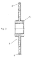
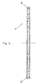
- the tool shown in FIGS. 1 and 2 for chamfering and deburring the Front tooth edges of straight and helical gears consists of a first and second roller gear 1 and 2, which between them a first and Pick up the second pane parts 3 and 4.
- the first and second disc parts 3 and 4 together form a combined driving and smoothing wheel.
- the first pane part 3 is provided on both sides with hub-like projections 5 on which the first roller gear 1 or the second disc part 4 and the second roller gear 2 can be rotated are put on. It can be seen that the contact surfaces of the first and second Rolling gear 1 and 2 and the first and second disc parts 3 and 4 in relation lie on the axis of rotation 6 of the tool in parallel radial planes.
- the first and second roller gear 1 and 2 are with over a circumferential range of about 160 ° Provide teeth 7 into the tooth spaces of a gear-like (not shown) Intervene workpiece and deburr the tooth's leading edges and / or chamfer.
- the first and the second disc parts 3 and 4 are over a peripheral region of approximately 170 ° with teeth 8 which fit into the tooth spaces of the (not engage) gear.
- This area of the first and second disk part 3 and 4 has the function of a guide wheel.
- the first and second disk parts 3 and 4 are of a conical shape of approximately 190 ° ground teeth 9 provided in the tooth spaces of the gear (not shown) intervention.
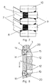
- This peripheral region of the first and second disk part 3 and 4 has the function of a smoothing wheel in that the conical teeth 9 possibly one secondary ridge generated by the rolling gear 1 or 2 on the flanks of the Remove teeth 10 of the workpiece (see Fig. 7). It can be seen that the first and second disc parts 3 and 4 in that provided with the conical teeth 9 Circumferential area is widened and an outwardly projecting ring flange having.
- the first roller gear 1 and the first disc part 3 and the second roller gear 2 and the second disc part 4 are assembled in such a rotational position, that the circumferential region provided with conical teeth 9 Disk parts 3 and 4 the toothless circumferential area of the gear wheels 1 and 2 opposite.
- the two disc parts 3 and 4 are at 180 ° to each other staggered so that one serving with the teeth 8th circumferential area provided with a smoothing conical teeth 9 provided circumferential area is opposite. This arrangement is a ensures smoother running during machining.
- the tapered teeth 9 of the first and second disc parts 3 and 4 the task involved in chamfering the Teeth 10 of the workpiece through the teeth 7 of the first and second roller gear 1 and 2 to eliminate possibly created ridges. So this elimination the burr throws, also known as secondary ridges, work perfectly, the conical teeth 9 of the first and second disk part 3, 4 in one very specific relative position to the teeth 10 of the workpiece. This Relative position depends on the helix angle of the workpiece. From the beginning reasons mentioned, the helix angle of the workpiece is subject to certain Fluctuations. With the individual batches of the workpieces to be processed therefore there are slightly different helix angles.
- the two can take fluctuations in the helix angle into account combined drive wheel and smoothing wheel forming disc parts 3 and 4 relative to each other be twisted.
- the conical teeth 9 of the two disc parts 3 and 4 can change of the helix angle of the workpiece can be compensated. This ensures that the conical teeth 9 of the two disc parts 3 and 4 with the teeth 10 of the workpiece properly engage, possibly at the Chamfer the front edges of burrs created.
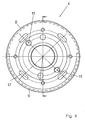
- two threaded bores 11 are provided at a radial distance from the axis of rotation 6.
- two bores 12 are provided, but in comparison to the threaded bores 11 have a different angular distance.
- the threaded holes 11 can therefore are only partially covered with the holes 12.
- Divided by two Elongated holes 13 in the second roller gear 2 are two adjusting screws 14 in the two threaded holes 11 of the second disc part 4 screwed.
- the two Adjusting screws 14 have a tapered shoulder 15 which is assigned to the Bore 12 of the first disc part 3 protrudes.
- the threaded holes 11 in the second disc part 4 under one Angular distance of 180 ° arranged, whereas the holes 12 in the first Disk part 3 are arranged at an angular distance of approximately 175 °. It is coming but only that the two threaded holes 11 with the holes 12 can only be partially covered, and that partially overlapping bores each have the same radial distance from the axis of rotation 6 of the tool.
- first disc part 3 there are also four threaded bores 16 in the radial direction Distance to the axis of rotation 6 is provided, and in the second disc part 4 are in the same radial distance four slots 17 are provided.
- Elongated holes 18 in the second roller gear 2 are clamping screws 19 in the threaded holes 16 of the first disc part 3 screwed.
- the first pane part can 3 be provided with a collar, so that between the two disc parts 3 and 4 a groove is formed.
- This groove is advantageous in eliminating the Machining the front edges of the chips that would otherwise occur in the tooth flanks of the workpiece could be pressed in.
- an additional third disc part be, which is only provided with teeth serving for guidance.
- the two Disc parts 3 and 4 trained teeth 9 an easy to produce wedge profile to have.
- Serving teeth can be easily adjusted to the respective helix angle of the machined workpiece. This is due to a relative twist of the two disc parts 3 and 4 causes. This relative rotation to Compensation for fluctuations in the helix angle of the workpieces to be machined different batches is very small.
- the proper intervention of the Guiding teeth 8 of the two disc parts 3 and 4 and the teeth 7 of the this does not result in two gear wheels 1 and 2 with the teeth 10 of the workpiece impaired.
Claims (3)
- Outil de chanfreinage et d'ébavurage des flancs extrêmes de roues dentées à dentures droite et oblique, comprenant au moins une roue d'ébarbage (1, 2) qui usine les flancs des dents et est agencée frontalement vis-à-vis de la pièce à travailler, dans laquelle elle engrène ; et un disque denté d'espacement qui jouxte axialement la roue d'ébarbage à laquelle il est relié avec verrouillage rotatif, engrène dans la pièce à travailler, et est réalisé sous la forme d'une roue d'entraínement (8) sur une partie du pourtour et, sur la partie restante du pourtour, sous la forme d'une roue de lissage (9) usinant les zones marginales des flancs des dents, caractérisé par le fait que le disque d'espacement est scindé en au moins deux disques (3, 4) reliés l'un à l'autre avec faculté de réglage en rotation.
- Outil selon la revendication 1, caractérisé par le fait que les deux disques (3, 4) sont décalés dans le sens périphérique, de façon telle que la région (9) de l'un des disques, servant de roue de lissage, se trouve en vis-à-vis de la région (8) de l'autre disque, servant de roue d'entraínement.
- Outil selon la revendication 1 ou 2, caractérisé par le fait que l'un (4) des disques est muni de deux trous taraudés (11) décalés dans le sens périphérique ; par le fait que l'autre disque (3) est pourvu de deux perçages (12) présentant un espacement angulaire autre que celui des trous taraudés (11) avec lesquels ils sont partiellement en chevauchement ; et par le fait que des vis de réglage (14) à pointeau tronconique (15) sont vissées dans les trous taraudés (11) de l'un (4) des disques, de telle sorte que les pointeaux tronconiques (15) ne touchent les bords (20) des perçages (12) de l'autre disque (3) que par une zone partielle.
Applications Claiming Priority (2)
| Application Number | Priority Date | Filing Date | Title |
|---|---|---|---|
| DE10129853 | 2001-06-21 | ||
| DE10129853A DE10129853C1 (de) | 2001-06-21 | 2001-06-21 | Werkzeug zum Anfasen und Entgraten der stirnseitigen Zahnkanten von Zahnrädern |
Publications (2)
| Publication Number | Publication Date |
|---|---|
| EP1270127A1 EP1270127A1 (fr) | 2003-01-02 |
| EP1270127B1 true EP1270127B1 (fr) | 2004-06-09 |
Family
ID=7688903
Family Applications (1)
| Application Number | Title | Priority Date | Filing Date |
|---|---|---|---|
| EP02008117A Expired - Lifetime EP1270127B1 (fr) | 2001-06-21 | 2002-04-11 | Outil de chanfreinage et d'ébavurage des extrémités frontales de dents des roues dentées |
Country Status (7)
| Country | Link |
|---|---|
| US (1) | US6676337B2 (fr) |
| EP (1) | EP1270127B1 (fr) |
| JP (1) | JP3816837B2 (fr) |
| AT (1) | ATE268662T1 (fr) |
| DE (2) | DE10129853C1 (fr) |
| ES (1) | ES2219600T3 (fr) |
| PT (1) | PT1270127E (fr) |
Cited By (1)
| Publication number | Priority date | Publication date | Assignee | Title |
|---|---|---|---|---|
| WO2021156355A1 (fr) | 2020-02-07 | 2021-08-12 | Profiroll Technologies Gmbh | Outil de laminage et procédé de laminage d'un profilé |
Families Citing this family (17)
| Publication number | Priority date | Publication date | Assignee | Title |
|---|---|---|---|---|
| CN100411791C (zh) * | 2006-06-29 | 2008-08-20 | 贵州群建齿轮有限公司 | 去除滚齿毛刺的机械装置 |
| JP5162920B2 (ja) * | 2007-02-19 | 2013-03-13 | マツダ株式会社 | 歯車の加工方法及び歯車加工装置 |
| DE102007021192A1 (de) * | 2007-05-05 | 2008-11-06 | Zf Friedrichshafen Ag | Zahnwellenverbindung zwischen einer Profiwelle und einer Nabe |
| JP2009172736A (ja) * | 2008-01-28 | 2009-08-06 | Nachi Fujikoshi Corp | フレージングツールを有する歯車端面面取り加工工具 |
| DE102009018405A1 (de) * | 2009-04-22 | 2010-10-28 | The Gleason Works | Verfahren und Vorrichtung zum Beseitigen eines Sekundärgrates an einem stirnverzahnten Werkstückrad |
| DE102009018392A1 (de) | 2009-04-22 | 2010-10-28 | The Gleason Works | Anordnung zur Verbindung eines Werkzeugrads und einer Werkzeugaufnahme |
| JP5460115B2 (ja) | 2009-04-28 | 2014-04-02 | 第一工業製薬株式会社 | 難燃性発泡スチレン系樹脂粒子およびその製造方法 |
| DE102012012559A1 (de) | 2012-06-25 | 2014-01-02 | Gleason-Pfauter Maschinenfabrik Gmbh | Verfahren zum Bearbeiten eines Werkstücks und dazu geeignete Verzahnungsmaschine |
| DE102013012797A1 (de) * | 2013-07-31 | 2015-02-19 | Gleason-Pfauter Maschinenfabrik Gmbh | Verfahren zum Bearbeiten von Zahnkanten und dazu ausgelegte Bearbeitungsstation |
| DE102013218542B4 (de) * | 2013-09-16 | 2015-09-24 | Felsomat Gmbh & Co Kg | Verfahren zum Anfasen und Glätten von verzahnten Werkstücken und zugehörige Bearbeitungsstation |
| DE102014218082B4 (de) | 2014-09-10 | 2016-11-10 | Felsomat Gmbh & Co. Kg | Vorrichtung zur Wälzschälbearbeitung eines Werkstücks zur Fertigung einer Fase und zugehöriges Betriebsverfahren |
| DE102014018328B4 (de) * | 2014-12-10 | 2023-03-02 | Gleason-Pfauter Maschinenfabrik Gmbh | Verfahren zum bearbeiten einer verzahnung, werkzeuganordnung und verzahnungsmaschine |
| DE102015013497A1 (de) | 2015-10-16 | 2017-04-20 | Gleason-Pfauter Maschinenfabrik Gmbh | Verfahren zum bearbeiten einer verzahnung und anordnung dafür |
| DE102016004112A1 (de) | 2016-04-05 | 2017-10-05 | Gleason-Pfauter Maschinenfabrik Gmbh | Verfahren zur erzeugung einer abtragung an einer zahnstirnkante und dazu ausgelegte vorrichtung |
| JP2021525655A (ja) | 2018-05-25 | 2021-09-27 | ザ グリーソン ワークス | 歯付きワークピース用の多工具面取り装置 |
| CN111230225A (zh) * | 2020-03-03 | 2020-06-05 | 重庆华陵工业有限公司 | 一种旋转定位型传动齿轮齿端部去毛刺倒角装置 |
| DE102020001428A1 (de) | 2020-03-05 | 2021-09-09 | Gleason-Pfauter Maschinenfabrik Gmbh | Verfahren zur Zahnkantenbearbeitung |
Family Cites Families (6)
| Publication number | Priority date | Publication date | Assignee | Title |
|---|---|---|---|---|
| DE2219770C2 (de) * | 1972-04-22 | 1982-07-01 | Schwäbische Hüttenwerke GmbH, 7080 Aalen | Gegossene, belüftete Bremsscheibe und Vorrichtung zu ihrer Herstellung |
| CH676940A5 (fr) * | 1989-01-27 | 1991-03-28 | Maag Zahnraeder & Maschinen Ag | |
| DE4020611C1 (en) * | 1990-06-28 | 1991-05-23 | Carl Hurth Maschinen- Und Zahnradfabrik Gmbh & Co, 8000 Muenchen, De | Deburring tool for gear teeth - includes secondary burr removal tool coaxial to work axis, to be effective on bevel teeth |
| DE4441927C1 (de) * | 1994-11-24 | 1996-03-14 | Hurth Maschinen Werkzeuge | Verfahren zum Dreheinstellen zweier eine gemeinsame Drehachse aufweisender Maschinenteile relativ zueinander, insbes. in einer Vorrichtung zum Entgraten von Zahnrädern, und eine solche Vorrichtung |
| DE29715092U1 (de) * | 1997-08-22 | 1997-10-23 | Gleason Works | Vorrichtung zum Anfassen und Entgraten der stirnseitigen Zahnkanten von Zahnrädern |
| IT1309965B1 (it) * | 1999-04-09 | 2002-02-05 | Samputensili Spa | Metodo si smussatura e sbavatura di denti di ruote dentate,dispositivo per l'attuazione di tale metodo e relativo utensile |
-
2001
- 2001-06-21 DE DE10129853A patent/DE10129853C1/de not_active Expired - Fee Related
-
2002
- 2002-04-11 DE DE50200506T patent/DE50200506D1/de not_active Expired - Lifetime
- 2002-04-11 EP EP02008117A patent/EP1270127B1/fr not_active Expired - Lifetime
- 2002-04-11 PT PT02008117T patent/PT1270127E/pt unknown
- 2002-04-11 ES ES02008117T patent/ES2219600T3/es not_active Expired - Lifetime
- 2002-04-11 AT AT02008117T patent/ATE268662T1/de not_active IP Right Cessation
- 2002-05-09 US US10/141,726 patent/US6676337B2/en not_active Expired - Lifetime
- 2002-06-20 JP JP2002179707A patent/JP3816837B2/ja not_active Expired - Fee Related
Cited By (2)
| Publication number | Priority date | Publication date | Assignee | Title |
|---|---|---|---|---|
| WO2021156355A1 (fr) | 2020-02-07 | 2021-08-12 | Profiroll Technologies Gmbh | Outil de laminage et procédé de laminage d'un profilé |
| DE102020103151A1 (de) | 2020-02-07 | 2021-08-12 | Profiroll Technologies Gmbh | Walzwerkzeug und Verfahren zum Walzen eines Profils |
Also Published As
| Publication number | Publication date |
|---|---|
| PT1270127E (pt) | 2004-10-29 |
| ATE268662T1 (de) | 2004-06-15 |
| ES2219600T3 (es) | 2004-12-01 |
| JP2003019621A (ja) | 2003-01-21 |
| DE10129853C1 (de) | 2003-01-09 |
| DE50200506D1 (de) | 2004-07-15 |
| EP1270127A1 (fr) | 2003-01-02 |
| JP3816837B2 (ja) | 2006-08-30 |
| US20020197118A1 (en) | 2002-12-26 |
| US6676337B2 (en) | 2004-01-13 |
Similar Documents
| Publication | Publication Date | Title |
|---|---|---|
| EP1270127B1 (fr) | Outil de chanfreinage et d'ébavurage des extrémités frontales de dents des roues dentées | |
| DE10330474B4 (de) | Vorrichtung zur Herstellung eines Zahnrads aus einem Zahnradrohling | |
| EP2243582B1 (fr) | Procédé et dispositif d'élimination d'un appareil secondaire sur une roue de pièce usinée interdigitée à l'avant | |
| EP3233343B1 (fr) | Procédé de taillage en développante et outil de coupe pour générer des têtes de dent au moins partiellement arrondies | |
| EP3439819B1 (fr) | Procédé de chanfreinage par enlèvement de matière d'une arête frontale de denture d'engrenage et dispositif conçu à cet effet | |
| EP1924383B1 (fr) | Systeme d'outil pour produire une denture helicoidale sur des roues droites | |
| DE102007015357A1 (de) | Verfahren und Vorrichtung zum Verzahnen von Werkstücken durch Wälzschälen und zugehöriger Schneidvorrichtung | |
| EP0542026B1 (fr) | Procédé d'usinage de surface à symétrie de rotation, en particulier vilebrequin, ainsi que outil pour la réalisation d'un tel procédé | |
| EP1533078B1 (fr) | Outil de meulage scindé | |
| WO2008052503A1 (fr) | Fraise dégrossisseuse et finisseuse | |
| EP3694670B1 (fr) | Outil de taillage en développante | |
| DE20320294U1 (de) | Vorrichtung zur Herstellung eines Zahnrads | |
| DE102004022360B4 (de) | Verfahren zur Feinbearbeitung, vorzugsweise zur Feinstschlichtbearbeitung, von Werkstücken vorzugsweise von Kurbelwellen | |
| DE10220513B4 (de) | Verfahren zum Abrichten oder Profilieren einer zylindrischen oder im wesentlichen zylindrischen Schleifschnecke | |
| EP3620251B1 (fr) | Procédé d'usinage de denture d'une pièce à usiner, machine à tailler les engrenages et logiciel correspondant | |
| CH664716A5 (de) | Verfahren und einrichtung zur bearbeitung der zahnflanken eines rotierenden, verzahnten werkstuecks. | |
| DE8328237U1 (de) | Vorrichtung zum entgraten oder brechen der stirnseitigen zahnkanten von zahnraedern | |
| DE10027011A1 (de) | Verfahren und Vorrichtung zum Hartfeinbearbeiten der Stirnverzahnung eines Zahnrades | |
| DE3236440C2 (fr) | ||
| DE102008036549A1 (de) | Welle und Welle-Nabe-Verbindung | |
| DE4030789A1 (de) | Verfahren und vorrichtung zur herstellung eines hauptrotors | |
| DE4441927C1 (de) | Verfahren zum Dreheinstellen zweier eine gemeinsame Drehachse aufweisender Maschinenteile relativ zueinander, insbes. in einer Vorrichtung zum Entgraten von Zahnrädern, und eine solche Vorrichtung | |
| DE10324432B4 (de) | Profilgeschärftes Stabmesser zur Herstellung von Kegel- und Hypoidrädern und Verfahren zum Profilschärfen eines solchen Stabmessers | |
| DE19942272C1 (de) | Fräswerkzeug | |
| DE2534574A1 (de) | Vorrichtung zum entgraten oder brechen der stirnkanten von zahnraedern |
Legal Events
| Date | Code | Title | Description |
|---|---|---|---|
| PUAI | Public reference made under article 153(3) epc to a published international application that has entered the european phase |
Free format text: ORIGINAL CODE: 0009012 |
|
| AK | Designated contracting states |
Kind code of ref document: A1 Designated state(s): AT BE CH CY DE DK ES FI FR GB GR IE IT LI LU MC NL PT SE TR |
|
| AX | Request for extension of the european patent |
Free format text: AL;LT;LV;MK;RO;SI |
|
| 17P | Request for examination filed |
Effective date: 20030415 |
|
| AKX | Designation fees paid |
Designated state(s): AT BE CH CY DE DK ES FI FR GB GR IE IT LI LU MC NL PT SE TR |
|
| GRAP | Despatch of communication of intention to grant a patent |
Free format text: ORIGINAL CODE: EPIDOSNIGR1 |
|
| GRAS | Grant fee paid |
Free format text: ORIGINAL CODE: EPIDOSNIGR3 |
|
| GRAA | (expected) grant |
Free format text: ORIGINAL CODE: 0009210 |
|
| AK | Designated contracting states |
Kind code of ref document: B1 Designated state(s): AT BE CH CY DE DK ES FI FR GB GR IE IT LI LU MC NL PT SE TR |
|
| PG25 | Lapsed in a contracting state [announced via postgrant information from national office to epo] |
Ref country code: TR Free format text: LAPSE BECAUSE OF FAILURE TO SUBMIT A TRANSLATION OF THE DESCRIPTION OR TO PAY THE FEE WITHIN THE PRESCRIBED TIME-LIMIT Effective date: 20040609 Ref country code: IE Free format text: LAPSE BECAUSE OF FAILURE TO SUBMIT A TRANSLATION OF THE DESCRIPTION OR TO PAY THE FEE WITHIN THE PRESCRIBED TIME-LIMIT Effective date: 20040609 Ref country code: NL Free format text: LAPSE BECAUSE OF FAILURE TO SUBMIT A TRANSLATION OF THE DESCRIPTION OR TO PAY THE FEE WITHIN THE PRESCRIBED TIME-LIMIT Effective date: 20040609 Ref country code: FI Free format text: LAPSE BECAUSE OF FAILURE TO SUBMIT A TRANSLATION OF THE DESCRIPTION OR TO PAY THE FEE WITHIN THE PRESCRIBED TIME-LIMIT Effective date: 20040609 |
|
| REG | Reference to a national code |
Ref country code: GB Ref legal event code: FG4D Free format text: NOT ENGLISH |
|
| REG | Reference to a national code |
Ref country code: CH Ref legal event code: EP |
|
| REF | Corresponds to: |
Ref document number: 50200506 Country of ref document: DE Date of ref document: 20040715 Kind code of ref document: P |
|
| REG | Reference to a national code |
Ref country code: IE Ref legal event code: FG4D Free format text: GERMAN |
|
| PG25 | Lapsed in a contracting state [announced via postgrant information from national office to epo] |
Ref country code: DK Free format text: LAPSE BECAUSE OF FAILURE TO SUBMIT A TRANSLATION OF THE DESCRIPTION OR TO PAY THE FEE WITHIN THE PRESCRIBED TIME-LIMIT Effective date: 20040909 Ref country code: GR Free format text: LAPSE BECAUSE OF FAILURE TO SUBMIT A TRANSLATION OF THE DESCRIPTION OR TO PAY THE FEE WITHIN THE PRESCRIBED TIME-LIMIT Effective date: 20040909 |
|
| GBT | Gb: translation of ep patent filed (gb section 77(6)(a)/1977) |
Effective date: 20040824 |
|
| REG | Reference to a national code |
Ref country code: SE Ref legal event code: TRGR |
|
| REG | Reference to a national code |
Ref country code: PT Ref legal event code: SC4A Free format text: AVAILABILITY OF NATIONAL TRANSLATION Effective date: 20040820 |
|
| NLV1 | Nl: lapsed or annulled due to failure to fulfill the requirements of art. 29p and 29m of the patents act | ||
| REG | Reference to a national code |
Ref country code: ES Ref legal event code: FG2A Ref document number: 2219600 Country of ref document: ES Kind code of ref document: T3 |
|
| REG | Reference to a national code |
Ref country code: IE Ref legal event code: FD4D |
|
| ET | Fr: translation filed | ||
| PG25 | Lapsed in a contracting state [announced via postgrant information from national office to epo] |
Ref country code: CY Free format text: LAPSE BECAUSE OF FAILURE TO SUBMIT A TRANSLATION OF THE DESCRIPTION OR TO PAY THE FEE WITHIN THE PRESCRIBED TIME-LIMIT Effective date: 20050411 Ref country code: LU Free format text: LAPSE BECAUSE OF NON-PAYMENT OF DUE FEES Effective date: 20050411 |
|
| PG25 | Lapsed in a contracting state [announced via postgrant information from national office to epo] |
Ref country code: SE Free format text: LAPSE BECAUSE OF NON-PAYMENT OF DUE FEES Effective date: 20050412 Ref country code: ES Free format text: LAPSE BECAUSE OF NON-PAYMENT OF DUE FEES Effective date: 20050412 |
|
| PLBE | No opposition filed within time limit |
Free format text: ORIGINAL CODE: 0009261 |
|
| STAA | Information on the status of an ep patent application or granted ep patent |
Free format text: STATUS: NO OPPOSITION FILED WITHIN TIME LIMIT |
|
| PG25 | Lapsed in a contracting state [announced via postgrant information from national office to epo] |
Ref country code: MC Free format text: LAPSE BECAUSE OF NON-PAYMENT OF DUE FEES Effective date: 20050430 |
|
| 26N | No opposition filed |
Effective date: 20050310 |
|
| EUG | Se: european patent has lapsed | ||
| PG25 | Lapsed in a contracting state [announced via postgrant information from national office to epo] |
Ref country code: PT Free format text: LAPSE BECAUSE OF NON-PAYMENT OF DUE FEES Effective date: 20060111 |
|
| PG25 | Lapsed in a contracting state [announced via postgrant information from national office to epo] |
Ref country code: LI Free format text: LAPSE BECAUSE OF NON-PAYMENT OF DUE FEES Effective date: 20060430 Ref country code: CH Free format text: LAPSE BECAUSE OF NON-PAYMENT OF DUE FEES Effective date: 20060430 |
|
| REG | Reference to a national code |
Ref country code: ES Ref legal event code: FD2A Effective date: 20050412 |
|
| REG | Reference to a national code |
Ref country code: CH Ref legal event code: PL |
|
| PGFP | Annual fee paid to national office [announced via postgrant information from national office to epo] |
Ref country code: AT Payment date: 20070314 Year of fee payment: 6 |
|
| PGFP | Annual fee paid to national office [announced via postgrant information from national office to epo] |
Ref country code: GB Payment date: 20080317 Year of fee payment: 7 |
|
| PG25 | Lapsed in a contracting state [announced via postgrant information from national office to epo] |
Ref country code: PT Free format text: LAPSE BECAUSE OF NON-PAYMENT OF DUE FEES Effective date: 20050411 |
|
| PG25 | Lapsed in a contracting state [announced via postgrant information from national office to epo] |
Ref country code: AT Free format text: LAPSE BECAUSE OF NON-PAYMENT OF DUE FEES Effective date: 20080411 |
|
| GBPC | Gb: european patent ceased through non-payment of renewal fee |
Effective date: 20090411 |
|
| PG25 | Lapsed in a contracting state [announced via postgrant information from national office to epo] |
Ref country code: GB Free format text: LAPSE BECAUSE OF NON-PAYMENT OF DUE FEES Effective date: 20090411 |
|
| PGFP | Annual fee paid to national office [announced via postgrant information from national office to epo] |
Ref country code: FR Payment date: 20110331 Year of fee payment: 10 |
|
| REG | Reference to a national code |
Ref country code: FR Ref legal event code: ST Effective date: 20121228 |
|
| PG25 | Lapsed in a contracting state [announced via postgrant information from national office to epo] |
Ref country code: FR Free format text: LAPSE BECAUSE OF NON-PAYMENT OF DUE FEES Effective date: 20120430 |
|
| PGFP | Annual fee paid to national office [announced via postgrant information from national office to epo] |
Ref country code: DE Payment date: 20200429 Year of fee payment: 19 |
|
| PGFP | Annual fee paid to national office [announced via postgrant information from national office to epo] |
Ref country code: BE Payment date: 20200427 Year of fee payment: 19 Ref country code: IT Payment date: 20200423 Year of fee payment: 19 |
|
| REG | Reference to a national code |
Ref country code: DE Ref legal event code: R119 Ref document number: 50200506 Country of ref document: DE |
|
| REG | Reference to a national code |
Ref country code: BE Ref legal event code: MM Effective date: 20210430 |
|
| PG25 | Lapsed in a contracting state [announced via postgrant information from national office to epo] |
Ref country code: DE Free format text: LAPSE BECAUSE OF NON-PAYMENT OF DUE FEES Effective date: 20211103 |
|
| PG25 | Lapsed in a contracting state [announced via postgrant information from national office to epo] |
Ref country code: BE Free format text: LAPSE BECAUSE OF NON-PAYMENT OF DUE FEES Effective date: 20210430 |
|
| PG25 | Lapsed in a contracting state [announced via postgrant information from national office to epo] |
Ref country code: IT Free format text: LAPSE BECAUSE OF NON-PAYMENT OF DUE FEES Effective date: 20200411 |