EP1270127B1 - Tool for chamfering and deburring frontal tooth ends of gears - Google Patents
Tool for chamfering and deburring frontal tooth ends of gears Download PDFInfo
- Publication number
- EP1270127B1 EP1270127B1 EP02008117A EP02008117A EP1270127B1 EP 1270127 B1 EP1270127 B1 EP 1270127B1 EP 02008117 A EP02008117 A EP 02008117A EP 02008117 A EP02008117 A EP 02008117A EP 1270127 B1 EP1270127 B1 EP 1270127B1
- Authority
- EP
- European Patent Office
- Prior art keywords
- disc
- wheel
- workpiece
- tool
- smoothing
- Prior art date
- Legal status (The legal status is an assumption and is not a legal conclusion. Google has not performed a legal analysis and makes no representation as to the accuracy of the status listed.)
- Expired - Lifetime
Links
Images


Classifications
-
- B—PERFORMING OPERATIONS; TRANSPORTING
- B23—MACHINE TOOLS; METAL-WORKING NOT OTHERWISE PROVIDED FOR
- B23F—MAKING GEARS OR TOOTHED RACKS
- B23F19/00—Finishing gear teeth by other tools than those used for manufacturing gear teeth
- B23F19/10—Chamfering the end edges of gear teeth
-
- Y—GENERAL TAGGING OF NEW TECHNOLOGICAL DEVELOPMENTS; GENERAL TAGGING OF CROSS-SECTIONAL TECHNOLOGIES SPANNING OVER SEVERAL SECTIONS OF THE IPC; TECHNICAL SUBJECTS COVERED BY FORMER USPC CROSS-REFERENCE ART COLLECTIONS [XRACs] AND DIGESTS
- Y10—TECHNICAL SUBJECTS COVERED BY FORMER USPC
- Y10T—TECHNICAL SUBJECTS COVERED BY FORMER US CLASSIFICATION
- Y10T407/00—Cutters, for shaping
- Y10T407/17—Gear cutting tool
- Y10T407/1735—Rotary, gear shaving cutting tool
-
- Y—GENERAL TAGGING OF NEW TECHNOLOGICAL DEVELOPMENTS; GENERAL TAGGING OF CROSS-SECTIONAL TECHNOLOGIES SPANNING OVER SEVERAL SECTIONS OF THE IPC; TECHNICAL SUBJECTS COVERED BY FORMER USPC CROSS-REFERENCE ART COLLECTIONS [XRACs] AND DIGESTS
- Y10—TECHNICAL SUBJECTS COVERED BY FORMER USPC
- Y10T—TECHNICAL SUBJECTS COVERED BY FORMER US CLASSIFICATION
- Y10T409/00—Gear cutting, milling, or planing
- Y10T409/10—Gear cutting
- Y10T409/101113—Gear chamfering or deburring
-
- Y—GENERAL TAGGING OF NEW TECHNOLOGICAL DEVELOPMENTS; GENERAL TAGGING OF CROSS-SECTIONAL TECHNOLOGIES SPANNING OVER SEVERAL SECTIONS OF THE IPC; TECHNICAL SUBJECTS COVERED BY FORMER USPC CROSS-REFERENCE ART COLLECTIONS [XRACs] AND DIGESTS
- Y10—TECHNICAL SUBJECTS COVERED BY FORMER USPC
- Y10T—TECHNICAL SUBJECTS COVERED BY FORMER US CLASSIFICATION
- Y10T409/00—Gear cutting, milling, or planing
- Y10T409/10—Gear cutting
- Y10T409/107632—Gear shaving
Definitions
- the invention relates to a tool for chamfering and deburring the front Tooth edges of straight and helical gears (see, for example DE 4020611) with at least one arranged on the face of the workpiece and meshing with it, the Tooth edge machining roller gear, an axially arranged next to the roller gear, with this non-rotatably connected and meshing with the workpiece toothed spacer, which over part of the circumference as a driving wheel and working over the remaining part of the circumference as the edge zones of the tooth flanks Smoothing wheel is formed.
- the invention has for its object the generic tool to further develop that there is an adaptation to fluctuations in the helix angle of the gears to be machined.
- this object is achieved in that the spacer is divided into at least two disks, which are rotatably connected to each other are.
- the inventive design of the tool enables the user react immediately to fluctuations in the helix angle on the workpiece.
- the relative position of the two disks is changed so that the teeth arranged in the smoothing area on the tooth flanks of the workpiece properly get to the plant and eliminate the secondary degree there. Since each of the two discs only one of the two edges of each tooth flank of the Machined workpiece, the hollow grinding required for a one-piece smoothing wheel the flank lines are eliminated
- the two disks of the tool according to the invention are preferred arranged offset in the circumferential direction so that the area serving as a smoothing wheel one disc the area of the other disc that serves as a driving wheel opposite. This ensures a smoother running during processing.
- the smoothing and deburring results of each plan page can be targeted can be set.
- the chamfer widths and the helix angle of the Smoothing range can be optimized independently.
- Threaded holes are provided that the other disc with two holes is provided, which have a different angular distance than the threaded holes and partially overlap with these, and that in the threaded holes a washer screws with a tapered shoulder are screwed in, such that the tapered lugs only the edges of the holes in the other disc touch a section.
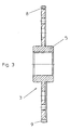
- the tool shown in FIGS. 1 and 2 for chamfering and deburring the Front tooth edges of straight and helical gears consists of a first and second roller gear 1 and 2, which between them a first and Pick up the second pane parts 3 and 4.
- the first and second disc parts 3 and 4 together form a combined driving and smoothing wheel.
- the first pane part 3 is provided on both sides with hub-like projections 5 on which the first roller gear 1 or the second disc part 4 and the second roller gear 2 can be rotated are put on. It can be seen that the contact surfaces of the first and second Rolling gear 1 and 2 and the first and second disc parts 3 and 4 in relation lie on the axis of rotation 6 of the tool in parallel radial planes.
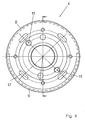
- the first and second roller gear 1 and 2 are with over a circumferential range of about 160 ° Provide teeth 7 into the tooth spaces of a gear-like (not shown) Intervene workpiece and deburr the tooth's leading edges and / or chamfer.
- the first and the second disc parts 3 and 4 are over a peripheral region of approximately 170 ° with teeth 8 which fit into the tooth spaces of the (not engage) gear.
- This area of the first and second disk part 3 and 4 has the function of a guide wheel.
- the first and second disk parts 3 and 4 are of a conical shape of approximately 190 ° ground teeth 9 provided in the tooth spaces of the gear (not shown) intervention.
- This peripheral region of the first and second disk part 3 and 4 has the function of a smoothing wheel in that the conical teeth 9 possibly one secondary ridge generated by the rolling gear 1 or 2 on the flanks of the Remove teeth 10 of the workpiece (see Fig. 7). It can be seen that the first and second disc parts 3 and 4 in that provided with the conical teeth 9 Circumferential area is widened and an outwardly projecting ring flange having.
- the first roller gear 1 and the first disc part 3 and the second roller gear 2 and the second disc part 4 are assembled in such a rotational position, that the circumferential region provided with conical teeth 9 Disk parts 3 and 4 the toothless circumferential area of the gear wheels 1 and 2 opposite.
- the two disc parts 3 and 4 are at 180 ° to each other staggered so that one serving with the teeth 8th circumferential area provided with a smoothing conical teeth 9 provided circumferential area is opposite. This arrangement is a ensures smoother running during machining.
- the tapered teeth 9 of the first and second disc parts 3 and 4 the task involved in chamfering the Teeth 10 of the workpiece through the teeth 7 of the first and second roller gear 1 and 2 to eliminate possibly created ridges. So this elimination the burr throws, also known as secondary ridges, work perfectly, the conical teeth 9 of the first and second disk part 3, 4 in one very specific relative position to the teeth 10 of the workpiece. This Relative position depends on the helix angle of the workpiece. From the beginning reasons mentioned, the helix angle of the workpiece is subject to certain Fluctuations. With the individual batches of the workpieces to be processed therefore there are slightly different helix angles.
- the two can take fluctuations in the helix angle into account combined drive wheel and smoothing wheel forming disc parts 3 and 4 relative to each other be twisted.
- the conical teeth 9 of the two disc parts 3 and 4 can change of the helix angle of the workpiece can be compensated. This ensures that the conical teeth 9 of the two disc parts 3 and 4 with the teeth 10 of the workpiece properly engage, possibly at the Chamfer the front edges of burrs created.
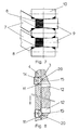
- two threaded bores 11 are provided at a radial distance from the axis of rotation 6.
- two bores 12 are provided, but in comparison to the threaded bores 11 have a different angular distance.
- the threaded holes 11 can therefore are only partially covered with the holes 12.
- Divided by two Elongated holes 13 in the second roller gear 2 are two adjusting screws 14 in the two threaded holes 11 of the second disc part 4 screwed.
- the two Adjusting screws 14 have a tapered shoulder 15 which is assigned to the Bore 12 of the first disc part 3 protrudes.
- the threaded holes 11 in the second disc part 4 under one Angular distance of 180 ° arranged, whereas the holes 12 in the first Disk part 3 are arranged at an angular distance of approximately 175 °. It is coming but only that the two threaded holes 11 with the holes 12 can only be partially covered, and that partially overlapping bores each have the same radial distance from the axis of rotation 6 of the tool.
- first disc part 3 there are also four threaded bores 16 in the radial direction Distance to the axis of rotation 6 is provided, and in the second disc part 4 are in the same radial distance four slots 17 are provided.
- Elongated holes 18 in the second roller gear 2 are clamping screws 19 in the threaded holes 16 of the first disc part 3 screwed.
- the first pane part can 3 be provided with a collar, so that between the two disc parts 3 and 4 a groove is formed.
- This groove is advantageous in eliminating the Machining the front edges of the chips that would otherwise occur in the tooth flanks of the workpiece could be pressed in.
- an additional third disc part be, which is only provided with teeth serving for guidance.
- the two Disc parts 3 and 4 trained teeth 9 an easy to produce wedge profile to have.
- Serving teeth can be easily adjusted to the respective helix angle of the machined workpiece. This is due to a relative twist of the two disc parts 3 and 4 causes. This relative rotation to Compensation for fluctuations in the helix angle of the workpieces to be machined different batches is very small.
- the proper intervention of the Guiding teeth 8 of the two disc parts 3 and 4 and the teeth 7 of the this does not result in two gear wheels 1 and 2 with the teeth 10 of the workpiece impaired.
Abstract
Description
Die Erfindung betrifft ein Werkzeug zum Anfasen und Entgraten der stirnseitigen Zahnkanten von gerad- und schrägverzahnten Zahnrädern (siehe, zum Beispiel DE 4020611) mit mindestens einem stirnseitig zum Werkstück angeordneten und mit diesem kämmenden, die Zahnkanten bearbeitenden Wälzgratrad, einer axial neben dem Wälzgratrad angeordneten, mit diesem drehfest verbundenen und mit dem Werkstück kämmenden verzahnten Distanzscheibe, die über einen Teil des Umfangs als Mitnahmerad und über den übrigen Teil des Umfangs als die Randzonen der Zahnflanken bearbeitendes Glättrad ausgebildet ist.The invention relates to a tool for chamfering and deburring the front Tooth edges of straight and helical gears (see, for example DE 4020611) with at least one arranged on the face of the workpiece and meshing with it, the Tooth edge machining roller gear, an axially arranged next to the roller gear, with this non-rotatably connected and meshing with the workpiece toothed spacer, which over part of the circumference as a driving wheel and working over the remaining part of the circumference as the edge zones of the tooth flanks Smoothing wheel is formed.
Ein derartiges Werkzeug ist aus dem Firmenprospekt "Gleason-HURTH Wälzentgratwerkzeuge"
bekannt. Bei spanend hergestellten Zahnrädern wird an den stirnseitigen
Zahnkanten ein Grat gebildet, der aus verschiedenen Gründen beseitigt
werden muß. Ein solcher Grat ist hinderlich, weil in den nachfolgenden Arbeitsgängen
eine Planfläche, z. B. die Stirnfläche des Zahnrades, oft als Spann- und
Bestimmungsfläche dienen soll. Ein besonderes Risiko für die Verzahnung ist ein
gehärteter Grat, der spätestens beim Lauf im Getriebe abspringt und die Zahnflanken
beschädigen kann. Ganz abgesehen davon, daß ein stehengebliebener Grat auch
eine Verletzungsgefahr beim Handhaben der Werkstücke darstellt. Aus diesen Gründen
werden bereits seit langem zahlreiche Verfahren und Vorrichtungen zum Entfernen
des Grates benützt. Doch genügt es zumeist nicht, nur die Grate zu beseitigen.
Beim Härten beispielsweise besteht die Gefahr, daß die spitze Kante durch Überkohlung
glashart wird und dann unter Belastung ausbricht. Deshalb muß die stirnseitige
Zahnkante zusätzlich mit einer Phase versehen werden; sie schützt zudem die
aktive Zahnoberfläche vor Beschädigungen. Dieses Ziel wird mit der gattungsgemäßen
Vorrichtung erreicht, indem Material des Werkstücks an der Kante zwischen der
Zahnflanke und der Stirnfläche verdrängt wird, um eine ein- oder zweiflankige Phase
zu erzeugen. Bei dieser plastischen Verformung wird das Material des Werkstücks
vom Wälzgratrad zur Stirnfläche hin und in die Zahnflanke verdrängt, wodurch ein
sogenannter Sekundärgrat entsteht. Dieser Sekundärgrat wurde früher mit einem
Schneidstahl stirnseitig und mit einem mit dem Werkstück kämmenden verzahnten
Glättrad beseitigt. Beim Stand der Technik war dieses Glättrad ein von dem mit dem
oder den Wälzgraträdern drehfest verbundenen Mitnahmerad unabhängiges Bauteil.
Aus dem eingangs erwähnten Firmenprospekt ist auch bereits ein gattungsgemäßes
Werkzeug bekannt, bei dem die mit dem oder den Wälzgraträdern drehfest verbundene
Distanzscheibe sowohl die Funktion des Mitnahmerades als auch die Funktion
des Glättrades übernimmt. Mann könnte daher auch von einem kombinierten Mitnahme-
und Glättrad sprechen. Um mit dem als Glättrad dienenden Umfangsbereich
der Distanzscheibe im Naß- und Trockenverfahren optimale Glättergebnisse zu
erzielen, muß der Schrägungswinkel der Verzahnung des Glättbereichs exakt demjenigen
des Werkstücks entsprechen. Wenn diese Voraussetzung nicht erfüllt ist,
dann entstehen Grataufwürfe in den Zahnflanken des Werkstücks, die bei einer
anschließenden Hartfeinbearbeitung zu einem vorzeitigen Verschleiß des Feinbearbeitungswerkzeugs
führen. Erfahrungsgemäß ändert sich der Schrägungswinkel der
zu bearbeitenden Werkstücke aber ständig aus folgenden Gründen:
Da der Anwender des gattungsgemäßen Werkzeugs vor Ort keine andere Möglichkeit hat, als den Achsabstand in der Entgratmaschine zu verändern, wird zumeist dieser Weg gewählt, der aber falsch ist. Bei einer Verringerung des Achsabstandes wird nämlich das Material am Werkstück derart verdichtet, daß ein Materialabtrag für eine nachfolgende Hartfeinbearbeitung sehr erschwert wird.. Dies bedeutet ebenfalls einen vorzeitigen Verschleiß des Werkzeugs. Wird hingegen der Achsabstand vergrößert, dann wächst dementsprechend der Grataufwurf.Since the user of the generic tool on site no other Possibility to change the center distance in the deburring machine this path is mostly chosen, but it is wrong. When the center distance is reduced the material on the workpiece is compacted in such a way that material is removed for a subsequent hard fine machining is very difficult .. This also means premature wear of the tool. However, if the Axis spacing increased, then the ridge rises accordingly.
Der Erfindung liegt die Aufgabe zugrunde, das gattungsgemäße Werkzeug dahingehend weiterzubilden, daß es eine Anpassung an Schwankungen des Schrägungswinkels der zu bearbeitenden Zahnräder ermöglicht.The invention has for its object the generic tool to further develop that there is an adaptation to fluctuations in the helix angle of the gears to be machined.
Erfindungsgemäß wird diese Aufgabe dadurch gelöst, daß die Distanzscheibe in mindestens zwei Scheiben unterteilt ist, die dreheinstellbar miteinander verbunden sind. Die erfindungsgemäße Ausbildung des Werkzeugs ermöglicht es dem Benutzer, auf Schwankungen des Schrägungswinkels am Werkstück sofort zu reagieren. Zu diesem Zweck wird die Relativstellung der beiden Scheiben so verändert, daß die im Glättbereich angeordneten Zähne an den Zahnflanken des Werkstücks ordnungsgemäß zur Anlage gelangen und den dort vorhandenen Sekundärgrad beseitigen. Da jede der beiden Scheiben nur einen der beiden Ränder jeder Zahnflanke des Werkstücks bearbeitet, kann das bei einem einteiligen Glättrad erforderliche Hohlschleifen der Flankenlinien entfallenAccording to the invention, this object is achieved in that the spacer is divided into at least two disks, which are rotatably connected to each other are. The inventive design of the tool enables the user react immediately to fluctuations in the helix angle on the workpiece. For this purpose, the relative position of the two disks is changed so that the teeth arranged in the smoothing area on the tooth flanks of the workpiece properly get to the plant and eliminate the secondary degree there. Since each of the two discs only one of the two edges of each tooth flank of the Machined workpiece, the hollow grinding required for a one-piece smoothing wheel the flank lines are eliminated
Die beiden Scheiben des erfindungsgemäßen Werkzeugs sind vorzugsweise in Umfangsrichtung so versetzt angeordnet, daß der als Glättrad dienende Bereich der einen Scheibe dem als Mitnahmerad dienenden Bereich der anderen Scheibe gegenüberliegt. Dadurch ist eine größere Laufruhe während der Bearbeitung gewährleistet. Außerdem können das Glätt- und Entgratergebnis jeder Planseite gezielt eingestellt werden. Ferner können die Fasenbreiten und der Schrägungswinkel des Glättbereichs unabhängig voneinander optimiert werden.The two disks of the tool according to the invention are preferred arranged offset in the circumferential direction so that the area serving as a smoothing wheel one disc the area of the other disc that serves as a driving wheel opposite. This ensures a smoother running during processing. In addition, the smoothing and deburring results of each plan page can be targeted can be set. Furthermore, the chamfer widths and the helix angle of the Smoothing range can be optimized independently.
Bei einer besonders vorteilhaften Ausführungsform des erfindungsgemäßen Werkzeugs ist vorgesehen, daß die eine Scheibe mit zwei in Umfangsrichtung versetzten Gewindebohrungen versehen ist, daß die andere Scheibe mit zwei Bohrungen versehen ist, die einen anderen Winkelabstand aufweisen als die Gewindebohrungen und mit diesen teilweise überlappen, und daß in die Gewindebohrungen der einen Scheibe Einstellschrauben mit kegeligem Ansatz eingeschraubt sind, derart, daß die kegeligen Ansätze die Ränder der Bohrungen der anderen Scheibe nur in einem Teilbereich berühren. Durch Eindrehen der einen Schraube und entsprechendes Herausdrehen der anderen Schraube kann eine Relativverdrehung der beiden Scheiben des Werkzeugs in einer Richtung erzielt werden.In a particularly advantageous embodiment of the invention Tool is provided that offset one disc with two in the circumferential direction Threaded holes are provided that the other disc with two holes is provided, which have a different angular distance than the threaded holes and partially overlap with these, and that in the threaded holes a washer screws with a tapered shoulder are screwed in, such that the tapered lugs only the edges of the holes in the other disc touch a section. By screwing in a screw and the like Unscrewing the other screw can cause a relative rotation of the two Disks of the tool can be achieved in one direction.
Ein bevorzugtes Ausführungsbeispiel der Erfindung ist in den Zeichnungen
dargestellt und wird nachfolgend näher erläutert. Es zeigt:
Das in den Fig. 1 und 2 gezeigte Werkzeug zum Anfasen und Entgraten der
stirnseitigen Zahnkanten von gerad- und schrägverzahnten Zahnrädern besteht aus
einem ersten und zweiten Wälzgratrad 1 und 2, die zwischen sich ein erstes und
zweites Scheibenteil 3 und 4 aufnehmen. Das erste und zweite Scheibenteil 3 und 4
bilden gemeinsam ein kombiniertes Mitnahme- und Glättrad. Das erste Scheibenteil
3 ist beidseitig mit nabenartigen Ansätzen 5 versehen, auf die das erste Wälzgratrad
1 bzw. das zweite Scheibenteil 4 und das zweite Wälzgratrad 2 verdreheinstellbar
aufgesetzt sind. Es ist erkennbar, daß die Berührungsflächen des ersten und zweiten
Wälzgratrades 1 und 2 und des ersten und zweiten Scheibenteils 3 und 4 in bezug
auf die Drehachse 6 des Werkzeugs in parallelen Radialebenen liegen. Das erste
und zweite Wälzgratrad 1 und 2 sind über einen Umfangsbereich von ca. 160° mit
Zähnen 7 versehen, die in die Zahnlücken eines (nicht gezeigten) zahnradartigen
Werkstücks eingreifen und dabei die Zahn-Stimkanten desselben entgraten und/oder
anfasen.The tool shown in FIGS. 1 and 2 for chamfering and deburring the
Front tooth edges of straight and helical gears consists of
a first and
Das erste und das zweite Scheibenteil 3 und 4 sind über einen Umfangsbereich
von ungefähr 170° mit Zähnen 8 versehen, die in die Zahnlücken des (nicht
gezeigten) Zahnrades eingreifen. Dieser Bereich des ersten und zweiten Scheibenteils
3 und 4 hat die Funktion eines Führungsrades. In dem verbleibenden Umfangsbereich
von ca. 190° sind das erste und das zweite Scheibenteil 3 und 4 mit konisch
geschliffenen Zähnen 9 versehen, die in die Zahnlücken des (nicht gezeigten) Zahnrades
eingreifen. Dieser Umfangsbereich des ersten und zweiten Scheibenteils 3 und
4 hat die Funktion eines Glättrades, indem die konischen Zähne 9 einen möglicherweise
von dem Wälzgratrad 1 bzw. 2 erzeugten Sekundärgrat an den Flanken der
Zähne 10 des Werkstücks beseitigen (siehe Fig. 7). Es ist erkennbar, daß das erste
und zweite Scheibenteil 3 und 4 in dem mit den konischen Zähnen 9 versehenen
Umfangsbereich verbreitert ist und einen nach außen vorspringenden Ringflansch
aufweist.The first and the
Das erste Wälzgratrad 1 und das erste Scheibenteil 3 bzw. das zweite Wälzgratrad
2 und das zweite Scheibenteil 4 werden in einer solchen Drehstellung zusammengefügt,
daß der mit konischen Zähnen 9 versehene Umfangsbereich der
Scheibenteile 3 und 4 dem zahnlosen Umfangsbereich der Wälzgraträder 1 und 2
gegenüberliegt. Außerdem sind die beiden Scheibenteile 3 und 4 um 180° zueinander
versetzt angeordnet, so daß jeweils ein mit der Führung dienenden Zähnen 8
versehener Umfangsbereich einem mit der Glättung dienenden konischen Zähnen 9
versehenen Umfangsbereich gegenüberliegt. Durch diese Anordnung ist eine
größere Laufruhe während der Bearbeitung gewährleistet.The
Wie dies vorstehend erläutert wurde, haben die konisch geschliffenen Zähne 9
des ersten und zweiten Scheibenteils 3 und 4 die Aufgabe, die beim Anfasen der
Zähne 10 des Werkstücks durch die Zähne 7 des ersten und zweiten Wälzgratrades
1 und 2 möglicherweise erzeugten Grataufwürfe zu beseitigen. Damit diese Beseitigung
der auch als Sekundärgrat bezeichneten Grataufwürfe einwandfrei abläuft,
müssen die konischen Zähne 9 des ersten und zweiten Scheibenteils 3, 4 in einer
ganz bestimmten Relativstellung zu den Zähnen 10 des Werkstücks stehen. Diese
Relativstellung hängt vom Schrägungswinkel des Werkstücks ab. Aus den eingangs
genannten Gründen unterliegt der Schrägungswinkel des Werkstücks aber gewissen
Schwankungen. Bei den einzelnen Chargen der zu bearbeitenden Werkstücke können
daher geringfügig unterschiedliche Schrägungswinkel vorliegen. Um diesen
Schwankungen des Schrägungswinkels Rechnung zu tragen, können die beiden, ein
kombiniertes Mitnahme- und Glättrad bildenden Scheibenteile 3 und 4 relativ zueinander
verdreht werden. Durch eine entsprechende Veränderung des Winkelabstandes
der konischen Zähne 9 der beiden Scheibenteile 3 und 4 kann eine Änderung
des Schrägungswinkels des Werkstücks kompensiert werden. Dadurch ist gewährleistet,
daß die konischen Zähne 9 der beiden Scheibenteile 3 und 4 mit den Zähnen 10
des Werkstücks ordnungsgemäß in Eingriff gelangen, um möglicherweise bei der
Anfasung der Stirnkanten erzeugte Grataufwürfe zu glätten.As explained above, the
Zum Einstellen der Relativstellung der das kombinierte Mitnahme- und
Glättrad bildenden beiden Scheibenteile 3 und 4 sind in dem zweiten Scheibenteil 4
mit radialem Abstand zur Drehachse 6 zwei Gewindebohrungen 11 vorgesehen. In
dem ersten Scheibenteil 3 sind mit dem gleichen radialen Abstand zur Drehachse 6
zwei Bohrungen 12 vorgesehen, die aber im Vergleich zu den Gewindebohrungen 11
einen anderen Winkelabstand aufweisen. Die Gewindebohrungen 11 können daher
mit den Bohrungen 12 nur teilweise zur Deckung gebracht werden. Durch zwei
Langlöcher 13 in dem zweiten Wälzgratrad 2 sind zwei Einstellschrauben 14 in die
beiden Gewindebohrungen 11 des zweiten Scheibenteils 4 eingeschraubt. Die beiden
Einstellschrauben 14 haben einen kegeligen Ansatz 15, der in die zugeordnete
Bohrung 12 des ersten Scheibenteils 3 hineinragt. Bei dem gezeigten Ausführungsbeispiel
sind die Gewindebohrungen 11 in dem zweiten Scheibenteil 4 unter einem
Winkelabstand von 180° angeordnet, wogegen die Bohrungen 12 in dem ersten
Scheibenteil 3 unter einem Winkelabstand von ca. 175° angeordnet sind. Es kommt
aber lediglich darauf an, daß die beiden Gewindebohrungen 11 mit den Bohrungen
12 nur teilweise zur Deckung gebracht werden können, und daß die sich teilweise
überlappenden Bohrungen jeweils den gleichen radialen Abstand zur Drehachse 6
des Werkzeugs haben.To set the relative position of the combined take-away and
Smoothing wheel forming two
In dem ersten Scheibenteil 3 sind ferner vier Gewindebohrungen 16 im radialen
Abstand zur Drehachse 6 vorgesehen, und in dem zweiten Scheibenteil 4 sind in
gleichen radialen Abstand vier Langlöcher 17 vorgesehen. Durch entsprechende
Langlöcher 18 in dem zweiten Wälzgratrad 2 sind Spannschrauben 19 in die Gewindebohrungen
16 des ersten Scheibenteils 3 eingeschraubt. Zur Einstellung der relativen
Verdrehung des das kombinierte Mitnahme- und Glättrad bildenden ersten und
zweiten Scheibenteils 3 und 4 werden bei gelösten Spannschrauben 19 die beiden
Einstellschrauben 14 so weit in die Gewindebohrungen 11 des zweiten Scheibenteils
4 eingeschraubt, daß beide kegeligen Ansätze 15 an einem Randbereich 20 der
Bohrungen 12 des ersten Scheibenteils 3 zur Anlage kommen (Fig. 8). Wenn das
zweite Scheibenteil 4 gegenüber dem ersten Scheibenteil 3 gemäß Fig. 8 in Pfeilrichtung
geringfügig verdreht werden soll, dann wird die untere Einstellschraube 14
wieder zurückgedreht, und die obere Einstellschraube 14 wird weiter eingeschraubt.
Dabei vergrößert sich der am Randbereich 20 der Bohrung 12 des ersten Scheibenteils
3 tangierend anliegende Durchmesser des kegeligen Ansatzes 15 der oberen
Einstellschraube 14 ständig und bewirkt so die relative Verdrehung des zweiten
Scheibenteils 4 gegenüber dem ersten Scheibenteil 3. Ist die gewünschte Relativstellung
erreicht, dann wird die untere Einstellschraube 14 wieder soweit eingeschraubt,
bis ihr kegeliger Ansatz 15 am Randbereich 20 der Bohrung 12 tangierend
anliegt und so ein ungewolltes Verändern der zuvor eingestellten Relativstellung verhindert.
Wenn der Einstellvorgang der relativen Drehstellung der beiden Scheibenteile
3 und 4 beendet ist, dann werden die Spannschrauben 19 angezogen.In the
Mit einem ähnlichen Einstellmechanismus, der gleichfalls zwei Einstellschrauben
21 umfaßt, kann die relative Drehstellung der beiden Wälzentgraträder 1 und 2
eingestellt werden. Mit Spannschrauben 22 können das erste und zweite Wälzgratrad
1, 2 und mit Spannschrauben 19 das erste und zweite Scheibenteil 3 und 4 in der
zuvor eingestellten Relativstellung drehfest miteinander verbunden werden.With a similar adjustment mechanism, which also has two adjustment screws
21 includes, the relative rotational position of the two
Abweichend von dem gezeigten Ausführungsbeispiel kann das erste Scheibenteil
3 mit einem Bund versehen sein, so daß zwischen den beiden Scheibenteilen
3 und 4 eine Nut gebildet wird. Diese Nut ist vorteilhaft zur Beseitigung der bei der
Bearbeitung der Stirnkanten entstehenden Späne, die andernfalls in die Zahnflanken
des Werkstücks eingedrückt werden könnten. Zu diesem Zweck könnte zwischen
den beiden Scheibenteilen 3 und 4 auch ein zusätzliches drittes Scheibenteil angeordnet
sein, das nur mit der Führung dienenden Zähnen versehen ist.In a departure from the exemplary embodiment shown, the first pane part can
3 be provided with a collar, so that between the two
Wie aus der vorstehenden Beschreibung hervorgeht, können die an den beiden
Scheibenteilen 3 und 4 ausgebildeten Zähne 9 ein einfach herzustellendes Keilprofil
haben. Die zum Glätten der linken und rechten Stirnkanten eines Werkstücks
dienenden Zähne können auf einfache Weise an den jeweiligen Schrägungswinkel
des bearbeiteten Werkstücks angepaßt werden. Dies wird durch eine relative Verdrehung
der beiden Scheibenteile 3 und 4 bewirkt. Diese Relativverdrehung zum
Ausgleich von Schwankungen des Schrägungswinkels der zu bearbeitenden Werkstücke
unterschiedlicher Chargen ist sehr klein. Der ordnungsgemäße Eingriff der zur
Führung dienenden Zähne 8 der beiden Scheibenteile 3 und 4 und der Zähne 7 der
beiden Wälzgraträder 1 und 2 mit den Zähnen 10 des Werkstücks wird dadurch nicht
beeinträchtigt.As can be seen from the above description, the two
Claims (3)
- Tool for chamfering and deburring end face tooth edges of spur and helical gears, comprising at least one rolling deburring wheel (1, 2) for machining the tooth edges, arranged at an end face relative to the workpiece and meshing therewith, a toothed spacer disc arranged axially adjacent to the rolling deburring wheel, connected non-rotatably thereto and meshing with the workpiece, said spacer disc being configured as a driving wheel (8) over a portion of its periphery and as a smoothing wheel (9) for machining the edge zones of the tooth flanks over the remaining portion of its periphery, characterised in that the spacer disc is divided into at least two discs (3, 4) which are connected to one another in a rotationally adjustable manner.
- Tool according to claim 1, characterised in that the two discs (3, 4) are offset in the circumferential direction such that the area (9) of one disc serving as a smoothing wheel is located opposite the area (8) of the other disc serving as a driving wheel.
- Tool according to claim 1 or 2, characterised in that one disc (4) is provided with two threaded bores (11) offset in the circumferential direction, in that the other disc (3) is provided with two bores (12) which have a different angular spacing than the threaded bores (11) and partially overlap same, and in that adjusting screws (14) having a conical end face (15) are screwed into the threaded bores (11) of the one disc (4) such that the conical end faces (15) contact the edges (20) of the bores (12) of the other disc (3) with only a partial area.
Applications Claiming Priority (2)
| Application Number | Priority Date | Filing Date | Title |
|---|---|---|---|
| DE10129853 | 2001-06-21 | ||
| DE10129853A DE10129853C1 (en) | 2001-06-21 | 2001-06-21 | Tool for chamfering and deburring the front tooth edges of gear wheels |
Publications (2)
| Publication Number | Publication Date |
|---|---|
| EP1270127A1 EP1270127A1 (en) | 2003-01-02 |
| EP1270127B1 true EP1270127B1 (en) | 2004-06-09 |
Family
ID=7688903
Family Applications (1)
| Application Number | Title | Priority Date | Filing Date |
|---|---|---|---|
| EP02008117A Expired - Lifetime EP1270127B1 (en) | 2001-06-21 | 2002-04-11 | Tool for chamfering and deburring frontal tooth ends of gears |
Country Status (7)
| Country | Link |
|---|---|
| US (1) | US6676337B2 (en) |
| EP (1) | EP1270127B1 (en) |
| JP (1) | JP3816837B2 (en) |
| AT (1) | ATE268662T1 (en) |
| DE (2) | DE10129853C1 (en) |
| ES (1) | ES2219600T3 (en) |
| PT (1) | PT1270127E (en) |
Cited By (1)
| Publication number | Priority date | Publication date | Assignee | Title |
|---|---|---|---|---|
| WO2021156355A1 (en) | 2020-02-07 | 2021-08-12 | Profiroll Technologies Gmbh | Rolling tool and method for rolling a profile |
Families Citing this family (17)
| Publication number | Priority date | Publication date | Assignee | Title |
|---|---|---|---|---|
| CN100411791C (en) * | 2006-06-29 | 2008-08-20 | 贵州群建齿轮有限公司 | Mechanical device for removing gear-hobbing burr |
| JP5162920B2 (en) * | 2007-02-19 | 2013-03-13 | マツダ株式会社 | Gear processing method and gear processing apparatus |
| DE102007021192A1 (en) * | 2007-05-05 | 2008-11-06 | Zf Friedrichshafen Ag | Toothed shaft connection, has insertion phase made at flank side by hub such that contour exists at surface of profile shaft, where contour is smaller than contour of surface of interior profile of hub |
| JP2009172736A (en) * | 2008-01-28 | 2009-08-06 | Nachi Fujikoshi Corp | Gear end face chamfering tool having phrasing tool |
| DE102009018405A1 (en) * | 2009-04-22 | 2010-10-28 | The Gleason Works | Method and device for eliminating a secondary burr on a front-toothed workpiece wheel |
| DE102009018392A1 (en) | 2009-04-22 | 2010-10-28 | The Gleason Works | Arrangement for connecting a tool wheel and a tool holder |
| JP5460115B2 (en) | 2009-04-28 | 2014-04-02 | 第一工業製薬株式会社 | Flame retardant expanded styrene resin particles and method for producing the same |
| DE102012012559A1 (en) | 2012-06-25 | 2014-01-02 | Gleason-Pfauter Maschinenfabrik Gmbh | Method for machining a workpiece and suitable gear cutting machine |
| DE102013012797A1 (en) | 2013-07-31 | 2015-02-19 | Gleason-Pfauter Maschinenfabrik Gmbh | Process for machining tooth edges and designed processing station |
| DE102013218542B4 (en) * | 2013-09-16 | 2015-09-24 | Felsomat Gmbh & Co Kg | Method for chamfering and smoothing toothed workpieces and associated processing station |
| DE102014218082B4 (en) | 2014-09-10 | 2016-11-10 | Felsomat Gmbh & Co. Kg | Device for hobbing machining of a workpiece for producing a chamfer and associated operating method |
| DE102014018328B4 (en) * | 2014-12-10 | 2023-03-02 | Gleason-Pfauter Maschinenfabrik Gmbh | METHOD OF MACHINING A GEAR, TOOL ASSEMBLY AND GEAR MACHINE |
| DE102015013497A1 (en) | 2015-10-16 | 2017-04-20 | Gleason-Pfauter Maschinenfabrik Gmbh | METHOD FOR PROCESSING A BRAKING AND ARRANGEMENT THEREFOR |
| DE102016004112A1 (en) | 2016-04-05 | 2017-10-05 | Gleason-Pfauter Maschinenfabrik Gmbh | METHOD FOR PRODUCING A DEPOSITION ON A TOOTHED EDGE AND DEVICE DESIGNATED THEREFOR |
| WO2019226503A1 (en) | 2018-05-25 | 2019-11-28 | The Gleason Works | Multi-tool chamfering device for toothed workpieces |
| CN111230225A (en) * | 2020-03-03 | 2020-06-05 | 重庆华陵工业有限公司 | Rotary positioning type transmission gear tooth end deburring and chamfering device |
| DE102020001428A1 (en) | 2020-03-05 | 2021-09-09 | Gleason-Pfauter Maschinenfabrik Gmbh | Process for tooth edge processing |
Family Cites Families (6)
| Publication number | Priority date | Publication date | Assignee | Title |
|---|---|---|---|---|
| DE2219770C2 (en) * | 1972-04-22 | 1982-07-01 | Schwäbische Hüttenwerke GmbH, 7080 Aalen | Cast, ventilated brake disc and device for its manufacture |
| CH676940A5 (en) * | 1989-01-27 | 1991-03-28 | Maag Zahnraeder & Maschinen Ag | |
| DE4020611C1 (en) * | 1990-06-28 | 1991-05-23 | Carl Hurth Maschinen- Und Zahnradfabrik Gmbh & Co, 8000 Muenchen, De | Deburring tool for gear teeth - includes secondary burr removal tool coaxial to work axis, to be effective on bevel teeth |
| DE4441927C1 (en) * | 1994-11-24 | 1996-03-14 | Hurth Maschinen Werkzeuge | Adjusting method for machine parts, esp. for deburring of toothed gears |
| DE29715092U1 (en) * | 1997-08-22 | 1997-10-23 | Gleason Works | Device for gripping and deburring the front tooth edges of gear wheels |
| IT1309965B1 (en) * | 1999-04-09 | 2002-02-05 | Samputensili Spa | METHOD FOR BEVELING AND DEBURRING OF TEETH OF TOOTHED WHEELS, DEVICE FOR IMPLEMENTING SUCH METHOD AND RELATED TOOL |
-
2001
- 2001-06-21 DE DE10129853A patent/DE10129853C1/en not_active Expired - Fee Related
-
2002
- 2002-04-11 PT PT02008117T patent/PT1270127E/en unknown
- 2002-04-11 ES ES02008117T patent/ES2219600T3/en not_active Expired - Lifetime
- 2002-04-11 EP EP02008117A patent/EP1270127B1/en not_active Expired - Lifetime
- 2002-04-11 DE DE50200506T patent/DE50200506D1/en not_active Expired - Lifetime
- 2002-04-11 AT AT02008117T patent/ATE268662T1/en not_active IP Right Cessation
- 2002-05-09 US US10/141,726 patent/US6676337B2/en not_active Expired - Lifetime
- 2002-06-20 JP JP2002179707A patent/JP3816837B2/en not_active Expired - Fee Related
Cited By (2)
| Publication number | Priority date | Publication date | Assignee | Title |
|---|---|---|---|---|
| WO2021156355A1 (en) | 2020-02-07 | 2021-08-12 | Profiroll Technologies Gmbh | Rolling tool and method for rolling a profile |
| DE102020103151A1 (en) | 2020-02-07 | 2021-08-12 | Profiroll Technologies Gmbh | Rolling tool and method for rolling a profile |
Also Published As
| Publication number | Publication date |
|---|---|
| US20020197118A1 (en) | 2002-12-26 |
| JP2003019621A (en) | 2003-01-21 |
| DE10129853C1 (en) | 2003-01-09 |
| US6676337B2 (en) | 2004-01-13 |
| PT1270127E (en) | 2004-10-29 |
| EP1270127A1 (en) | 2003-01-02 |
| ATE268662T1 (en) | 2004-06-15 |
| JP3816837B2 (en) | 2006-08-30 |
| ES2219600T3 (en) | 2004-12-01 |
| DE50200506D1 (en) | 2004-07-15 |
Similar Documents
| Publication | Publication Date | Title |
|---|---|---|
| EP1270127B1 (en) | Tool for chamfering and deburring frontal tooth ends of gears | |
| DE10330474B4 (en) | Device for producing a gear from a gear blank | |
| EP2243582B1 (en) | Method and device for removing a secondary device on a frontally cogged workpiece wheel | |
| EP3233343B1 (en) | Hob peeling method and cutting tool for producing at least partially rounded tooth tips | |
| EP3439819B1 (en) | Method for producing a chamfer by removal of material on a tooth end edge and device designed therefor | |
| EP1924383B1 (en) | Tool arrangement for the production of helical teeth in gear wheels | |
| DE102007015357A1 (en) | Toothing device for fabricating inner or outer toothed gear wheels, where revs of tool spindle matches a multiple of the workpiece spindle | |
| EP0542026B1 (en) | Process for machining rotationally symmetrical surfaces, especially crankshafts, as well as tool for carrying out such a process | |
| EP1533078B1 (en) | Devided grinding tool | |
| WO2008052503A1 (en) | Finishing/roughing mill | |
| EP3694670B1 (en) | Skiving tool | |
| DE20320294U1 (en) | Manufacture of pinion gears used cutting tool that has main milling cutter and a deburring tool | |
| DE102004022360B4 (en) | Process for fine machining, preferably for precision finishing, of workpieces, preferably crankshafts | |
| DE10220513B4 (en) | Process for dressing or profiling a cylindrical or essentially cylindrical grinding worm | |
| EP3620251B1 (en) | Method for machining a workpiece to produce teeth and machine and software for carrying out the method | |
| CH664716A5 (en) | METHOD AND DEVICE FOR MACHINING THE TOOTHED FLANGES OF A ROTATING, TOOTHED WORKPIECE. | |
| DE8328237U1 (en) | DEVICE FOR DEBURRING OR BREAKING THE FRONT GEARS OF GEARS | |
| DE10027011A1 (en) | Hard fine working process for radial teeth of gear wheel involves using abrasive tool with steel base body and teeth covered in abrasive grains | |
| DE3236440C2 (en) | ||
| DE102008036549A1 (en) | Shaft has axial sub-area and teeth area inside sub-area, and one of two axial end areas of sub-area is carried out in such a manner that chamfered area is manufactured by same tool | |
| DE4030789A1 (en) | METHOD AND DEVICE FOR PRODUCING A MAIN ROTOR | |
| DE4441927C1 (en) | Adjusting method for machine parts, esp. for deburring of toothed gears | |
| DE10324432B4 (en) | Profile sharpened bar knife for the production of bevel and hypoid gears and method for profile sharpening of such a bar knife | |
| DE19942272C1 (en) | Milling tool | |
| DE2534574A1 (en) | Geat tooth edge nibbler - uses toothed cutter wheel engaged with gear and with notched flanks on cutter teeth |
Legal Events
| Date | Code | Title | Description |
|---|---|---|---|
| PUAI | Public reference made under article 153(3) epc to a published international application that has entered the european phase |
Free format text: ORIGINAL CODE: 0009012 |
|
| AK | Designated contracting states |
Kind code of ref document: A1 Designated state(s): AT BE CH CY DE DK ES FI FR GB GR IE IT LI LU MC NL PT SE TR |
|
| AX | Request for extension of the european patent |
Free format text: AL;LT;LV;MK;RO;SI |
|
| 17P | Request for examination filed |
Effective date: 20030415 |
|
| AKX | Designation fees paid |
Designated state(s): AT BE CH CY DE DK ES FI FR GB GR IE IT LI LU MC NL PT SE TR |
|
| GRAP | Despatch of communication of intention to grant a patent |
Free format text: ORIGINAL CODE: EPIDOSNIGR1 |
|
| GRAS | Grant fee paid |
Free format text: ORIGINAL CODE: EPIDOSNIGR3 |
|
| GRAA | (expected) grant |
Free format text: ORIGINAL CODE: 0009210 |
|
| AK | Designated contracting states |
Kind code of ref document: B1 Designated state(s): AT BE CH CY DE DK ES FI FR GB GR IE IT LI LU MC NL PT SE TR |
|
| PG25 | Lapsed in a contracting state [announced via postgrant information from national office to epo] |
Ref country code: TR Free format text: LAPSE BECAUSE OF FAILURE TO SUBMIT A TRANSLATION OF THE DESCRIPTION OR TO PAY THE FEE WITHIN THE PRESCRIBED TIME-LIMIT Effective date: 20040609 Ref country code: IE Free format text: LAPSE BECAUSE OF FAILURE TO SUBMIT A TRANSLATION OF THE DESCRIPTION OR TO PAY THE FEE WITHIN THE PRESCRIBED TIME-LIMIT Effective date: 20040609 Ref country code: NL Free format text: LAPSE BECAUSE OF FAILURE TO SUBMIT A TRANSLATION OF THE DESCRIPTION OR TO PAY THE FEE WITHIN THE PRESCRIBED TIME-LIMIT Effective date: 20040609 Ref country code: FI Free format text: LAPSE BECAUSE OF FAILURE TO SUBMIT A TRANSLATION OF THE DESCRIPTION OR TO PAY THE FEE WITHIN THE PRESCRIBED TIME-LIMIT Effective date: 20040609 |
|
| REG | Reference to a national code |
Ref country code: GB Ref legal event code: FG4D Free format text: NOT ENGLISH |
|
| REG | Reference to a national code |
Ref country code: CH Ref legal event code: EP |
|
| REF | Corresponds to: |
Ref document number: 50200506 Country of ref document: DE Date of ref document: 20040715 Kind code of ref document: P |
|
| REG | Reference to a national code |
Ref country code: IE Ref legal event code: FG4D Free format text: GERMAN |
|
| PG25 | Lapsed in a contracting state [announced via postgrant information from national office to epo] |
Ref country code: DK Free format text: LAPSE BECAUSE OF FAILURE TO SUBMIT A TRANSLATION OF THE DESCRIPTION OR TO PAY THE FEE WITHIN THE PRESCRIBED TIME-LIMIT Effective date: 20040909 Ref country code: GR Free format text: LAPSE BECAUSE OF FAILURE TO SUBMIT A TRANSLATION OF THE DESCRIPTION OR TO PAY THE FEE WITHIN THE PRESCRIBED TIME-LIMIT Effective date: 20040909 |
|
| GBT | Gb: translation of ep patent filed (gb section 77(6)(a)/1977) |
Effective date: 20040824 |
|
| REG | Reference to a national code |
Ref country code: SE Ref legal event code: TRGR |
|
| REG | Reference to a national code |
Ref country code: PT Ref legal event code: SC4A Free format text: AVAILABILITY OF NATIONAL TRANSLATION Effective date: 20040820 |
|
| NLV1 | Nl: lapsed or annulled due to failure to fulfill the requirements of art. 29p and 29m of the patents act | ||
| REG | Reference to a national code |
Ref country code: ES Ref legal event code: FG2A Ref document number: 2219600 Country of ref document: ES Kind code of ref document: T3 |
|
| REG | Reference to a national code |
Ref country code: IE Ref legal event code: FD4D |
|
| ET | Fr: translation filed | ||
| PG25 | Lapsed in a contracting state [announced via postgrant information from national office to epo] |
Ref country code: CY Free format text: LAPSE BECAUSE OF FAILURE TO SUBMIT A TRANSLATION OF THE DESCRIPTION OR TO PAY THE FEE WITHIN THE PRESCRIBED TIME-LIMIT Effective date: 20050411 Ref country code: LU Free format text: LAPSE BECAUSE OF NON-PAYMENT OF DUE FEES Effective date: 20050411 |
|
| PG25 | Lapsed in a contracting state [announced via postgrant information from national office to epo] |
Ref country code: SE Free format text: LAPSE BECAUSE OF NON-PAYMENT OF DUE FEES Effective date: 20050412 Ref country code: ES Free format text: LAPSE BECAUSE OF NON-PAYMENT OF DUE FEES Effective date: 20050412 |
|
| PLBE | No opposition filed within time limit |
Free format text: ORIGINAL CODE: 0009261 |
|
| STAA | Information on the status of an ep patent application or granted ep patent |
Free format text: STATUS: NO OPPOSITION FILED WITHIN TIME LIMIT |
|
| PG25 | Lapsed in a contracting state [announced via postgrant information from national office to epo] |
Ref country code: MC Free format text: LAPSE BECAUSE OF NON-PAYMENT OF DUE FEES Effective date: 20050430 |
|
| 26N | No opposition filed |
Effective date: 20050310 |
|
| EUG | Se: european patent has lapsed | ||
| PG25 | Lapsed in a contracting state [announced via postgrant information from national office to epo] |
Ref country code: PT Free format text: LAPSE BECAUSE OF NON-PAYMENT OF DUE FEES Effective date: 20060111 |
|
| PG25 | Lapsed in a contracting state [announced via postgrant information from national office to epo] |
Ref country code: LI Free format text: LAPSE BECAUSE OF NON-PAYMENT OF DUE FEES Effective date: 20060430 Ref country code: CH Free format text: LAPSE BECAUSE OF NON-PAYMENT OF DUE FEES Effective date: 20060430 |
|
| REG | Reference to a national code |
Ref country code: ES Ref legal event code: FD2A Effective date: 20050412 |
|
| REG | Reference to a national code |
Ref country code: CH Ref legal event code: PL |
|
| PGFP | Annual fee paid to national office [announced via postgrant information from national office to epo] |
Ref country code: AT Payment date: 20070314 Year of fee payment: 6 |
|
| PGFP | Annual fee paid to national office [announced via postgrant information from national office to epo] |
Ref country code: GB Payment date: 20080317 Year of fee payment: 7 |
|
| PG25 | Lapsed in a contracting state [announced via postgrant information from national office to epo] |
Ref country code: PT Free format text: LAPSE BECAUSE OF NON-PAYMENT OF DUE FEES Effective date: 20050411 |
|
| PG25 | Lapsed in a contracting state [announced via postgrant information from national office to epo] |
Ref country code: AT Free format text: LAPSE BECAUSE OF NON-PAYMENT OF DUE FEES Effective date: 20080411 |
|
| GBPC | Gb: european patent ceased through non-payment of renewal fee |
Effective date: 20090411 |
|
| PG25 | Lapsed in a contracting state [announced via postgrant information from national office to epo] |
Ref country code: GB Free format text: LAPSE BECAUSE OF NON-PAYMENT OF DUE FEES Effective date: 20090411 |
|
| PGFP | Annual fee paid to national office [announced via postgrant information from national office to epo] |
Ref country code: FR Payment date: 20110331 Year of fee payment: 10 |
|
| REG | Reference to a national code |
Ref country code: FR Ref legal event code: ST Effective date: 20121228 |
|
| PG25 | Lapsed in a contracting state [announced via postgrant information from national office to epo] |
Ref country code: FR Free format text: LAPSE BECAUSE OF NON-PAYMENT OF DUE FEES Effective date: 20120430 |
|
| PGFP | Annual fee paid to national office [announced via postgrant information from national office to epo] |
Ref country code: DE Payment date: 20200429 Year of fee payment: 19 |
|
| PGFP | Annual fee paid to national office [announced via postgrant information from national office to epo] |
Ref country code: BE Payment date: 20200427 Year of fee payment: 19 Ref country code: IT Payment date: 20200423 Year of fee payment: 19 |
|
| REG | Reference to a national code |
Ref country code: DE Ref legal event code: R119 Ref document number: 50200506 Country of ref document: DE |
|
| REG | Reference to a national code |
Ref country code: BE Ref legal event code: MM Effective date: 20210430 |
|
| PG25 | Lapsed in a contracting state [announced via postgrant information from national office to epo] |
Ref country code: DE Free format text: LAPSE BECAUSE OF NON-PAYMENT OF DUE FEES Effective date: 20211103 |
|
| PG25 | Lapsed in a contracting state [announced via postgrant information from national office to epo] |
Ref country code: BE Free format text: LAPSE BECAUSE OF NON-PAYMENT OF DUE FEES Effective date: 20210430 |
|
| PG25 | Lapsed in a contracting state [announced via postgrant information from national office to epo] |
Ref country code: IT Free format text: LAPSE BECAUSE OF NON-PAYMENT OF DUE FEES Effective date: 20200411 |