EP1269148B1 - Bestimmung des festigkeitszustandes eines vorgewärmten metallkörpers mit thixotropen eigenschaften - Google Patents
Bestimmung des festigkeitszustandes eines vorgewärmten metallkörpers mit thixotropen eigenschaften Download PDFInfo
- Publication number
- EP1269148B1 EP1269148B1 EP01925410A EP01925410A EP1269148B1 EP 1269148 B1 EP1269148 B1 EP 1269148B1 EP 01925410 A EP01925410 A EP 01925410A EP 01925410 A EP01925410 A EP 01925410A EP 1269148 B1 EP1269148 B1 EP 1269148B1
- Authority
- EP
- European Patent Office
- Prior art keywords
- cutting
- cutting wire
- metal body
- measuring device
- wire
- Prior art date
- Legal status (The legal status is an assumption and is not a legal conclusion. Google has not performed a legal analysis and makes no representation as to the accuracy of the status listed.)
- Expired - Lifetime
Links
- 229910052751 metal Inorganic materials 0.000 title claims abstract description 160
- 239000002184 metal Substances 0.000 title claims abstract description 160
- 230000009974 thixotropic effect Effects 0.000 title claims description 53
- 238000001514 detection method Methods 0.000 title description 2
- 238000005520 cutting process Methods 0.000 claims abstract description 192
- 238000000034 method Methods 0.000 claims description 32
- 238000009826 distribution Methods 0.000 claims description 29
- 238000011156 evaluation Methods 0.000 claims description 19
- 229910001338 liquidmetal Inorganic materials 0.000 claims description 6
- 208000036829 Device dislocation Diseases 0.000 claims 1
- 230000037431 insertion Effects 0.000 abstract 1
- 238000003780 insertion Methods 0.000 abstract 1
- 238000005259 measurement Methods 0.000 description 34
- 239000007788 liquid Substances 0.000 description 26
- 238000010438 heat treatment Methods 0.000 description 10
- 230000036962 time dependent Effects 0.000 description 6
- 239000000463 material Substances 0.000 description 5
- 238000004364 calculation method Methods 0.000 description 4
- 230000007423 decrease Effects 0.000 description 4
- 230000035515 penetration Effects 0.000 description 4
- 229910000831 Steel Inorganic materials 0.000 description 3
- 229910045601 alloy Inorganic materials 0.000 description 3
- 239000000956 alloy Substances 0.000 description 3
- XAGFODPZIPBFFR-UHFFFAOYSA-N aluminium Chemical compound [Al] XAGFODPZIPBFFR-UHFFFAOYSA-N 0.000 description 3
- 238000005266 casting Methods 0.000 description 3
- 238000000691 measurement method Methods 0.000 description 3
- 238000002844 melting Methods 0.000 description 3
- 238000005457 optimization Methods 0.000 description 3
- 239000010959 steel Substances 0.000 description 3
- 238000012360 testing method Methods 0.000 description 3
- OKTJSMMVPCPJKN-UHFFFAOYSA-N Carbon Chemical compound [C] OKTJSMMVPCPJKN-UHFFFAOYSA-N 0.000 description 2
- RYGMFSIKBFXOCR-UHFFFAOYSA-N Copper Chemical compound [Cu] RYGMFSIKBFXOCR-UHFFFAOYSA-N 0.000 description 2
- XEEYBQQBJWHFJM-UHFFFAOYSA-N Iron Chemical compound [Fe] XEEYBQQBJWHFJM-UHFFFAOYSA-N 0.000 description 2
- 229910052782 aluminium Inorganic materials 0.000 description 2
- 239000011324 bead Substances 0.000 description 2
- 230000033228 biological regulation Effects 0.000 description 2
- 229910052799 carbon Inorganic materials 0.000 description 2
- 229910010293 ceramic material Inorganic materials 0.000 description 2
- 239000002131 composite material Substances 0.000 description 2
- 238000001816 cooling Methods 0.000 description 2
- 229910052802 copper Inorganic materials 0.000 description 2
- 239000010949 copper Substances 0.000 description 2
- 238000004519 manufacturing process Methods 0.000 description 2
- 239000000155 melt Substances 0.000 description 2
- 150000002739 metals Chemical class 0.000 description 2
- 238000012544 monitoring process Methods 0.000 description 2
- 229910000623 nickel–chromium alloy Inorganic materials 0.000 description 2
- 230000000737 periodic effect Effects 0.000 description 2
- 238000004088 simulation Methods 0.000 description 2
- 229910018072 Al 2 O 3 Inorganic materials 0.000 description 1
- 229910000838 Al alloy Inorganic materials 0.000 description 1
- 229910000881 Cu alloy Inorganic materials 0.000 description 1
- CWYNVVGOOAEACU-UHFFFAOYSA-N Fe2+ Chemical compound [Fe+2] CWYNVVGOOAEACU-UHFFFAOYSA-N 0.000 description 1
- 229910000861 Mg alloy Inorganic materials 0.000 description 1
- XUIMIQQOPSSXEZ-UHFFFAOYSA-N Silicon Chemical compound [Si] XUIMIQQOPSSXEZ-UHFFFAOYSA-N 0.000 description 1
- RTAQQCXQSZGOHL-UHFFFAOYSA-N Titanium Chemical compound [Ti] RTAQQCXQSZGOHL-UHFFFAOYSA-N 0.000 description 1
- 239000000969 carrier Substances 0.000 description 1
- 239000000919 ceramic Substances 0.000 description 1
- 239000000788 chromium alloy Substances 0.000 description 1
- 238000004140 cleaning Methods 0.000 description 1
- 230000002950 deficient Effects 0.000 description 1
- 230000003111 delayed effect Effects 0.000 description 1
- 230000001419 dependent effect Effects 0.000 description 1
- 238000009795 derivation Methods 0.000 description 1
- 238000004512 die casting Methods 0.000 description 1
- 238000006073 displacement reaction Methods 0.000 description 1
- 230000002500 effect on skin Effects 0.000 description 1
- 230000000694 effects Effects 0.000 description 1
- 238000009499 grossing Methods 0.000 description 1
- 230000006698 induction Effects 0.000 description 1
- 229910052742 iron Inorganic materials 0.000 description 1
- WPBNNNQJVZRUHP-UHFFFAOYSA-L manganese(2+);methyl n-[[2-(methoxycarbonylcarbamothioylamino)phenyl]carbamothioyl]carbamate;n-[2-(sulfidocarbothioylamino)ethyl]carbamodithioate Chemical compound [Mn+2].[S-]C(=S)NCCNC([S-])=S.COC(=O)NC(=S)NC1=CC=CC=C1NC(=S)NC(=O)OC WPBNNNQJVZRUHP-UHFFFAOYSA-L 0.000 description 1
- 230000008018 melting Effects 0.000 description 1
- 229910001235 nimonic Inorganic materials 0.000 description 1
- 230000003647 oxidation Effects 0.000 description 1
- 238000007254 oxidation reaction Methods 0.000 description 1
- 238000003825 pressing Methods 0.000 description 1
- 230000000750 progressive effect Effects 0.000 description 1
- 239000003870 refractory metal Substances 0.000 description 1
- 230000001105 regulatory effect Effects 0.000 description 1
- 239000000523 sample Substances 0.000 description 1
- 238000010008 shearing Methods 0.000 description 1
- 239000010703 silicon Substances 0.000 description 1
- 229910052710 silicon Inorganic materials 0.000 description 1
- 238000005476 soldering Methods 0.000 description 1
- 239000010935 stainless steel Substances 0.000 description 1
- 229910001220 stainless steel Inorganic materials 0.000 description 1
- 230000008719 thickening Effects 0.000 description 1
- 229910052719 titanium Inorganic materials 0.000 description 1
- 239000010936 titanium Substances 0.000 description 1
- 238000012546 transfer Methods 0.000 description 1
- 238000003466 welding Methods 0.000 description 1
Images


Classifications
-
- B—PERFORMING OPERATIONS; TRANSPORTING
- B22—CASTING; POWDER METALLURGY
- B22D—CASTING OF METALS; CASTING OF OTHER SUBSTANCES BY THE SAME PROCESSES OR DEVICES
- B22D17/00—Pressure die casting or injection die casting, i.e. casting in which the metal is forced into a mould under high pressure
- B22D17/007—Semi-solid pressure die casting
-
- G—PHYSICS
- G01—MEASURING; TESTING
- G01N—INVESTIGATING OR ANALYSING MATERIALS BY DETERMINING THEIR CHEMICAL OR PHYSICAL PROPERTIES
- G01N3/00—Investigating strength properties of solid materials by application of mechanical stress
- G01N3/24—Investigating strength properties of solid materials by application of mechanical stress by applying steady shearing forces
-
- G—PHYSICS
- G01—MEASURING; TESTING
- G01N—INVESTIGATING OR ANALYSING MATERIALS BY DETERMINING THEIR CHEMICAL OR PHYSICAL PROPERTIES
- G01N2203/00—Investigating strength properties of solid materials by application of mechanical stress
- G01N2203/02—Details not specific for a particular testing method
- G01N2203/022—Environment of the test
- G01N2203/0222—Temperature
- G01N2203/0226—High temperature; Heating means
-
- G—PHYSICS
- G01—MEASURING; TESTING
- G01N—INVESTIGATING OR ANALYSING MATERIALS BY DETERMINING THEIR CHEMICAL OR PHYSICAL PROPERTIES
- G01N2203/00—Investigating strength properties of solid materials by application of mechanical stress
- G01N2203/02—Details not specific for a particular testing method
- G01N2203/06—Indicating or recording means; Sensing means
- G01N2203/0617—Electrical or magnetic indicating, recording or sensing means
- G01N2203/0623—Electrical or magnetic indicating, recording or sensing means using piezoelectric gauges
Definitions
- the present invention relates to a measuring device for determining the state of strength and / or the metal liquid portion of a preheated metal body with thixotropic Properties, as well as a procedure for this.
- the thixoform process meets the quality and reproducibility of the thixoform parts High demands.
- the automotive industry is getting higher and higher Requirements for shape and size tolerances as well as for the mechanical properties of the Molded parts provided. Ensuring sufficient process stability and optimization or compliance with the process parameters in the production of thixiform parts therefore appropriate measures.
- the deformed state of the metal bolt is particularly due to the metal liquid component and its distribution is characterized by the preheating in the preheating chamber and the subsequent transport to the casting chamber is determined or influenced.
- the preheating process is essentially due to the preheating temperature, the preheating time and characterized the preheating process.
- the metal liquid portion in the thixotropic For example, metal does not leave a certain narrow percentage range.
- the key parameters must be recorded, among other things, the the deformed state of the thixotropic metal bolt before or when inserted into the Casting chamber, i.e. after preheating in the preheating chamber, write directly or indirectly.
- the firmness of a Thixotropic metal stud in the deformed state is particularly due to the degree of softening and determines the metal liquid content in the metal bolt.
- the document US4164140 describes a test device for determining the Strength state of melted, hot material with a hemispherical test head, which is made of a cylindrical wire mesh is surrounded.
- the device measures the shear force over the shear stress in Depends on the temperature of the melt when the Test head from the melt at constant speed and as a function its distance from its starting position in the sample material.
- the object of the invention is therefore a measuring device and an associated one to present a reproducible measurement method which allows the lowest possible metrological effort the state of strength and / or the temperature distribution in a thixotropic metal body and from it its metal liquid component with high reliability to investigate.
- the object is achieved in that the measuring device has one or several spaced-apart cutting wires for cutting through the contains thixotropic metal body and a drive for moving the cutting wire and for cutting the metal body with the cutting wire and means for determination the cutting force exerted by the drive on the cutting wire and for determination the speed of the cutting wire are provided.
- the cutting wire is preferably clamped between two fork legs, the fork legs Part of a fork-shaped frame with a connecting part connecting the fork legs could be.
- the fork-shaped frame is or the fork legs are practical attached to a propulsion element driven by the drive.
- the Cutting wire is preferably transverse to the longitudinal direction or pressing direction of the metal body arranged.
- the components or sub-devices of the measuring device e.g. fork-shaped frame or fork legs or drive, are preferably carried by a support frame, which for example also guide rails or rods, in particular vertical guide rails, for moving sub-devices, such as fork-shaped frames or fork legs, can include.
- a support frame which for example also guide rails or rods, in particular vertical guide rails, for moving sub-devices, such as fork-shaped frames or fork legs, can include.
- the metal body can be in any geometric shape.
- the metal bodies are present as cylindrical metal bolts.
- the metal bolt can for example a diameter of 50 to 200 mm, in particular 90 to 110 mm, exhibit.
- the length of the metal bolt can be 250 to 500 mm, in particular 270 mm, be.
- the invention preferably relates to metal bodies made of aluminum, an aluminum or Magnesium alloy with thixotropic properties.
- the cutting wire is expediently a metal wire with high tear resistance and oxidation resistance at high temperatures.
- the cutting wire is, for example, made of hot-work steel.
- the cutting wire is preferably made of a nickel-chromium alloy.
- the said Alloy can contain other elements such as Manganese, iron, silicon, copper, Titanium or carbon.
- Particularly suitable nickel-chromium alloys for Cutting wires are also known under the alloy name "NIMONIC".
- the cutting wire expediently has a thickness of 0.1 to 1.2 mm, preferably 0.4 up to 1.0 mm, in particular 0.8 mm.
- the cutting wire is conveniently between two fork legs or in a frame with Fork legs clamped.
- the frame mentioned is preferably U-shaped, in particular fork-shaped, and has two spaced apart and through a connecting part interconnected fork legs, with fork legs and connecting part for example are made from one part or are joined.
- the cutting wire is useful clamped on the fork legs, especially on the free ends of the fork legs and fixed. When ready for use, the cutting wire is suitably under tension attached between the two fork legs.
- the cutting wire is, for example, via a detachable screw connection on the frame or the fork legs attached, making it easy to replace a defective cutting wire is possible.
- the wire has one End a thickening, preferably a soldered metal bead.
- the other free end of the cutting wire is passed through a threaded opening on the first fork leg, cannulated screw led up to the said metal bead at the entry opening on the screw head of the drilled screw.
- the second free end will be on opposite second fork leg, e.g. by means of screw connection. clamped.
- the wire can be tightened by turning the screw that has been drilled through on the first fork leg or be solved. Using a frame on the outside of the drilled Screwed on screw and tightened against the first fork leg can the cutting wire relax due to vibrations or Vibrations can be prevented.
- the frame is expediently via a propulsion element, which is preferably on the connecting part is fixed in the center, coupled to a drive, for example a stepping motor.
- a propulsion element which is preferably on the connecting part is fixed in the center, coupled to a drive, for example a stepping motor.
- the frame can be moved, in particular, by means of the stepping motor mentioned moved linearly, and the cutting wire are passed through the metal body.
- the propulsion element can be, for example, a jack rod.
- the cutting wire or the The fork legs that clamp the cutting wire can also be connected to a drive in another way be coupled.
- a load cell e.g. a pressure sensor.
- the load cell is preferably one after the piezoelectric principle working pressure sensor.
- the load cell is used to determine the force exerted on the frame or on the cutting wire via the propulsion element for cutting through the thixotropic metal body, also cutting force or driving force called.
- the load cell can also be in another suitable location between the drive and be arranged the cutting wire.
- more than one, preferably three, are advantageous at equal intervals parallel to the longitudinal direction of the metal body juxtaposed cutting wires or frames guiding cutting wires are used.
- the connecting parts of the individual frames are advantageously centered on a common one Drive element attached to which the cutting force generated by the drive is transmitted becomes. This arrangement makes it uniform across all cutting wires Cutting speed reached.
- the frame and the propulsion element are in turn load cells, in particular the aforementioned Type, arranged to detect the cutting force exerted on the individual cutting wire.
- the cutting wire or the cutting wires are, preferably transversely to the longitudinal axis of the thixotropic metal body, especially at an angle of 90 ° (degrees) transverse to called longitudinal axis, arranged.
- the Cutting wire or the cutting wires also in the direction of the longitudinal axis of the metal body or be arranged at any angle to the longitudinal axis mentioned.
- the frame containing the cutting wire can, or the frame receiving the cutting wire
- Fork legs can be attached to a support e.g. attached to a horizontally mounted support be, the carrier expediently linearly movable, in particular in the vertical direction movable, is mounted in the guide rails of a support frame, so that the support with linear to the frame or the cutting wire in uniform movement, in particular in vertical direction, can be moved.
- the fork legs can also be attached directly to the carrier be attached such that the carrier forms the connecting part and part of the Frame.
- the carrier is expediently directly or indirectly via a jacking element by means of a drive unit, in particular by means of a stepping motor.
- a carrier can guide several cutting wires in the manner described. Can also several carriers can also be provided, each carrier having a cutting wire as described above Way leads.
- the measured cutting force provides information about the state of strength and thus about the quality of the thixotropic metal bolt. Furthermore, a relationship between the Derived from the liquid metal part in the thixotropic metal bolt and the determined cutting force become. For this purpose, the temperature distribution in the metal body is measured, from which the Metal liquid content can be determined in the thixotropic metal bolt. Will next to the temperature the cutting force is determined at the same time, so the cutting force can be related to Be brought liquid metal part.
- thermocouple on the cutting wire, preferably at equal distances from one another, one or more temperature meters to determine the temperature along the cutting line to be appropriate.
- the temperature meter is preferably a thermocouple, in particular a sheathed thermocouple with two thermal wires, one, for example soldered, welded or crimped, thermally effective connection point included.
- the thermocouples and in particular the jacket thermometer are for example in the "paperback der Messtechnik, Jörg Hoffmann, specialist book publisher Stuttgart at Carl Hanser Verlag, 1998, pp. 132-135 ".
- thermocouple is expedient at its thermally effective connection point, for example selectively connected to the cutting wire by welding or soldering.
- the jacket tube is preferably soldered to the cutting wire or welded, the thermally effective connection point preferably with the Jacket tube is welded.
- the thermally effective connection point of the jacket thermocouple can also be exposed and welded or soldered to the cutting wire.
- the thermal wires can have a thickness of e.g. Have 0.4 to 0.6 mm and are appropriate led away from the cutting wire against the cutting direction.
- the thermal wires are also via a so-called comparison point with an electronic evaluation circuit connected.
- the measurements by means of cutting wire through the cross section of a thixotropic metal body result in a two-dimensional after corresponding evaluations described below Image of the cutting force applied and from this the strength and, if Temperature meters are provided, the temperature distribution through the cross section mentioned. From several such measurement cross sections determined simultaneously along the metal body a three-dimensional image of the strength can thus be obtained by means of interpolation and / or determine the temperature of the thixotropic metal body.
- the temperature distribution measured in the thixotropic metal bolt it can be determined from the determined temperature values the distribution of the metal liquid portion in the metal body can be derived, so that the distribution of the metal liquid portion is directly related to that as well determined cutting forces can be brought. In subsequent measurements it is sufficient thus usually the determination of the cutting forces to determine the metal liquid content.
- the metal body which is preferably a cylindrical metal bolt, is expedient in a trough-shaped bolt holder.
- the bolt bracket points in the wall one or more continuous stomata transverse to their longitudinal direction for the purpose of passing them through of the cutting wire cutting through the metal bolt.
- the stud holder can be thermally insulated to reduce heat loss from the stud and / or heated, for example to a temperature of up to 600 ° C.
- the inner wall the bolt holder suitably consists of a high-melting metal or a ceramic material or a combination of both materials.
- the wall of the bolt holder is preferably made of a composite material, wherein the composite material has an outer wall made of a high-melting metal and this outer wall is an inner wall made of a heat-insulating ceramic Absorbs material.
- the refractory metal can be copper or a copper alloy. More melting Metals can be ferrous or carbon-containing metals, preferably steel, in particular tool, hot work or stainless steel.
- the ceramic material can contain or consist of an Al 2 O 3 , Al 3 O 4 , BN, SiC, Si 3 N 4 , MgO, TiO or ZrO 2 .
- the bolt holder is expediently arranged movably in the measuring device, so that these are moved to insert and remove the bolt from the measuring device, in particular can be moved out horizontally.
- the bolt holder linearly movable, in particular horizontally movable, mounted on rails, the rails e.g. can be integrated in the support frame of the measuring device.
- a contact switch can be provided, such that the cutting wire or a device part carried along, e.g. a fork leg, after which Cutting the metal bolt touches the contact switch and a control pulse End of the measuring process and to stop the cutting wire is generated.
- the cutting wire i.e. for removing metal and oxide deposits on the wire before the subsequent measurement.
- the cutting wire can also be used after each Measurement run replaced, i.e. be replaced with a new, clean wire.
- the measuring device also contains a data acquisition, control and evaluation unit, in which transmits the measurement signals of the measuring devices, such as load cells, Position detectors, thermocouples, recorded, registered and processed, and over what instructions, e.g. the control of the measuring process. Further can input devices for input to the data acquisition, control and evaluation unit from e.g. Measurement parameters, instructions and control commands, as well as output devices, such as Screen or printer to output e.g. Parameters are connected.
- the measuring devices such as load cells, Position detectors, thermocouples
- the invention also relates to a method for determining the strength and the metal liquid content a preheated metal body with thixotropic properties by means of a aforementioned measuring device, which is characterized in that one or more transversely to the longitudinal direction of the metal body spaced parallel to each other Cutting wires through one or more cross sections on the thixotropic metal body below Cutting the same be driven and the cutting force of the individual cutting wire and the speed of the cutting wire continuously over the entire cross-section depending on the position of the cutting wire in the metal body is recorded and taking into account the measured cutting force, speed and Position of the cutting wire and the geometrical nature of the cutting wire and the thixotropic metal body and the length of the active cutting wire Strength within the thixotropic metal body at the intersected cross-section Parameter is determined mathematically.
- the active cutting wire is the wire section that is in direct contact with the cutting surface is in the metal body.
- the active length therefore changes, for example in a cylindrical metal bolt with progressive cutting depending on the penetration depth continuously.
- Measurement parameters are, for example, the measurement frequency (measurement frequency), the basic speed of the cutting wire, the active length l w of the cutting wire depending on the position of the cutting wire or the depth of penetration, or the geometry of the cutting wire and the metal bolt.
- the metal body is preferably preheated in an induction furnace and if possible with little time delay transferred from the recipient to the stud holder of the measuring device, taking care that the soft metal bolt during the movement does not experience any distortion distorting the measurements, but rather as smoothly as possible the bolt holder is transferred and, for example, on a rail-guided carriage is driven into the measuring device.
- the measuring device or the measuring device receiving support structure itself movable, in particular horizontally movable, stored, in particular horizontally movable on rails, and be used for measurement the, e.g. fixed, bolt holder and if necessary fixed in measuring position become.
- the frame i.e. the cutting wire
- the basic speed of the cutting wire stands for an average, fluctuation-adjusted wire speed, which for example is determined by smoothing the wire speed curve.
- the wire speed is the fluctuating, effective speed of the Cutting wire.
- the stepper motor ensures a constant basic speed of the cutting wire sought by making the smallest changes in wire speed, e.g. caused by changing cutting forces are recorded and control commands for change via the control unit of the drive power are output to the stepper motor. Because in border zones different strength of the metal body, the cutting force to be applied abruptly can increase or decrease, speed fluctuations or fluctuations occur which can only be delayed, compensated for by additional or reduced driving force, so that even with a highly sensitive measuring system, the effective wire speed always fluctuates. The speed measurement is therefore particularly useful also to record these speed fluctuations.
- the basic speed of the cutting wire can be, for example, 10 to 30 mm / s, in particular 15 to 20 mm / s.
- the speed fluctuations can, for example Speed deviations of up to 10 to 20% of the basic speed of the cutting wire.
- the basic cutting force can be kept constant with variable cutting speed become. Conclusions can thus be drawn from the determined, changing cutting speed be made to the strength or the metal liquid portion in the metal bolt.
- the basic cutting force also stands for a fluctuation-adjusted average size. The Measuring the cutting force also serves to record the fluctuations mentioned.
- Cutting through the metal bolt with the cutting wire takes e.g. around 1 to 8 s (Seconds), in particular 3 to 4 s and with a device with three to four cutting wires e.g. around 10 to 20 s.
- the cutting wire or the measuring process are completed Cutting through the metal bolt, preferably by touching a contact switch, stopped. Furthermore, it can be provided that the measured value acquisition is exceeded when it is exceeded a determined cutting force, which is the impact of the cutting wire corresponds to the surface of the metal bolt, is started and the cutting wire at Exceeding a maximum cutting force is stopped, so that damage to the Cutting wire is prevented by excessive stress.
- the time-dependent wire speed v (t) can be determined either directly or indirectly by measuring the time-dependent position of the wire s (t) or a part of the device which is moved in synchronism.
- the time-dependent position of a moving device part is determined, for example, by means of a position button, in that the position button continuously records the distance covered by the wire as a function of time.
- the calculation of the speed of the cutting wire based on the position measurement s (t) is expediently calculated at discrete, for example equidistant, times.
- the discrete speed values determined in this way are preferably filtered by numerical methods.
- a continuous speed curve v (t) is preferably calculated using numerical interpolation methods.
- the continuously registered measurement signals for speed or wire position, for Cutting force and, if applicable, the temperatures are transmitted to a Transfer data acquisition, control and evaluation unit, which the measurement signals in Converts measured values and determines meaningful calculation parameters.
- the computing unit also delivers on the basis of the determined changes in speed in real time via data line the control signals for regulating the drive to the stepper motor for speed compensation.
- the strength through the cross section of a metal body is expediently represented by the calculation quantity of the "equivalent shear stress" ⁇ vo .
- the "equivalent shear stress” ⁇ v o can be calculated from the “equivalent cutting force” F v 0 , the wire diameter d w , and the "active length of the wire” l w , the calculation function: ⁇ vo ⁇ F v 0 ⁇ 1 d w ⁇ l w [ MPa ] reads.
- the "equivalent cutting force” F v 0 can be derived from the approximation function: determine.
- the "equivalent shear stress" ⁇ v o also takes into account the influence of the speed fluctuations, which are also recorded as described above, and is a preferred variable for assessing the strength of the metal body.
- the “relative dynamic viscosity” can also be used to assess the strength, for example.
- the detection of the strength and possibly the temperature state of the thixotropic Metal body allows the determination of the metal liquid content in the metal body, which preferably be distributed as homogeneously as possible and are within a certain range should.
- the optimal, averaged metal liquid content in the thixotropic metal body is 40 - 55% by weight. If the metal liquid content is too high, thixoforming of thixotropic occurs Metal almost under the same conditions as the die casting of liquid metal alloys, so for example the advantage of a low shrinkage of thixotropic Material is lost when cooling in the mold cavity, or the shearing off of the oxide skin surrounding the thixotropic metal body is made difficult or impossible.
- the heating parameters for different thixotropic materials be determined or optimized.
- the optimization of the heating curves, i.e. the temperature in function of the heating time should therefore aim to be as short as possible Heating time a predetermined ideal strength state, i.e. Metal liquid portion, to achieve with a homogeneous distribution in the whole thixotropic metal body.
- the Homogeneity of the thixotropic state, i.e. the distribution of the metal liquid portion over the length of the metal body and its cross-section is generally better, ever the preheating process is carried out more slowly; on the other hand, it becomes business As short a heating-up time as possible.
- the measurement method according to the invention can thus be used on the one hand to optimize the thixoforming process and on the other hand to monitor a thixoforming process, in particular be used to monitor the preheating process.
- the method according to the invention is particularly suitable for monitoring of the preheating furnaces. That by periodically measuring the strength and determining the metal liquid content of preheated thixotropic metal bodies, the regularity of the Heating output or the heating process of a preheater can be checked.
- the metal liquid part and its Distribution in the preheated thixotropic metal body by periodic measurement or determination strength can be determined and monitored by thixo bolts.
- Cutting the thixotropic metal body can completely separate effect this into individual slices.
- the cut or severed metal body is usually not pressed into a thixiform part. Therefore, the invention Measurement method preferred for random or periodic determination of the strength condition Thixotropic metal body applied.
- the measuring device 1 is supported by a support frame 16 with vertical supports 17 (Fig. 1). On a carriage 10, a bolt holder 3 is attached, which the to be measured, preheated thixotropic metal bolt 2 takes.
- the bolt holder 3 is insulated from the contact surface of the metal bolt 2 (not shown), so that the metal bolt 2 has the smallest possible heat loss on its contact surface experiences.
- the carriage 10 is horizontally displaceably mounted in guide rails 11.
- On a cross member 14 are two fork legs 20 receiving a cutting wire 5 attached, the fork legs 20 and the cross member forming the connecting part 14th form a frame 4.
- the cross member 14 is guided by vertical guide rods 15, which is attached to the support frame 16 between the front and rear supports 17 are.
- the frame 4 can be driven by a stepping motor 6 in Be moved in the vertical direction, wherein the cross member 14 is guided in the guide rods 15 becomes.
- a pressure sensor 8 Between the jack rod 18 and the cross member 14 is a pressure sensor 8, a so-called Piezometer, attached, with which the cutting wire 5 applied cutting force A can be determined.
- the pressure sensor 8 supplies the measurement data via a data line 13c to a data acquisition, control and evaluation unit 12 further.
- Position sensor 7 can be used indirectly by measuring the displacement of a carried one Device part continuously the position of the cutting wire 5 depending on the Time.
- the measurement data of the position sensor 7 are transmitted by means of a data line 13a to the data acquisition, control and evaluation unit 12, in which from the wire speed is determined from the incoming measurement data.
- the data acquisition, Control and evaluation unit 12 also supplies control signals via a data line 13d Regulation of the wire speed on the stepper motor 6.
- thermocouples 9 soldered with their thermally effective connection points.
- the thermal wires 9a are brought together in the electronic evaluation circuit 9b.
- the possibly processed measurement data of the thermocouples 9 are transferred via a data line 13b is transmitted to the data acquisition, control and evaluation unit 12.
- the device described with reference to the drawings can also be modified without the aforementioned temperature measuring devices.
- Input 21 and output devices are also connected to the data acquisition, control and evaluation unit 12 22, such as printer or monitor.
- measurement parameters such as wire diameter d w , active length l w of the cutting wire 5 depending on its position or depth of penetration, geometry of the metal bolt, basic speed, measurement frequency and control commands can be recorded.
- the heated metal bolt 2 is from its heating container in the bolt holder 3rd transferred. Subsequently, the metal bolt 2 lying on the bolt holder 3 is attached the carriage 10 in the measuring position.
- the cutting wire 5 becomes more even Basic speed propelled vertically in the metal bolts 2.
- In the bolt holder 3 a continuous gap opening is provided for passing the cutting wire 5 through (Not shown). While cutting through the metal bolt 2 are continuous the position of the cutting wire as a function of time, the cutting force and the temperature determined in the metal bolt 2 and via the data lines 13a-c to the data acquisition, Control and evaluation unit 12 transmitted. Furthermore, from data acquisition, Control and evaluation unit 12 via the data line 13d control signals for speed regulation transmitted to the stepper motor 6, so that despite changing cutting forces a constant basic speed of the cutting wire is aimed for.
- the data acquisition, control and evaluation unit 12 calculates various parameters and their courses or distributions, such as the course of the cutting force and the speed as well as the distribution of the temperature, from the incoming measurement signals. Furthermore, strength data such as the "equivalent cutting force" F v 0 , the “relative dynamic viscosity” ⁇ rel and in particular the “equivalent shear force” ⁇ v o are determined from the measurement data. To determine the "equivalent shear force" ⁇ v o , the active length l w of the cutting wire 5 is determined, inter alia, on the basis of the position values detected by means of the position sensor 7, depending on the depth of penetration.
- results obtained can, for example, in the form of tables, curves, graphical Representations can be output on a screen or printer. Furthermore, it should be provided that parameter changes for. directly from the calculated parameters the preheating furnace, in order to optimize the stud condition, are calculated and executed or that from the calculated parameters the distribution of the metal liquid portion is determined and output in the thixotropic metal bolt.
- a preheated thixotropic metal bolt with homogeneous distribution of the metal liquid component is cut with a cutting wire at a constant basic speed Cut lengthways.
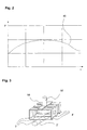
- the one required for cutting through the metal bolt Cutting force (F) is measured and recorded as a function of time (t) (Fig. 2).
- the Curve 45 of the cutting force shows an arcuate course, the cutting force (F) in the center of the metal bolt is maximum.
- the curve shape obtained is due to the fact that the measured cutting force (F) not only from the strength of the metal bolt on the cutting line, but also dependent on the active wire length, i.e. the length of the cutting line , in this example the cutting force is dominated by the influence of the active wire length which reaches a maximum in the middle of the metal bolt.
- FIG. 4 shows the temperature distribution simulated by means of a computing model, one of the given ones Heating parameters of preheated thixotropic metal bolt 41 made of aluminum (AlMgSi7) with a diameter of around 102 mm.
- the metal bolt 41 is in one Bolt recipients 42 made of steel.
- the bolt section with the brightest area fill on the upper edge of the metal pin shows the zone of greatest heating with a temperature from around 595 ° C.
- the temperature decreases Zones with darkening area filling gradually decrease and reach a minimum in "cold core" 43 of the metal bolt with a temperature value of around 580 ° C, which is represented by a black fill. From Fig. 4, the advanced Cooling of the metal bolt removed from its contact surface with the recipient 42 become.
- Metal bolt is made in a cross section transverse to the method according to the invention its longitudinal direction examined for strength (Fig. 5). To do this, the speed curve 31 of the cutting wire and the course of the cutting force 32 are recorded, where “v” is the cutting wire speed and "F” the cutting force and "S” the equivalent Shear stress and "t” mean time.
- the one from this data and other fixed Characteristic-calculated course of the "equivalent shear stress” 33 shows at the beginning of Record a striking decrease (a) in shear stress, which is due to the so-called “Skin effect" is to be attributed, that is, the cutting wire pierces with increased Force the surface of the metal bolt.
- the curve section (d) with high shear stresses reflects the firmer, cooler core 43 of the metal bolt 41 (see Fig. 4).
- the measuring range (d) of high shear stresses is shifted towards the end of the measurement and therefore does not occur when crossing the center of the metal bolt.
Landscapes
- Immunology (AREA)
- Pathology (AREA)
- Life Sciences & Earth Sciences (AREA)
- Chemical & Material Sciences (AREA)
- Analytical Chemistry (AREA)
- Biochemistry (AREA)
- General Health & Medical Sciences (AREA)
- General Physics & Mathematics (AREA)
- Health & Medical Sciences (AREA)
- Engineering & Computer Science (AREA)
- Physics & Mathematics (AREA)
- Mechanical Engineering (AREA)
- Investigating Or Analyzing Materials Using Thermal Means (AREA)
- Investigating Strength Of Materials By Application Of Mechanical Stress (AREA)
- Investigating Or Analyzing Non-Biological Materials By The Use Of Chemical Means (AREA)
- Electric Connection Of Electric Components To Printed Circuits (AREA)
- Manufacture Of Motors, Generators (AREA)
Description

- Fig. 1:
- Schematische Darstellung einer erfindungsgemässen Messvorrichtung;
- Fig. 2:
- Schematische Darstellung der aufzuwendenden Schneidkraft durch einen vorgewärmten Metallbolzen mit homogener Verteilung des Metallflüssiganteils;
- Fig. 3:
- Ausschnitt einer Messvorrichtung zur Ermittlung der Festigkeit thixotroper Metallbolzen mit drei Schneiddrähten;
- Fig. 4:
- Simulation der Temperaturverteilung durch den Querschnitt eines vorgewärmten, thixotropen Metallbolzens;
- Fig. 5:
- Graphische Darstellung des Verlaufes von Geschwindigkeit v, Schneidkraft F, und äquivalenter Scherkraft S durch den Querschnitt des vorgewärmten thixotropen Metallbolzens gemäss Fig. 4.
Claims (16)
- Messvorrichtung (1) zur Bestimmung des Festigkeitszustandes und/oder des Metallflüssiganteils eines vorgewärmten Metallkörpers (2) mit thixotropen Eigenschaften,
dadurch gekennzeichnet, dass
die Messvorrichtung (1) einen oder mehrere in Abstand zueinander angeordnete Schneiddrähte (5) zum Durchschneiden des thixotropen Metallkörpers (2) enthält und ein Antrieb (6) zur Fortbewegung des Schneiddrahtes (5) und zum Durchschneiden des Metallkörpers (2) mit dem Schneiddraht (5) und Mittel (8) zur Bestimmung der vom Antrieb (6) auf den Schneiddraht (5) ausgeübten Schneidkraft und zur Bestimmung der Geschwindigkeit des Schneiddrahtes (5) vorgesehen sind. - Messvorrichtung nach Anspruch 1, dadurch gekennzeichnet, dass der Schneiddraht (5) zwischen zwei Gabelbeinen (20) eines gabelförmigen Rahmens (4) mit einem die Gabelbeine (20) verbindenden Verbindungsteil (14) eingespannt ist und der gabelförmige Rahmen (4) an einem durch den Antrieb (6) angetriebenen Vortriebselement (18) befestigt ist und der Schneiddraht quer, vorzugsweise um 90° quer, zur Längsrichtung des Metallkörpers (2) angeordnet ist.
- Messvorrichtung nach einem der Ansprüche 1 bis 2, dadurch gekennzeichnet, dass die Messvorrichtung (1) mehrere, vorzugsweise drei, quer zur Längsrichtung des Metallkörpers (2') parallel und vorzugsweise in gleichmässigem Abstand zueinander liegende, gabelförmige Rahmen (4') mit einem Schneiddraht (5') enthält und die gabelförmigen Rahmen (4') an ein gemeinsames Vortriebselement (18') angebracht sind und von einem gemeinsamen Antrieb bewegt sind.
- Messvorrichtung nach einem der Ansprüche 1 bis 3, dadurch gekennzeichnet, dass der Metallkörper ein zylinderförmiger Metallbolzen (2) ist und eine wannenförmige Bolzenhalterung (3) zur Aufnahme und stabilen Lagerung des Metallbolzens (2) vorgesehen ist und die Bolzenhalterung (3) durchgehende Spaltöffnungen zum Durchführen des Schneiddrahtes (5) enthält.
- Messvorrichtung nach einem der Ansprüche 1 bis 4, dadurch gekennzeichnet, dass die Messvorrichtung (1) eine Lastzelle (8), vorzugsweise ein auf dem piezoelektrischen Prinzip arbeitender Drucksensor, zur Erfassung der auf den Schneiddraht ausgeübten Schneidkraft enthält und die Lastzelle (8) bevorzugt zwischen dem Verbindungsteil (14) und dem Vortriebselement (18) angeordnet ist.
- Messvorrichtung nach einem der Ansprüche 1 bis 5, dadurch gekennzeichnet, dass die Messvorrichtung (1) zur Ermittlung der Schneiddrahtgeschwindigkeit einen Positionstaster (7) zur kontinuierlichen Erfassung der Position des Messdrahtes (5) oder eines mitbewegten Vorrichtungsteils in Abhängigkeit der Zeit enthält.
- Messvorrichtung nach einem der Ansprüche 1 bis 6, dadurch gekennzeichnet, dass ein oder mehrere Thermoelemente (9), vorzugsweise Mantelthermoelemente zur Erfassung der Temperaturverteilung durch den Bolzenquerschnitt mit ihren thermowirksamen Verbindungsstellen punktweise am aktiven Schneiddraht (5) angebracht sind und die Thermodrähte (9a) über eine Vergleichsstelle mit einer elektronischen Auswerteschaltung (9b) verbunden sind.
- Messvorrichtung nach Anspruch 7, dadurch gekennzeichnet, dass die thermowirksamen Verbindungsstellen der Thermodrähte (9) gelötet, geschweisst oder gequetscht sind und die Thermoelemente (9) mit ihren thermowirksamen Verbindungsstellen an den Schneiddraht (5) befestigt, insbesondere gelötet oder geschweisst sind, und die Thermodrähte (9a) entgegen der Schneidrichtung im Metallkörper (2) vom Schneiddraht (5) wegführen sind.
- Messvorrichtung nach einem der Ansprüche 1 bis 8, dadurch gekennzeichnet, dass die Messvorrichtung (1) die Lastzelle (8), der Positionstaster (7) und die Thermolemente (9) über Datenleitungen (13a-c) mit einer Datenerfassungs-, Steuer- und Auswerteinheit (12) verbunden sind und Ein- und Ausgabegeräte (21, 22) über Datenleitungen (13e-f) mit der Datenerfassungs-, Steuer- und Auswerteinheit (12) verbunden sind.
- Messvorrichtung nach einem der Ansprüche 1 bis 9, dadurch gekennzeichnet, dass die Bolzenhalterung (3) auf einem Wagen (10) angebracht ist und der Wagen (10) horizontal beweglich gelagert ist und zum Ein- und Wegführen des Metallkörpers (2) aus der Messvorrichtung (1) gefahren werden kann.
- Verfahren zur Bestimmung des Zustandes eines vorgewärmten Metallkörpers (2) mit thixotropen Eigenschaften mittels einer Messvorrichtung (1) gemäss Anspruch 1,
dadurch gekennzeichnet, dass
ein oder mehrere quer zur Längsrichtung des Metallkörpers (2) in Abstand zueinander parallel angeordnete Schneiddrähte (5) durch einen oder mehrere Querschnitte am thixotropen Metallkörper (2) unter Durchschneiden desselben vorgetrieben werden und die aufzuwendende Schneidkraft des einzelnen Schneiddrahtes (5) sowie die Geschwindigkeit des Schneiddrahtes (5) kontinuierlich über den gesamten Querschnitt in Abhängigkeit der Position des Schneiddrahtes im Metallkörper erfasst wird und unter Einbezug der gemessenen Schneidkraft, Geschwindigkeit und Position des Schneiddrahtes und der geometrischen Beschaffenheit des Schneiddrahtes und des thixotropen Metallkörpers (2) sowie der Länge des aktiven Schneiddrahtes eine die Festigkeit innerhalb des thixotropen Metallkörpers (2) am durchschnittenen Querschnitt wiedergebende Kenngrösse rechnerisch ermittelt wird. - Verfahren nach Anspruch 11, dadurch gekennzeichnet, dass der oder die Schneiddrähte (5) mit gleichmässiger Grundgeschwindigkeit durch den oder die Querschnitte des thixotropen Metallkörpers (2) geführt werden.
- Verfahren nach einem der Ansprüche 11 bis 13, dadurch gekennzeichnet, dass die Festigkeit durch die Berechnung einer äquivalenten Scherspannung τ vo beschrieben wird und die äquivalente Scherspannung τ vo aus der äquivalenten Schneidkraft F v0, dem Drahtdurchmesser dw , und der aktiven Länge es Schneiddrahtes lw mit der Näherungsgleichung:berechnet wird, wobei die äquivalente Schneidkraft F v0 mit der Näherungsgleichung
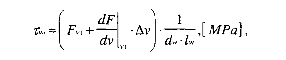 berechnet wird.
- Verfahren nach einem der Ansprüche 11 bis 13, dadurch gekennzeichnet, dass während des Messvorganges zur Ermittlung der Schneidkraft über einen oder mehrere, bevorzugt gleichmässig angeordnete Abschnitte entlang des aktiven Schneiddrahtes kontinuierlich die Temperatur mittels an den Schneiddraht angebrachten Thermoelementen ermittelt wird und aus der ermittelten Temperaturverteilung im thixotropen Metallkörper die Verteilung des Metallflüssiganteils bestimmt wird.
- Verfahren nach Anspruch 14, dadurch gekennzeichnet, dass mittels Auswerteinheit (12) aus der Schneidkraft die äquivalente Scherspannung τ v o oder relative dynamische Viskosität ηrel bestimmt wird und die ermittelte Verteilung des Metallflüssiganteils in eine Beziehung zur äquivalenten Scherspannung oder relativen dynamischen Viskosität gesetzt wird.
- Verfahren nach einem der Ansprüche 11 bis 15, dadurch gekennzeichnet, dass der thixotrope Metallkörper ein zylinderförmiger Bolzen ist und mehrere Schneiddrähte quer zur Längsrichtung des Bolzens gleichzeitig an mehreren, vorzugsweise in gleichmässigem Abstand zueinander liegenden, Stellen mit gleichmässiger Grundgeschwindigkeit des Schneiddrahtes durch den Bolzenquerschnitt geführt werden und mittels Interpolation die Festigkeit und/oder die Temperatur innerhalb des Bolzens in dreidimensionaler Form rechnerisch ermittelt wird.
Priority Applications (1)
| Application Number | Priority Date | Filing Date | Title |
|---|---|---|---|
| EP01925410A EP1269148B1 (de) | 2000-03-22 | 2001-03-09 | Bestimmung des festigkeitszustandes eines vorgewärmten metallkörpers mit thixotropen eigenschaften |
Applications Claiming Priority (4)
| Application Number | Priority Date | Filing Date | Title |
|---|---|---|---|
| EP00810247A EP1136809A1 (de) | 2000-03-22 | 2000-03-22 | Bestimmung des Festigkeitszustandes eines vorgewärmten Metallköpers mit thixotropen Eigenschaften |
| EP00810247 | 2000-03-22 | ||
| EP01925410A EP1269148B1 (de) | 2000-03-22 | 2001-03-09 | Bestimmung des festigkeitszustandes eines vorgewärmten metallkörpers mit thixotropen eigenschaften |
| PCT/EP2001/002666 WO2001071313A1 (de) | 2000-03-22 | 2001-03-09 | Bestimmung des festigkeitszustandes eines vorgewärmten metallkörpers mit thixotropen eigenschaften |
Publications (2)
| Publication Number | Publication Date |
|---|---|
| EP1269148A1 EP1269148A1 (de) | 2003-01-02 |
| EP1269148B1 true EP1269148B1 (de) | 2003-10-29 |
Family
ID=8174613
Family Applications (2)
| Application Number | Title | Priority Date | Filing Date |
|---|---|---|---|
| EP00810247A Withdrawn EP1136809A1 (de) | 2000-03-22 | 2000-03-22 | Bestimmung des Festigkeitszustandes eines vorgewärmten Metallköpers mit thixotropen Eigenschaften |
| EP01925410A Expired - Lifetime EP1269148B1 (de) | 2000-03-22 | 2001-03-09 | Bestimmung des festigkeitszustandes eines vorgewärmten metallkörpers mit thixotropen eigenschaften |
Family Applications Before (1)
| Application Number | Title | Priority Date | Filing Date |
|---|---|---|---|
| EP00810247A Withdrawn EP1136809A1 (de) | 2000-03-22 | 2000-03-22 | Bestimmung des Festigkeitszustandes eines vorgewärmten Metallköpers mit thixotropen Eigenschaften |
Country Status (6)
| Country | Link |
|---|---|
| EP (2) | EP1136809A1 (de) |
| AT (1) | ATE253217T1 (de) |
| AU (1) | AU2001252177A1 (de) |
| DE (1) | DE50100878D1 (de) |
| ES (1) | ES2208589T3 (de) |
| WO (1) | WO2001071313A1 (de) |
Families Citing this family (7)
| Publication number | Priority date | Publication date | Assignee | Title |
|---|---|---|---|---|
| RU2370345C1 (ru) * | 2008-01-09 | 2009-10-20 | Государственное образовательное учреждение высшего профессионального образования Волгоградский государственный технический университет (ВолгГТУ) | Способ определения допустимой скорости резания в условиях многоинструментальной настройки |
| CN102049579B (zh) * | 2009-10-28 | 2012-06-20 | 上海日进机床有限公司 | 具有立柱式机架的金刚线截断机 |
| JP5271393B2 (ja) * | 2011-07-20 | 2013-08-21 | 三星ダイヤモンド工業株式会社 | レーザスクライブ装置 |
| FR3043773B1 (fr) * | 2015-11-17 | 2019-03-29 | Institut National Des Sciences Appliquees De Lyon | Systeme de controle du serrage d’un assemblage boulonne (101), l’assemblage boulonne, dispositif de bridage et procede de controle associes. |
| CN108214953B (zh) * | 2018-01-19 | 2019-10-22 | 郑灵芝 | 高强度脆性材料加工方法 |
| CN109596333B (zh) * | 2019-01-14 | 2020-07-28 | 湘潭大学 | 一种数控热缩刀杆装刀疲劳试验装置 |
| CN113029751B (zh) * | 2021-03-11 | 2022-12-16 | 天津大学 | 一种用于铅铋环境下的原位力学试验装置 |
Family Cites Families (3)
| Publication number | Priority date | Publication date | Assignee | Title |
|---|---|---|---|---|
| US4164140A (en) * | 1978-01-30 | 1979-08-14 | Phillips Petroleum Company | Method and apparatus for measuring material properties related to strength |
| JP3566449B2 (ja) * | 1996-03-27 | 2004-09-15 | 信越半導体株式会社 | ワイヤソーによるワーク切断方法 |
| GB2337822B (en) * | 1998-05-26 | 2002-04-24 | Univ Sheffield | Material characterisation |
-
2000
- 2000-03-22 EP EP00810247A patent/EP1136809A1/de not_active Withdrawn
-
2001
- 2001-03-09 DE DE50100878T patent/DE50100878D1/de not_active Expired - Fee Related
- 2001-03-09 EP EP01925410A patent/EP1269148B1/de not_active Expired - Lifetime
- 2001-03-09 AU AU2001252177A patent/AU2001252177A1/en not_active Abandoned
- 2001-03-09 ES ES01925410T patent/ES2208589T3/es not_active Expired - Lifetime
- 2001-03-09 WO PCT/EP2001/002666 patent/WO2001071313A1/de not_active Ceased
- 2001-03-09 AT AT01925410T patent/ATE253217T1/de not_active IP Right Cessation
Also Published As
| Publication number | Publication date |
|---|---|
| AU2001252177A1 (en) | 2001-10-03 |
| WO2001071313A1 (de) | 2001-09-27 |
| EP1136809A1 (de) | 2001-09-26 |
| EP1269148A1 (de) | 2003-01-02 |
| ATE253217T1 (de) | 2003-11-15 |
| DE50100878D1 (de) | 2003-12-04 |
| ES2208589T3 (es) | 2004-06-16 |
Similar Documents
| Publication | Publication Date | Title |
|---|---|---|
| DE60034322T2 (de) | Verfahren zum schätzen des schmelzflussmusters beim strangguss | |
| EP2238805B1 (de) | Verfahren zur ermittlung eines strahlungsmasses für eine thermische strahlung, lichtbogenofen, eine signalverarbeitungseinrichtung sowie programmcode und ein speichermedium zur durchführung des verfahrens | |
| EP2910922B1 (de) | Vorrichtung und Verfahren zur Messung einer Längenänderung einer Probe und/oder zur Messung einer Deformationskraft an einer Probe | |
| DE102007003426A1 (de) | Verfahren zur Gefrierpunkttemperaturmessung und zur Temperaturkalibrierung bei der Differentialrasterhalorimetrie | |
| DE10331125B3 (de) | Verfahren zum Abgleichen und Messen in Schmelzen mittels optischer Fasern sowie Vorrichtung dazu und deren Verwendung | |
| EP1136809A1 (de) | Bestimmung des Festigkeitszustandes eines vorgewärmten Metallköpers mit thixotropen Eigenschaften | |
| EP3112854B1 (de) | Verfahren und vorrichtung zur thermomechanischen analyse einer probe | |
| EP2965070B1 (de) | Verfahren und vorrichtung zur materialanalyse | |
| DE3033164A1 (de) | Verfahren zur ueberwachung der abnutzung der feuerfesten waende eines hochofens | |
| AT521529B1 (de) | Biegevorrichtung und Verfahren zur Ermittlung zumindest eines Materialparameters bzw. Bearbeitungsparameters für eine Werkstückbearbeitungsvorrichtung | |
| DE3542966A1 (de) | Verfahren und vorrichtung zum freiformschmieden von werkstuecken | |
| EP0715555B1 (de) | Verfahren zur ermittlung eines bewertungszeitintervalles sowie verfahren zur qualitätsbeurteilung einer punktschweissverbindung auf grundlage eines temperaturverlaufes in dem bewertungszeitintervall | |
| DE69808295T2 (de) | Verfahren und vorrichtung zur oberflächentemperaturkontrolle eines blockes während des giessens und insbesondere während des angiessens | |
| DE3417969A1 (de) | Verfahren zum betreiben einer kontinuierlichen bandgiessanlage | |
| EP3765831B1 (de) | System zum erfassen einer mechanischen zug-/druckspannung einer schiene | |
| DE69820055T2 (de) | Apparat und methode für das messen der temperatur einer sich bewegenden oberfläche | |
| DE19981496B3 (de) | Thixo-Giessmaterial aus einer Legierung auf Fe-Basis und Verfahren zum Erwärmen desselben | |
| DE102015122889B3 (de) | Verfahren und Messanordnung zum Bestimmen der Zugfestigkeit eines geschweißten Werkstoffs | |
| DE2631199C3 (de) | Vorrichtung zum Messen von Dehnungen | |
| Onawola et al. | Warm compression and extrusion tests of aluminium | |
| EP1195595A1 (de) | Temperiervorrichtung, insbesondere für eine Werkstoffprüfvorrichtung sowie Werkstoffprüfverfahren | |
| EP0447858B1 (de) | Verfahren zur Erzeugung von längsgerichteten grobkörnigen Stengelkristallen in einem aus einer oxyddispersionsgehärteten Nickelbasis-Superlegierung bestehenden Werkstück | |
| DE3428657C2 (de) | ||
| DE2545162A1 (de) | Verfahren und vorrichtung zum regeln von elektroschlackenumschmelzverfahren fuer metalle | |
| DE2147297C3 (de) | Verfahren und Vorrichtung zur Feststellung des Werkstoffverhaltens eines nach einem metallurgischen Verfahren herstellbaren Werkstoffes zur Optimierung bestimmter Materialeigenschatten |
Legal Events
| Date | Code | Title | Description |
|---|---|---|---|
| PUAI | Public reference made under article 153(3) epc to a published international application that has entered the european phase |
Free format text: ORIGINAL CODE: 0009012 |
|
| 17P | Request for examination filed |
Effective date: 20021022 |
|
| AK | Designated contracting states |
Kind code of ref document: A1 Designated state(s): AT BE CH CY DE DK ES FI FR GB GR IE IT LI LU MC NL PT SE TR |
|
| RIN1 | Information on inventor provided before grant (corrected) |
Inventor name: BAGNOUD, CHRISTOPHE Inventor name: ARNOLD, GREGOIRE Inventor name: PLATA, MIROSLAW |
|
| GRAH | Despatch of communication of intention to grant a patent |
Free format text: ORIGINAL CODE: EPIDOS IGRA |
|
| GRAS | Grant fee paid |
Free format text: ORIGINAL CODE: EPIDOSNIGR3 |
|
| GRAA | (expected) grant |
Free format text: ORIGINAL CODE: 0009210 |
|
| AK | Designated contracting states |
Kind code of ref document: B1 Designated state(s): AT BE CH DE ES FR GB GR IT LI LU NL SE |
|
| REG | Reference to a national code |
Ref country code: GB Ref legal event code: FG4D Free format text: NOT ENGLISH |
|
| REG | Reference to a national code |
Ref country code: CH Ref legal event code: EP |
|
| GBT | Gb: translation of ep patent filed (gb section 77(6)(a)/1977) |
Effective date: 20031029 |
|
| REG | Reference to a national code |
Ref country code: IE Ref legal event code: FG4D Free format text: GERMAN |
|
| REF | Corresponds to: |
Ref document number: 50100878 Country of ref document: DE Date of ref document: 20031204 Kind code of ref document: P |
|
| PG25 | Lapsed in a contracting state [announced via postgrant information from national office to epo] |
Ref country code: GR Free format text: LAPSE BECAUSE OF FAILURE TO SUBMIT A TRANSLATION OF THE DESCRIPTION OR TO PAY THE FEE WITHIN THE PRESCRIBED TIME-LIMIT Effective date: 20040129 |
|
| REG | Reference to a national code |
Ref country code: SE Ref legal event code: TRGR |
|
| PG25 | Lapsed in a contracting state [announced via postgrant information from national office to epo] |
Ref country code: LU Free format text: LAPSE BECAUSE OF NON-PAYMENT OF DUE FEES Effective date: 20040309 Ref country code: AT Free format text: LAPSE BECAUSE OF NON-PAYMENT OF DUE FEES Effective date: 20040309 |
|
| PG25 | Lapsed in a contracting state [announced via postgrant information from national office to epo] |
Ref country code: SE Free format text: LAPSE BECAUSE OF NON-PAYMENT OF DUE FEES Effective date: 20040310 Ref country code: ES Free format text: LAPSE BECAUSE OF NON-PAYMENT OF DUE FEES Effective date: 20040310 |
|
| PG25 | Lapsed in a contracting state [announced via postgrant information from national office to epo] |
Ref country code: BE Free format text: LAPSE BECAUSE OF NON-PAYMENT OF DUE FEES Effective date: 20040331 |
|
| REG | Reference to a national code |
Ref country code: ES Ref legal event code: FG2A Ref document number: 2208589 Country of ref document: ES Kind code of ref document: T3 |
|
| REG | Reference to a national code |
Ref country code: IE Ref legal event code: FD4D |
|
| ET | Fr: translation filed | ||
| PLBE | No opposition filed within time limit |
Free format text: ORIGINAL CODE: 0009261 |
|
| STAA | Information on the status of an ep patent application or granted ep patent |
Free format text: STATUS: NO OPPOSITION FILED WITHIN TIME LIMIT |
|
| BERE | Be: lapsed |
Owner name: *ALCAN TECHNOLOGY & MANAGEMENT LTD Effective date: 20040331 |
|
| PG25 | Lapsed in a contracting state [announced via postgrant information from national office to epo] |
Ref country code: DE Free format text: LAPSE BECAUSE OF NON-PAYMENT OF DUE FEES Effective date: 20041001 |
|
| 26N | No opposition filed |
Effective date: 20040730 |
|
| EUG | Se: european patent has lapsed | ||
| PG25 | Lapsed in a contracting state [announced via postgrant information from national office to epo] |
Ref country code: IT Free format text: LAPSE BECAUSE OF NON-PAYMENT OF DUE FEES Effective date: 20050309 Ref country code: GB Free format text: LAPSE BECAUSE OF NON-PAYMENT OF DUE FEES Effective date: 20050309 |
|
| PG25 | Lapsed in a contracting state [announced via postgrant information from national office to epo] |
Ref country code: LI Free format text: LAPSE BECAUSE OF NON-PAYMENT OF DUE FEES Effective date: 20050331 Ref country code: CH Free format text: LAPSE BECAUSE OF NON-PAYMENT OF DUE FEES Effective date: 20050331 |
|
| REG | Reference to a national code |
Ref country code: ES Ref legal event code: FD2A Effective date: 20040310 |
|
| PG25 | Lapsed in a contracting state [announced via postgrant information from national office to epo] |
Ref country code: NL Free format text: LAPSE BECAUSE OF NON-PAYMENT OF DUE FEES Effective date: 20051001 |
|
| REG | Reference to a national code |
Ref country code: CH Ref legal event code: PL |
|
| GBPC | Gb: european patent ceased through non-payment of renewal fee |
Effective date: 20050309 |
|
| NLV4 | Nl: lapsed or anulled due to non-payment of the annual fee |
Effective date: 20051001 |
|
| PG25 | Lapsed in a contracting state [announced via postgrant information from national office to epo] |
Ref country code: FR Free format text: LAPSE BECAUSE OF NON-PAYMENT OF DUE FEES Effective date: 20040331 |
|
| REG | Reference to a national code |
Ref country code: FR Ref legal event code: ST Effective date: 20110531 |