EP1268944B1 - Method for securing sheet piles - Google Patents
Method for securing sheet piles Download PDFInfo
- Publication number
- EP1268944B1 EP1268944B1 EP01915379A EP01915379A EP1268944B1 EP 1268944 B1 EP1268944 B1 EP 1268944B1 EP 01915379 A EP01915379 A EP 01915379A EP 01915379 A EP01915379 A EP 01915379A EP 1268944 B1 EP1268944 B1 EP 1268944B1
- Authority
- EP
- European Patent Office
- Prior art keywords
- sheet pile
- interlock
- electrode
- chamber
- axial groove
- Prior art date
- Legal status (The legal status is an assumption and is not a legal conclusion. Google has not performed a legal analysis and makes no representation as to the accuracy of the status listed.)
- Expired - Lifetime
Links
Images


Classifications
-
- E—FIXED CONSTRUCTIONS
- E02—HYDRAULIC ENGINEERING; FOUNDATIONS; SOIL SHIFTING
- E02D—FOUNDATIONS; EXCAVATIONS; EMBANKMENTS; UNDERGROUND OR UNDERWATER STRUCTURES
- E02D5/00—Bulkheads, piles, or other structural elements specially adapted to foundation engineering
- E02D5/02—Sheet piles or sheet pile bulkheads
- E02D5/03—Prefabricated parts, e.g. composite sheet piles
- E02D5/04—Prefabricated parts, e.g. composite sheet piles made of steel
- E02D5/08—Locking forms; Edge joints; Pile crossings; Branch pieces
-
- E—FIXED CONSTRUCTIONS
- E02—HYDRAULIC ENGINEERING; FOUNDATIONS; SOIL SHIFTING
- E02D—FOUNDATIONS; EXCAVATIONS; EMBANKMENTS; UNDERGROUND OR UNDERWATER STRUCTURES
- E02D5/00—Bulkheads, piles, or other structural elements specially adapted to foundation engineering
- E02D5/02—Sheet piles or sheet pile bulkheads
- E02D5/14—Sealing joints between adjacent sheet piles
Definitions
- the present invention relates to a method for securing two sheet piles interlocked by means of sheet pile interlocks.
- sheet piles for constructing retaining walls are well known.
- the sheet piles used in such walls have sheet pile interlocks along their longitudinal edges, which can be interlocked so as to maintain the longitudinal edges of adjacent sheet piles interconnected with each other.
- Current sheet pile interlocks of the double-hook interlock type (type 1 according to EN10248 norm), as e.g. LARSSEN type sheet pile interlocks, are hook shaped elements with an internal interlock chamber.
- a sheet pile wall is formed by driving a first sheet pile into the ground, introducing the bottom end of the trailing sheet pile interlock of a second sheet pile with the top end of the leading sheet pile interlock of the first sheet pile, driving the second sheet pile into the ground, and then repeating the process to insert third, fourth etc sheet piles into the wall.
- two interconnected sheet piles can be secured by pressing impressions on the outer connection joint between the two interlocked sheet pile interlocks.
- the pressing of these impressions are effected by means of a punch adapted to be operated by a hydraulic percussion hammer.
- the securing of interconnected sheet piles by pressing impressions is e.g. used for combining sheet piles into double or triple sheets, also known as driving units, prior to driving them into the ground.
- driving units also known as driving units
- the welding seam can only be made on the top half, often only the top third of the sheet pile interlocks, as the remaining part of the sheet pile wall is still not accessible.
- the remaining part of the sheet pile wall can hence not be rendered waterproof.
- the technical problem underlying the present invention is to provide a reliable method for firmly securing sheet pile interlocks against longitudinal shifting relative to one another, even if the sheet pile interlocks are not accessible. This problem is solved by a method as claimed in claim 1.
- a welding electrode is axially inserted into an axial groove between the sheet pile interlocks, which are then welded together in the groove.
- the sheet pile interlocks need not be accessible from the outside in order to make a welding. It follows that sheet piles or driving units can now also be secured after having been driven into the ground. This is of particular advantage in case excavation is to take place as the sheet piles or driving units can be secured beforehand. The sheet pile interlocks can hence not shift and the sheet pile wall cannot deform during the excavation process.
- a method in accordance with the invention is particularly advantageous if the interlocked sheet pile interlocks are at least partially located below ground level.
- the welding electrode can then be axially introduced through the axial groove below ground level and the sheet pile interlocks can be welded together below ground level.
- the method hence allows firmly securing two sheet piles or driving units, after they are driven into the ground.
- the welding operation allows to provide a bond with a higher shearing strength than a bond achieved by injecting a curing mass, and that the welding operation is far less affected by ground material and/or water penetrating the interlock chamber than a curing operation.
- a continuous welding seam can be made along the whole length of the axial groove, whereby the sheet pile wall can be rendered waterproof along the whole of its height.
- the welding electrode is connected to a conductor, which is preferably a semi-rigid conductor, e.g. an electrically insulated copper conductor, so that it can be used to push the welding electrode far down into the axial groove.
- a conductor which is preferably a semi-rigid conductor, e.g. an electrically insulated copper conductor, so that it can be used to push the welding electrode far down into the axial groove.
- the welding electrode is axially introduced into the axial groove up to a first depth, where a first welding is made. The welding electrode is then drawn back to a second depth; where a second welding is made. This discontinuous welding allows for time saving securing operation.
- the welding electrode is axially introduced into the axial groove up to a first depth, where the welding electrode is consumed by making a welding.
- the conductor is then withdrawn from the groove and connected to a new welding electrode, which is then axially introduced into the axial groove up to a second depth, where it is consumed by making another welding.
- the second depth can for example correspond to the end of the first welding, so that a continuous welding seam is obtained. This continuous welding provides a sealed connection between two sheet piles.
- a fluxed electrode facilitates arc ignition and stability during welding. It also allows welding to take place under water and it can be easily used on site with conventional welding generators.
- the fluxed electrode also has the particular advantage that it allows for a discontinuous welding, i.e. local weldings can be made at different depths in the axial groove.
- a straightener can be used for introducing the semi-rigid conductor with the welding electrode into the groove. It straightens the semi-rigid conductor and pushes it down the axial groove. It can further be used to pull the conductor back out of the axial groove.
- the first sheet pile When constructing a sheet pile wall, the first sheet pile is first driven into the ground.
- the leading sheet pile interlock of the first sheet pile has an interlock chamber protected from ground material.
- An interlock head of a trailing sheet pile interlock of a second sheet pile is engaged in the interlock chamber when the second sheet pile is driven into the ground.
- the interlock head preferably has an axial groove facing a wall of the interlock chamber for receiving the welding electrode.
- the interlock chamber can have a substantially right angle comer.
- the interlock head engaging the interlock chamber preferably has a cross-section that is complementary to the cross-section of the interlock chamber, and the axial groove is located at the thickest part of the interlock head and facing the right angle comer of the interlock chamber.
- the interlock chamber can further comprise a sealant arranged at least along part of its walls for sealing, and hence rendering water proof the connection joint between two sheet piles.
- an obturating device comprising an inflatable tube is inserted into the interlock chamber of the sheet pile interlock to be protected. Once the obturating device is in place within the interlock chamber, its inflatable tube is inflated, so that the obturating device effectively closes the opening to the interlock chamber. It follows that no ground material can enter the interlock chamber while the sheet pile is being driven into the ground. Once the sheet pile is in place, the inflatable tube is again deflated, and the obturating device can be easily withdrawn from the interlock chamber.
- the obturating device ensures excellent protection for the interlock chamber against ground material, and while the inflatable tube is deflated, the obturating device can be easily inserted into or retracted from the interlock chamber.
- the obturating device can further comprise a flexible tube with an open front end alongside the inflatable tube which has a closed front end.
- This flexible tube can then be used for filling the interlock chamber with sand or synthetic foam (as e.g. a PU foam) while the obturating device is withdrawn from the interlock chamber.
- sand or synthetic foam as e.g. a PU foam
- the flexible tube it is not excluded to conceive the flexible tube as a separate piece, but it is preferred to firmly attach it to the inflatable tube and, in particular, to form it in one piece with the inflatable tube.
- inflation of the inflatable tube pushes an obturating block into the longitudinal opening of the interlock chamber.
- This obturating block closes the longitudinal opening of the interlock chamber.
- the obturating block can be made stronger than the inflatable tube and is hence less likely to be damaged during the driving process. It is preferably a semi-rigid body, because such a semi-rigid body may be more easily introduced in and withdrawn from the interlock chamber. Furthermore, it is preferably a wedge shaped body engaging the longitudinal opening of the interlock chamber.
- the wedge shape ensures that, when the inflatable tube is inflated, the obturating block centres itself in the longitudinal opening of the interlock chamber so as to effectively obturate this opening from the inside of the interlock chamber. It is not excluded to conceive the obturating block as a separate piece, but it is preferred to firmly attach it to the inflatable tube and, in particular, to form it in one piece with the inflatable tube. The fact that the inflatable tube and obturating block are firmly attached together allows for easy manipulation on the building site.
- the obturating device when constructing a sheet pile wall, the obturating device is inserted into the interlock chamber of the leading sheet pile interlock of a first sheet pile.
- the inflatable tube is inflated, e.g. by means of compressed air, and this first sheet pile is driven into the ground.
- the inflatable tube is deflated and the obturating device is withdrawn from the interlock chamber. It will be appreciated that the withdrawn obturating device leaves an interlock chamber in the leading sheet pile interlock that is perfectly clean, i.e. free from any ground material.
- the obturating device is then inserted into the interlock chamber of the leading sheet pile interlock of a second sheet pile and the inflatable tube is inflated.
- the front end obturator Before driving a sheet pile into the ground, it is recommended to insert a front end obturator in the bottom end of the interlock chamber of a leading sheet pile interlock.
- the front end obturator displaces ground material from under the axial opening of the interlock chamber and prevents ground material from axially entering the interlock chamber.
- the front end obturator can e.g. be a simple bolt.
- the front end obturator advantageously has a conical head.
- the front end obturator is preferably just inserted into the interlock chamber, rather than fixed to the sheet pile, so that the front end obturator can simply be pushed out of the interlock chamber of the leading sheet pile interlock by the trailing sheet pile interlock of the subsequent sheet pile. This is of particular interest in case a sheet pile needs to be driven deeper into the ground than the preceding one.
- a short cleaning piece is preferably engaged with the leading sheet pile interlock of a first sheet pile before interconnecting this interlock with the trailing sheet pile interlock of a second sheet pile.
- the cleaning piece can e.g. be a piece of an interlocking sheet pile interlock, which removes any ground material from the inner walls of the leading sheet pile interlock and preferably wraps the outer walls of the leading sheet pile interlock, so that it also effectively removes any ground material from the outer walls of the leading sheet pile interlock.
- Fig.1 shows a sheet pile wall 10 in place in the ground.
- the sheet pile wall 10 is constructed with interlocked sheet piles 12, which each have a trailing 14 and a leading sheet pile interlock 16.
- Fig 2 and 3 show a section through the trailing sheet pile interlock 14 on its own, and interlocked with a leading sheet pile interlock 16 of an adjacent sheet pile respectively.
- Each hook-shaped sheet pile interlock 14, 16 comprises an interlock chamber 18 and an interlock head 20.
- the interlock head 20 of one sheet pile engages the interlock chamber 18 of the other sheet pile, the interlock chamber 18 and the interlock head 20 having complementary cross-sections.
- the thickest corner of the interlock head 20 of the trailing sheet pile interlock 14 comprises an axial groove 22.
- the interlock chamber 18 of the trailing sheet pile interlock 14 comprises a sealant 24 arranged at least along part of its walls.
- the axial groove 22 preferably has a diameter between 5 and 15 mm, ideally 8 mm, so as to receive a welding electrode.
- reference number 26 designates two interlocked sheet pile interlocks 14, 16.
- a straightener 31 is used to introduce a semi-rigid copper conductor 28, having a fluxed welding electrode 30 at its end, into the axial groove 22 arranged in the trailing sheet pile interlock 14.
- Conventional welding apparatus 32 can be used for operating the welding electrode 30.
- the welding electrode 30 is introduced into the axial groove 22 up to a first depth, where a first welding 33 is made. Once this first welding 33 is made, the welding electrode 30 is drawn back to a second depth, where a second welding 34 is then made. It will be appreciated that third, fourth, etc weldings can be made in the axial groove in the same way.
- the conductor 28 can be withdrawn from the axial groove 22 by means of the straightener 31.
- a new electrode 30 is attached to the conductor 28, which is then reintroduced into the axial groove 22 for making a further welding. If these weldings are created so close to each other that they touch, a continuous welding seam can be created in the axial groove 22.
- Fig.4 shows some sheet piles 12 horizontally placed on the ground at the work site.
- An obturating device 36 is inserted in the leading sheet pile interlock 16 and inflated by compressed air means 38.
- the obturating device 36 is described in more detail by referring to Fig.5 and 6, in which the obturating device 36 is arranged.
- the obturating device 36 comprises an inflatable tube 38 and a wedge shaped obturating block 40.
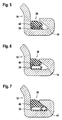
- Fig.5 and 6 show the inflatable tube 38 in its deflated and inflated state respectively.
- the obturating block 40 is firmly pressed in the longitudinal opening, which gives access to the interlock chamber 18. In other words, it blocks off this longitudinal opening of the interlock chamber 18, thereby preventing ground material from entering into the interlock chamber 18 through this opening.
- Fig.7 shows an obturating device 36 having a flexible tube 41 running alongside the inflatable tube 38.
- the flexible tube 41 has an open front end and is used to insert sand into the interlock chamber 18 when the obturating device 36 is being removed from the interlock chamber 18.
- the longitudinal opening of the interlock chamber 18 is thereby blocked off, whence preventing ground material from entering into the interlock chamber 18 through this opening.
- the preferred obturating device 36 shown in Fig.5 and 6 and in Fig.7 is a semi-rigid rubber piece. It may include synthetic or metallic reinforcement fibres or fabrics, which increase its tensile strength. Its surfaces coming into contact with the walls of the sheet pile interlock may receive a friction reducing coating.
- a front end obturator 42 is inserted in the bottom end of the interlock chamber 18.
- This front end obturator 42 which is shown in Fig.8 and 9, has a cylindrical body 44 and a conical head 46.
- a short cleaning piece 48 is engaged in the leading sheet pile interlock 16 of the first sheet pile for removing any ground material from the inner walls of the leading sheet pile interlock 16.
- the short cleaning piece 48 shown in Fig.1 wraps the outer walls of the leading sheet pile interlock 16 and has an acute front end. Consequently, when it is pushed down along the leading sheet pile interlock 16 by the trailing sheet pile interlock 14 of the second sheet pile, it effectively removes any ground material from the outer walls of the leading sheet pile interlock 16.
Abstract
Description
- Fig.1:
- is a perspective view of a sheet pile wall;
- Fig.2:
- is a section through a trailing sheet pile interlock;
- Fig.3
- is a section through a trailing sheet pile interlock interlocked with a leading sheet pile interlock;
- Fig.4
- is a perspective view of three sheet piles horizontally placed on the ground;
- Fig.5
- is a section through a deflated obturating device inside a sheet pile interlock;
- Fig.6
- is a section through an inflated obturating device inside a sheet pile interlock;
- Fig.7
- is a section through an inflated obturating device with flexible tube inside a sheet pile interlock;
- Fig.8
- is a perspective view of a front end obturator; and
- Fig.9
- is a schematic underneath view of the front end obturator of Fig.8.
Claims (16)
- A method for securing two sheet piles (12) interlocked by means of sheet pile interlocks (14, 16) characterised by:axially inserting an electrode (30) into an axial groove (22) between said sheet pile interlocks (14, 16) and welding said sheet pile interlocks (14, 16) together in said groove (22).
- Method according to claim 1, characterised in that said interlocked sheet pile interlocks (14, 16) are at least partially located below ground level, wherein said electrode (30) is axially introduced through said axial groove (22) below ground level and wherein said sheet pile interlocks (14, 16) are welded together below ground level.
- Method according to claim 1 or claim 2, characterised in that said electrode (30) is connected to a semi-rigid conductor (28).
- Method according to claims 1 to 3, characterised in that said electrode (30) is axially introduced into said axial groove (22) up to a first depth;
in that a first welding is made at said first depth;
in that said electrode (30) is drawn back to a second depth; and
in that a second welding is made at said second depth. - Method according to claims 1 to 3, characterised in that said electrode (30), which is connected to a conductor, is axially introduced into said axial groove (22) up to a first depth;
in that said electrode (30) consumed by making a first continuous welding starting at said first depth and pulling at said conductor;
in that said conductor is withdrawn from said axial groove (22) and connected to a new electrode (30);
in that said new electrode (30) is axially introduced into said axial groove (22) up to a second depth above said first depth; and
in that said new electrode (30) is consumed by making a second continuous welding starting at said second depth and pulling at said conductor. - Method according to claim 5, characterised in that said second depth corresponds to the end of said first welding, so that a continuous welding is obtained.
- Method according to any of the preceding claims, characterised in that said electrode (30) is a fluxed electrode.
- Method according to any of the preceding claims, characterised in that said electrode (30) is connected to a semi-rigid conductor (28) and in that a straightener (31) is used for inserting said electrode (30) into said axial groove (22).
- Method according to any of the preceding claims, characterised in that the first sheet pile (12) is first driven into the ground, wherein said first sheet pile (12) has a leading sheet pile interlock (16) with an interlock chamber (18) protected from ground material,
in that the second sheet pile (12) has a trailing sheet pile interlock (14) with an interlock head (20) engaged in said interlock chamber (18) when said second sheet pile (12) is driven into the ground; and
in that said interlock head (20) has an axial groove (22) facing a wall of said interlock chamber (18). - Method according to claim 9, characterised in that
said interlock chamber (18) has a substantially right angle corner;
said interlock head (20) engaging said interlock chamber (18) has a cross-section that is complementary to the cross-section of said interlock chamber (18), and
said axial groove (22) being located at the thickest part of said interlock head (20) and facing said right angle corner of said interlock chamber (18). - Method according to claim 9 or 10, characterised in that said interlock chamber (18) comprises a sealant (24).
- Method according to claim 9, 10 or 11, characterised in that the protection from ground material of said leading sheet pile interlock (16) comprises the following steps:inserting an obturating device (36) into said interlock chamber (18) of said leading sheet pile interlock (16), said obturating device (36) comprising an inflatable tube (38);inflating said inflatable tube (38);driving said sheet pile (12) into the ground;deflating said inflatable tube (38); andwithdrawing said obturating device (36) from said interlock chamber (18).
- Method according to claim 12, wherein said obturating device (36) comprises an obturating block (40), wherein inflation of said inflatable tube (38) pushes said obturating block (40) into the longitudinal opening of said interlock chamber (18).
- Method according to any of claims 12 or 13, characterised in that said obturating device (36) further comprises a flexible tube (35); and
in that while withdrawing said obturating device (36) from said interlock chamber (18), said interlock chamber (18) is filled with sand through said flexible tube (35). - Method according to any of claims 12 to 14, further characterised by:inserting a front end obturator (42) in the bottom end of said interlock chamber (18) of said leading sheet pile interlock (16) before driving said sheet pile (12) into the ground.
- Method according to any of claims 12 to 15, further characterised by:inserting a cleaning piece (48) into said leading sheet pile interlock (16) of said first sheet pile (12) before interlocking it with said trailing sheet pile interlock (14) of said second sheet pile (12).
Applications Claiming Priority (3)
| Application Number | Priority Date | Filing Date | Title |
|---|---|---|---|
| LU90558A LU90558B1 (en) | 2000-03-29 | 2000-03-29 | Method for securing sheet piles |
| LU90558 | 2000-03-29 | ||
| PCT/EP2001/003131 WO2001073210A1 (en) | 2000-03-29 | 2001-03-19 | Method for securing sheet piles |
Publications (2)
| Publication Number | Publication Date |
|---|---|
| EP1268944A1 EP1268944A1 (en) | 2003-01-02 |
| EP1268944B1 true EP1268944B1 (en) | 2004-05-19 |
Family
ID=19731885
Family Applications (1)
| Application Number | Title | Priority Date | Filing Date |
|---|---|---|---|
| EP01915379A Expired - Lifetime EP1268944B1 (en) | 2000-03-29 | 2001-03-19 | Method for securing sheet piles |
Country Status (11)
| Country | Link |
|---|---|
| US (1) | US6664509B2 (en) |
| EP (1) | EP1268944B1 (en) |
| JP (1) | JP2003529003A (en) |
| AT (1) | ATE267301T1 (en) |
| AU (1) | AU2001242488A1 (en) |
| CA (1) | CA2397708C (en) |
| DE (1) | DE60103388T2 (en) |
| LU (1) | LU90558B1 (en) |
| PL (1) | PL207289B1 (en) |
| RU (1) | RU2262572C2 (en) |
| WO (1) | WO2001073210A1 (en) |
Families Citing this family (9)
| Publication number | Priority date | Publication date | Assignee | Title |
|---|---|---|---|---|
| JP2005127053A (en) * | 2003-10-24 | 2005-05-19 | Giken Seisakusho Co Ltd | Z-shaped steel sheet pile press-fitting apparatus and z-shaped steel sheet pile press-fitting method |
| DE102005061721A1 (en) * | 2005-12-22 | 2007-06-28 | Pilepro Llc | Buildings made of sheet piles |
| JP2008202400A (en) * | 2008-04-07 | 2008-09-04 | Nippon Steel Corp | Wall body |
| US8419317B2 (en) * | 2009-05-12 | 2013-04-16 | Cmi Limited Company | System and method for installing sheet piles |
| WO2012096936A1 (en) * | 2011-01-11 | 2012-07-19 | Pilepro, Llc | Sheet pile connecting elements for use in pipe pile retaining walls |
| EP2870296B1 (en) * | 2012-07-03 | 2016-09-14 | ArcelorMittal | Sheet pile |
| USD823099S1 (en) * | 2016-10-11 | 2018-07-17 | W ENGINEERING GmbH | Optimizing element for sheet piles |
| WO2020205575A1 (en) | 2019-03-29 | 2020-10-08 | The Trout Group, Inc. | Structural sheet spur |
| JP7437237B2 (en) | 2020-05-26 | 2024-02-22 | 株式会社技研製作所 | Pile press-in method, joint scraper and press-in piles |
Family Cites Families (14)
| Publication number | Priority date | Publication date | Assignee | Title |
|---|---|---|---|---|
| JPS5444310A (en) * | 1977-09-14 | 1979-04-07 | Kajima Corp | Method of executing joint portion of underground continuous wall |
| JPS57142773A (en) * | 1981-02-28 | 1982-09-03 | Nippon Kokan Kk <Nkk> | Exchanging method for electrode wire of consumable nozzle type electroslag welding |
| DE3815236A1 (en) * | 1988-05-05 | 1989-11-23 | Hoesch Stahl Ag | METHOD FOR LOCKING PILE-WALL LOCKS |
| JPH05125724A (en) * | 1991-03-06 | 1993-05-21 | Shimizu Corp | Continuous underground steel wall and its construction method |
| JPH05311658A (en) * | 1991-10-31 | 1993-11-22 | Maeda Corp | Driving method for steel sheet pile |
| US5921716A (en) * | 1996-01-18 | 1999-07-13 | Wickberg; Norman | Apparatus and method for forming a barrier wall |
| LU88743A1 (en) * | 1996-04-17 | 1997-10-17 | Profilarbed Sa | Method for connecting a sheet pile to a beam |
| JPH10110431A (en) * | 1996-10-08 | 1998-04-28 | Mizuno Tomo:Kk | Method for driving steel sheet pile and apparatus for use in the same |
| DE19711242A1 (en) * | 1997-03-18 | 1998-10-01 | Krupp Ag Hoesch Krupp | Compound lock and sheet pile |
| DE19725143C2 (en) * | 1997-06-13 | 2000-09-21 | Georg Wall | Connecting element for sheet piles |
| NL1006832C2 (en) | 1997-08-22 | 1999-02-23 | Tijmen Van Halteren | Method for interlocking a pair of interlocking steel sheet pile planks. |
| US5938375A (en) * | 1997-12-17 | 1999-08-17 | Sevonson Environmental Services, Inc. | Method of sealing joints between adjacent sheet piling sections to form a continuous barrier and barriers formed using said method |
| GB9816698D0 (en) * | 1998-07-31 | 1998-09-30 | British Steel Plc | Steel sheet piling |
| JP2000061665A (en) * | 1998-08-25 | 2000-02-29 | Japan Steel & Tube Constr Co Ltd | Consumable nozzle type electro-slag welding method |
-
2000
- 2000-03-29 LU LU90558A patent/LU90558B1/en active
-
2001
- 2001-03-19 WO PCT/EP2001/003131 patent/WO2001073210A1/en active IP Right Grant
- 2001-03-19 PL PL357643A patent/PL207289B1/en unknown
- 2001-03-19 AU AU2001242488A patent/AU2001242488A1/en not_active Abandoned
- 2001-03-19 US US10/240,254 patent/US6664509B2/en not_active Expired - Lifetime
- 2001-03-19 JP JP2001570913A patent/JP2003529003A/en active Pending
- 2001-03-19 RU RU2002127801/03A patent/RU2262572C2/en not_active IP Right Cessation
- 2001-03-19 DE DE60103388T patent/DE60103388T2/en not_active Expired - Lifetime
- 2001-03-19 EP EP01915379A patent/EP1268944B1/en not_active Expired - Lifetime
- 2001-03-19 AT AT01915379T patent/ATE267301T1/en not_active IP Right Cessation
- 2001-03-19 CA CA002397708A patent/CA2397708C/en not_active Expired - Lifetime
Also Published As
| Publication number | Publication date |
|---|---|
| DE60103388D1 (en) | 2004-06-24 |
| RU2002127801A (en) | 2004-02-20 |
| JP2003529003A (en) | 2003-09-30 |
| WO2001073210A1 (en) | 2001-10-04 |
| EP1268944A1 (en) | 2003-01-02 |
| PL357643A1 (en) | 2004-07-26 |
| AU2001242488A1 (en) | 2001-10-08 |
| PL207289B1 (en) | 2010-11-30 |
| US20030034338A1 (en) | 2003-02-20 |
| CA2397708A1 (en) | 2001-10-04 |
| CA2397708C (en) | 2007-09-25 |
| RU2262572C2 (en) | 2005-10-20 |
| LU90558B1 (en) | 2001-10-01 |
| US6664509B2 (en) | 2003-12-16 |
| ATE267301T1 (en) | 2004-06-15 |
| DE60103388T2 (en) | 2005-05-25 |
Similar Documents
| Publication | Publication Date | Title |
|---|---|---|
| EP1268944B1 (en) | Method for securing sheet piles | |
| CA1335042C (en) | Method of securing piling locks | |
| EP1268945B1 (en) | Method for driving sheet piles | |
| CA2401419C (en) | Method for building sheet pile walls | |
| GB2322658A (en) | Sheet pile seal | |
| US5921716A (en) | Apparatus and method for forming a barrier wall | |
| JP2609179B2 (en) | Water stop device of open shield machine | |
| CN210031839U (en) | Foundation pit supporting composite retaining wall | |
| JP4062464B2 (en) | Tunnel construction method | |
| JPH07150896A (en) | Segment unit for tunnel structure | |
| JP2988516B2 (en) | Construction method of shield excavation wall | |
| JP4279441B2 (en) | Open shield machine and open shield method using this open shield machine | |
| JP3044118B2 (en) | segment | |
| JP3137902B2 (en) | Drilling rig for underground diaphragm wall construction | |
| JPH03147923A (en) | Construction method for underground continuous wall with curvature | |
| JPH0786229B2 (en) | Impermeable wall using impermeable sheet, construction method thereof, and impermeable sheet used for impermeable wall | |
| JPH028494A (en) | Arrival recovery of shield | |
| KR200216352Y1 (en) | A settlement structure for gap of a concrete box | |
| CN116180762A (en) | Sheet pile foundation pit supporting structure and waterproof construction method thereof | |
| JP2003253667A (en) | Installation method for underground continuous wall, box bucket used for the method, and construction method for water shield wall in waste reclaimed ground | |
| JPH06248637A (en) | Steel made continuous wall and construction thereof | |
| JP2020094447A (en) | Method for installing rectangular propulsion pipe and method for manufacturing underground structure equipped with rectangular propulsion pipe | |
| JPH09287391A (en) | Bag body for injecting back-filling material of segment for tunnel and back-filling method of segment for tunnel | |
| JPH08218770A (en) | Underground curved member and its construction method | |
| JPH11200361A (en) | Core material for earth retaining and wall surface member for earth retaining |
Legal Events
| Date | Code | Title | Description |
|---|---|---|---|
| PUAI | Public reference made under article 153(3) epc to a published international application that has entered the european phase |
Free format text: ORIGINAL CODE: 0009012 |
|
| 17P | Request for examination filed |
Effective date: 20020718 |
|
| AK | Designated contracting states |
Kind code of ref document: A1 Designated state(s): AT BE CH CY DE DK ES FI FR GB GR IE IT LI LU MC NL PT SE TR |
|
| AX | Request for extension of the european patent |
Free format text: AL;LT;LV;MK;RO;SI |
|
| GRAP | Despatch of communication of intention to grant a patent |
Free format text: ORIGINAL CODE: EPIDOSNIGR1 |
|
| GRAS | Grant fee paid |
Free format text: ORIGINAL CODE: EPIDOSNIGR3 |
|
| GRAA | (expected) grant |
Free format text: ORIGINAL CODE: 0009210 |
|
| AK | Designated contracting states |
Kind code of ref document: B1 Designated state(s): AT BE CH CY DE DK ES FI FR GB GR IE IT LI LU MC NL PT SE TR |
|
| PG25 | Lapsed in a contracting state [announced via postgrant information from national office to epo] |
Ref country code: IT Free format text: LAPSE BECAUSE OF FAILURE TO SUBMIT A TRANSLATION OF THE DESCRIPTION OR TO PAY THE FEE WITHIN THE PRESCRIBED TIME-LIMIT;WARNING: LAPSES OF ITALIAN PATENTS WITH EFFECTIVE DATE BEFORE 2007 MAY HAVE OCCURRED AT ANY TIME BEFORE 2007. THE CORRECT EFFECTIVE DATE MAY BE DIFFERENT FROM THE ONE RECORDED. Effective date: 20040519 Ref country code: LI Free format text: LAPSE BECAUSE OF FAILURE TO SUBMIT A TRANSLATION OF THE DESCRIPTION OR TO PAY THE FEE WITHIN THE PRESCRIBED TIME-LIMIT Effective date: 20040519 Ref country code: TR Free format text: LAPSE BECAUSE OF FAILURE TO SUBMIT A TRANSLATION OF THE DESCRIPTION OR TO PAY THE FEE WITHIN THE PRESCRIBED TIME-LIMIT Effective date: 20040519 Ref country code: FI Free format text: LAPSE BECAUSE OF FAILURE TO SUBMIT A TRANSLATION OF THE DESCRIPTION OR TO PAY THE FEE WITHIN THE PRESCRIBED TIME-LIMIT Effective date: 20040519 Ref country code: AT Free format text: LAPSE BECAUSE OF FAILURE TO SUBMIT A TRANSLATION OF THE DESCRIPTION OR TO PAY THE FEE WITHIN THE PRESCRIBED TIME-LIMIT Effective date: 20040519 Ref country code: CH Free format text: LAPSE BECAUSE OF FAILURE TO SUBMIT A TRANSLATION OF THE DESCRIPTION OR TO PAY THE FEE WITHIN THE PRESCRIBED TIME-LIMIT Effective date: 20040519 |
|
| REG | Reference to a national code |
Ref country code: GB Ref legal event code: FG4D |
|
| REG | Reference to a national code |
Ref country code: CH Ref legal event code: EP |
|
| REG | Reference to a national code |
Ref country code: IE Ref legal event code: FG4D |
|
| REF | Corresponds to: |
Ref document number: 60103388 Country of ref document: DE Date of ref document: 20040624 Kind code of ref document: P |
|
| PG25 | Lapsed in a contracting state [announced via postgrant information from national office to epo] |
Ref country code: SE Free format text: LAPSE BECAUSE OF FAILURE TO SUBMIT A TRANSLATION OF THE DESCRIPTION OR TO PAY THE FEE WITHIN THE PRESCRIBED TIME-LIMIT Effective date: 20040819 Ref country code: GR Free format text: LAPSE BECAUSE OF FAILURE TO SUBMIT A TRANSLATION OF THE DESCRIPTION OR TO PAY THE FEE WITHIN THE PRESCRIBED TIME-LIMIT Effective date: 20040819 Ref country code: DK Free format text: LAPSE BECAUSE OF FAILURE TO SUBMIT A TRANSLATION OF THE DESCRIPTION OR TO PAY THE FEE WITHIN THE PRESCRIBED TIME-LIMIT Effective date: 20040819 |
|
| RAP2 | Party data changed (patent owner data changed or rights of a patent transferred) |
Owner name: ARCELOR RPS |
|
| PG25 | Lapsed in a contracting state [announced via postgrant information from national office to epo] |
Ref country code: ES Free format text: LAPSE BECAUSE OF FAILURE TO SUBMIT A TRANSLATION OF THE DESCRIPTION OR TO PAY THE FEE WITHIN THE PRESCRIBED TIME-LIMIT Effective date: 20040830 |
|
| RAP2 | Party data changed (patent owner data changed or rights of a patent transferred) |
Owner name: ARCELOR RAILS, PILES & SPECIAL SECTIONS SAERL |
|
| NLT2 | Nl: modifications (of names), taken from the european patent patent bulletin |
Owner name: ARCELOR RPS |
|
| LTIE | Lt: invalidation of european patent or patent extension |
Effective date: 20040519 |
|
| NLT2 | Nl: modifications (of names), taken from the european patent patent bulletin |
Owner name: ARCELOR RAILS, PILES & SPECIAL SECTIONS SARL |
|
| REG | Reference to a national code |
Ref country code: CH Ref legal event code: PL |
|
| ET | Fr: translation filed | ||
| NLT1 | Nl: modifications of names registered in virtue of documents presented to the patent office pursuant to art. 16 a, paragraph 1 |
Owner name: ARCELOR RAILS, PILES & SPECIAL SECTIONS SARL |
|
| PG25 | Lapsed in a contracting state [announced via postgrant information from national office to epo] |
Ref country code: CY Free format text: LAPSE BECAUSE OF FAILURE TO SUBMIT A TRANSLATION OF THE DESCRIPTION OR TO PAY THE FEE WITHIN THE PRESCRIBED TIME-LIMIT Effective date: 20050319 Ref country code: LU Free format text: LAPSE BECAUSE OF NON-PAYMENT OF DUE FEES Effective date: 20050319 |
|
| PG25 | Lapsed in a contracting state [announced via postgrant information from national office to epo] |
Ref country code: IE Free format text: LAPSE BECAUSE OF NON-PAYMENT OF DUE FEES Effective date: 20050321 |
|
| PLBE | No opposition filed within time limit |
Free format text: ORIGINAL CODE: 0009261 |
|
| STAA | Information on the status of an ep patent application or granted ep patent |
Free format text: STATUS: NO OPPOSITION FILED WITHIN TIME LIMIT |
|
| PG25 | Lapsed in a contracting state [announced via postgrant information from national office to epo] |
Ref country code: MC Free format text: LAPSE BECAUSE OF NON-PAYMENT OF DUE FEES Effective date: 20050331 |
|
| 26N | No opposition filed |
Effective date: 20050222 |
|
| REG | Reference to a national code |
Ref country code: IE Ref legal event code: MM4A |
|
| REG | Reference to a national code |
Ref country code: FR Ref legal event code: CD |
|
| NLT1 | Nl: modifications of names registered in virtue of documents presented to the patent office pursuant to art. 16 a, paragraph 1 |
Owner name: ARCELOR COMMERCIAL RPS S.A.R.L. |
|
| PG25 | Lapsed in a contracting state [announced via postgrant information from national office to epo] |
Ref country code: PT Free format text: LAPSE BECAUSE OF NON-PAYMENT OF DUE FEES Effective date: 20041019 |
|
| REG | Reference to a national code |
Ref country code: FR Ref legal event code: CD |
|
| REG | Reference to a national code |
Ref country code: DE Ref legal event code: R082 Ref document number: 60103388 Country of ref document: DE Representative=s name: PATENTANWALTSKANZLEI VIEL & WIESKE, DE Ref country code: DE Ref legal event code: R082 Ref document number: 60103388 Country of ref document: DE Representative=s name: PATENTANWALTSKANZLEI VIEL UND WIESKE PARTGMBB, DE |
|
| REG | Reference to a national code |
Ref country code: FR Ref legal event code: PLFP Year of fee payment: 16 |
|
| REG | Reference to a national code |
Ref country code: FR Ref legal event code: PLFP Year of fee payment: 17 |
|
| REG | Reference to a national code |
Ref country code: FR Ref legal event code: PLFP Year of fee payment: 18 |
|
| PGFP | Annual fee paid to national office [announced via postgrant information from national office to epo] |
Ref country code: NL Payment date: 20190225 Year of fee payment: 19 |
|
| PGFP | Annual fee paid to national office [announced via postgrant information from national office to epo] |
Ref country code: GB Payment date: 20190222 Year of fee payment: 19 Ref country code: DE Payment date: 20190219 Year of fee payment: 19 |
|
| PGFP | Annual fee paid to national office [announced via postgrant information from national office to epo] |
Ref country code: FR Payment date: 20190220 Year of fee payment: 19 Ref country code: BE Payment date: 20190222 Year of fee payment: 19 |
|
| REG | Reference to a national code |
Ref country code: DE Ref legal event code: R119 Ref document number: 60103388 Country of ref document: DE |
|
| REG | Reference to a national code |
Ref country code: NL Ref legal event code: MM Effective date: 20200401 |
|
| REG | Reference to a national code |
Ref country code: BE Ref legal event code: MM Effective date: 20200331 |
|
| PG25 | Lapsed in a contracting state [announced via postgrant information from national office to epo] |
Ref country code: NL Free format text: LAPSE BECAUSE OF NON-PAYMENT OF DUE FEES Effective date: 20200401 |
|
| PG25 | Lapsed in a contracting state [announced via postgrant information from national office to epo] |
Ref country code: DE Free format text: LAPSE BECAUSE OF NON-PAYMENT OF DUE FEES Effective date: 20201001 Ref country code: FR Free format text: LAPSE BECAUSE OF NON-PAYMENT OF DUE FEES Effective date: 20200331 |
|
| PG25 | Lapsed in a contracting state [announced via postgrant information from national office to epo] |
Ref country code: BE Free format text: LAPSE BECAUSE OF NON-PAYMENT OF DUE FEES Effective date: 20200331 |
|
| GBPC | Gb: european patent ceased through non-payment of renewal fee |
Effective date: 20200319 |
|
| PG25 | Lapsed in a contracting state [announced via postgrant information from national office to epo] |
Ref country code: GB Free format text: LAPSE BECAUSE OF NON-PAYMENT OF DUE FEES Effective date: 20200319 |