EP1267442A1 - Verfahren zur Rekonstruktion des Amplituden/Phasendiagramms eines Sende-Empfangs-Moduls einer phasengesteuerten Gruppenantenne - Google Patents
Verfahren zur Rekonstruktion des Amplituden/Phasendiagramms eines Sende-Empfangs-Moduls einer phasengesteuerten Gruppenantenne Download PDFInfo
- Publication number
- EP1267442A1 EP1267442A1 EP02010035A EP02010035A EP1267442A1 EP 1267442 A1 EP1267442 A1 EP 1267442A1 EP 02010035 A EP02010035 A EP 02010035A EP 02010035 A EP02010035 A EP 02010035A EP 1267442 A1 EP1267442 A1 EP 1267442A1
- Authority
- EP
- European Patent Office
- Prior art keywords
- phase
- amplitude
- state
- measured
- states
- Prior art date
- Legal status (The legal status is an assumption and is not a legal conclusion. Google has not performed a legal analysis and makes no representation as to the accuracy of the status listed.)
- Granted
Links
- 238000000034 method Methods 0.000 title claims description 11
- 238000010587 phase diagram Methods 0.000 claims description 22
- 238000005259 measurement Methods 0.000 claims description 8
- 230000011218 segmentation Effects 0.000 description 5
- 238000004364 calculation method Methods 0.000 description 3
- 230000015572 biosynthetic process Effects 0.000 description 2
- 239000007787 solid Substances 0.000 description 2
- 238000003786 synthesis reaction Methods 0.000 description 2
- 238000012360 testing method Methods 0.000 description 2
- 101100421134 Schizosaccharomyces pombe (strain 972 / ATCC 24843) sle1 gene Proteins 0.000 description 1
- 230000005540 biological transmission Effects 0.000 description 1
- 238000012512 characterization method Methods 0.000 description 1
- 238000006243 chemical reaction Methods 0.000 description 1
- 230000018109 developmental process Effects 0.000 description 1
- 238000010586 diagram Methods 0.000 description 1
Images


Classifications
-
- H—ELECTRICITY
- H01—ELECTRIC ELEMENTS
- H01Q—ANTENNAS, i.e. RADIO AERIALS
- H01Q3/00—Arrangements for changing or varying the orientation or the shape of the directional pattern of the waves radiated from an antenna or antenna system
- H01Q3/26—Arrangements for changing or varying the orientation or the shape of the directional pattern of the waves radiated from an antenna or antenna system varying the relative phase or relative amplitude of energisation between two or more active radiating elements; varying the distribution of energy across a radiating aperture
- H01Q3/267—Phased-array testing or checking devices
Definitions
- the invention relates to a method for the reconstruction of the amplitude / phase diagram a transmit / receive module phased array antenna, in particular an active phased array antenna.
- the complete amplitude / phase behavior of a transceiver module is usually in a so-called gain / phase map (German: amplitudes / phase diagram) shown.
- 1 shows an example of such an amplitude / phase diagram.
- the phase is along the abscissa, the amplitude along the ordinate applied. Every single measuring point within the 2-dimensional amplitude / phase level represents the measured amplitude and phase for a given Amplitude / phase state of the transceiver module.
- For controlling the transmit / receive modules in active phase-controlled Group antenna must have the complete amplitude / phase behavior in both Receive as well as in transmit mode for each transmit / receive module in the specified Frequency range to be known.
- the one of the transmitting / receiving elements is by means of a receiving antenna a phase-controlled group antenna radiated total energy measured.
- the changes in total energy become during the Phase of each phase shifter of the array antenna is changed, the amplitude each send / receive element is determined.
- JP2000119773A uses a to determine the amplitude-phase distribution phased array antenna the amplitude of a beam under variation the phase measured. The total distribution is then determined using Help the conversion of the field and repeated calculation until the solution converges.
- a phase-controlled is used to determine the phase distribution Group antenna the phase of a transmission element for each angle measured at a fixed frequency.
- the phase of an element is then different Frequencies measured at a fixed angle. For those not measured The phase or angles are then calculated based on the measurements.
- the object of the invention is to develop a synthesis algorithm which enables reduce the number of measuring points to a fraction and the behavior to reconstruct the complete amplitude / phase behavior.
- the time expenditure and consequently the costs can be reduced for the characterization (measurement data acquisition) of the transmit / receive modules can be reduced to a fraction.
- FIG. 2 shows an example of the typical course of the measured amplitude in the individual Amplitude states (for definition of the amplitude state see below Definition - the amplitudes of the same amplitude state are by lines connected) is shown above the phase states.
- the difference in this representation to the amplitude / phase diagram according to FIG. 1 is that in FIG. 1 both amplitude and phase are measured values.
- 3 shows normalized to the phase state 0, the course of the measured phase in the individual phase states (the phases of the same phase state are connected by lines) over the Amplitude states.
- the course of the measured Amplitude state (here in the example amplitude state 32), the by the corresponding amplitude distance ⁇ A within the measured phase state (in the example phase state 32) is shifted.
- phase state 32 the course of the measured phase state (here phase state 32), which around the corresponding phase distance ⁇ in the measured amplitude state (in Example amplitude state 32) is shifted.
- the algorithm for the example case shown in FIG. 4 is in equations (1) and (2).
- the abbreviation is used for all measured amplitude / phase states "M” uses the abbreviation "C” for all calculated states.
- the selection of the amplitude state a to be measured and the phase state to be measured b is advantageously used on a completely measured amplitude / phase diagram a transmit-receive module performed.
- everyone will possible row / column combination checked to see which combination provides the best accuracy, i.e. from every possible row / column combination all amplitudes / phase states are calculated and the agreement with compared to the measured values. Deviation is a measure of accuracy the calculated values from the associated measured values (e.g. via RMS errors).
- the optimal combination of amplitude state and Phase status can then be used for the reconstruction of the amplitudes / phase diagrams of the remaining transmit / receive modules of the antenna (as noted above, that can be more than 1000 transmit / receive modules).
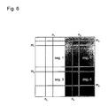
- FIG. 6 shows an example in which the amplitude / phase diagram of the transceiver module in four segments seg1 to seg4, arranged in two columns and two lines.
- a combination is created individually for each segment determined from the amplitude state and phase state m1 / n1 to m4 / n4, their individual Phase / amplitude states can be measured.
- For the reconstruction of the remaining phase / amplitude states are only those on the solid Linear phase / amplitude states are used. The one on the dashed Linear phase / amplitude states are not required for the calculation and are not measured.
- Amplitudes / phase state (x, y) State of the transceiver module with regard to amplitude and phase with a specific setting x of the amplitude adjuster and y of the phase shifter.
- Amplitude state x State of the transceiver module with a specific setting x of the amplitude adjuster with any setting of the phase shifter.
- Phase status y Status of the transceiver module for a specific setting y of the phase shifter with any setting of the amplitude adjuster.
Landscapes
- Variable-Direction Aerials And Aerial Arrays (AREA)
- Radar Systems Or Details Thereof (AREA)
- Waveguide Switches, Polarizers, And Phase Shifters (AREA)
Abstract
Description
- Fig. 1
- ein Beispiel für ein Amplituden/Phasendiagramm eines Sende-Empfangs-Moduls;
- Fig. 2
- den Verlauf der Amplitudenwerte der einzelnen Amplitudenzustände über den Phasenzuständen;
- Fig. 3
- den Verlauf der Phasenwerte der einzelnen Phasenzustände über den Amplitudenzuständen;
- Fig. 4
- ein Amplituden/Phasendiagramm zur Erläuterung des erfindungsgemäßen Synthesealgorithmus;
- Fig. 5
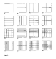
- mehrere Beispiele für die Segmentierung eines Amplituden/Phasendiagramms;
- Fig. 6
- eine weiteres Beispiel für die Segmentierung eines Amplituden/Phasendiagramms mit den tatsächlich gemessenen Zeilen und Spalten.
Fig. 5 zeigt hierzu 16 mögliche Segmentierungen für das Amplituden-Diagramm, wobei von links oben bis rechts unten fortschreitend die Segmentierung erhöht wird.
Amplitudenzustand x: Zustand des Sende-Empfangs-Moduls bei einer bestimmten Einstellung x des Amplitudenstellers bei beliebiger Einstellung des Phasenschiebers. Phasenzustand y: Zustand des Sende-Empfangs-Moduls für eine bestimmte Einstellung y des Phasenschiebers bei beliebiger Einstellung des Amplitudenstellers.
Claims (2)
- Verfahren zur Rekonstruktion des Amplituden/Phasendiagramms eines Sende-Empfangs-Moduls für eine phasengesteuerte Gruppenantenne, mit folgenden Verfahrensschritten:Messung von Amplitude und Phase der Amplituden/Phasenzustände (a,i) mit i = imin ... imax eines einzelnen Amplitudenzustands a; sowieMessung von Amplitude und Phase der Amplituden/Phasen-Zustände (j,b) mit j = jmin ... jmax eines einzelnen Phasenzustands b;Rekonstruktion der Amplituden-Werte eines Amplitudenzustands x durch Verschieben der gemessenen Amplitudenwerte des Amplitudenzustands a um die Differenz ΔA der gemessenen Amplitudenwerte der beiden Amplituden/Phasenzustände (x,b),(a,b), welche innerhalb des Phasenzustands b gleichzeitig zum Amplitudenzustand x bzw. Amplitudenzustand a gehören,Rekonstruktion der Phasen-Werte eines Phasenzustands y durch Verschieben der gemessenen Phasenwerte des Phasenzustands b um die Differenz Δ der gemessenen Phasenwerte der beiden Amplituden/Phasenzustände (a,y),(a,b), welche innerhalb des Amplitudenzustands a gleichzeitig zum Phasenzustand y bzw. zum Phasenzustand b gehören.
- Verfahren zur Rekonstruktion des Amplituden/Phasendiagramms eines Sende-Empfangs-Moduls für eine phasengesteuerte Gruppenantenne nach Anspruch 1, dadurch gekennzeichnet, dass das Amplituden/Phasendiagramm in mehrere Segmente unterteilt wird, und das Verfahren nach Anspruch 1 für jedes einzelne Segment durchgeführt wird, wobei für jedes Segment individuell ein Amplitudenzustand und ein Phasenzustand ausgewählt wird, deren Amplituden/Phasenzustände vermessen werden.
Applications Claiming Priority (2)
| Application Number | Priority Date | Filing Date | Title |
|---|---|---|---|
| DE10127080A DE10127080C1 (de) | 2001-06-02 | 2001-06-02 | Verfahren zur Rekonstruktion des Amplituden/Phasendiagramms eines Sende-Empfangs-Moduls einer phasengesteuerten Gruppenantenne |
| DE10127080 | 2001-06-02 |
Publications (2)
| Publication Number | Publication Date |
|---|---|
| EP1267442A1 true EP1267442A1 (de) | 2002-12-18 |
| EP1267442B1 EP1267442B1 (de) | 2004-11-17 |
Family
ID=7687134
Family Applications (1)
| Application Number | Title | Priority Date | Filing Date |
|---|---|---|---|
| EP02010035A Expired - Lifetime EP1267442B1 (de) | 2001-06-02 | 2002-05-06 | Verfahren zur Rekonstruktion der Amplituden/Phasendiagramme der Sende-Empfangs-Module einer phasengesteuerten Gruppenantenne |
Country Status (5)
| Country | Link |
|---|---|
| US (1) | US6744405B2 (de) |
| EP (1) | EP1267442B1 (de) |
| AT (1) | ATE282899T1 (de) |
| DE (2) | DE10127080C1 (de) |
| ES (1) | ES2232695T3 (de) |
Cited By (1)
| Publication number | Priority date | Publication date | Assignee | Title |
|---|---|---|---|---|
| EP3422476A1 (de) * | 2017-06-29 | 2019-01-02 | The Boeing Company | Elektromagnetisches feldmuster für phasengesteuerte gruppenantenne |
Families Citing this family (2)
| Publication number | Priority date | Publication date | Assignee | Title |
|---|---|---|---|---|
| US20060017058A1 (en) * | 2004-07-22 | 2006-01-26 | Taiwan Oasis Technology Co., Ltd. | Construction of LED circuit board |
| US8686896B2 (en) * | 2011-02-11 | 2014-04-01 | Src, Inc. | Bench-top measurement method, apparatus and system for phased array radar apparatus calibration |
Family Cites Families (3)
| Publication number | Priority date | Publication date | Assignee | Title |
|---|---|---|---|---|
| DE3934155C2 (de) * | 1988-10-13 | 1999-10-07 | Mitsubishi Electric Corp | Verfahren zum Messen einer Amplitude und einer Phase jedes Antennenelementes einer phasengesteuerten Antennenanordnung sowie Antennenanordnung zum Durchführen des Verfahrens |
| JP3336881B2 (ja) * | 1996-10-31 | 2002-10-21 | 三菱電機株式会社 | アンテナ測定法およびアンテナ測定装置 |
| JP2000199773A (ja) * | 1999-01-05 | 2000-07-18 | Mitsubishi Electric Corp | アンテナ開口分布測定法 |
-
2001
- 2001-06-02 DE DE10127080A patent/DE10127080C1/de not_active Expired - Fee Related
-
2002
- 2002-05-06 EP EP02010035A patent/EP1267442B1/de not_active Expired - Lifetime
- 2002-05-06 AT AT02010035T patent/ATE282899T1/de not_active IP Right Cessation
- 2002-05-06 DE DE50201547T patent/DE50201547D1/de not_active Expired - Lifetime
- 2002-05-06 ES ES02010035T patent/ES2232695T3/es not_active Expired - Lifetime
- 2002-06-03 US US10/159,291 patent/US6744405B2/en not_active Expired - Lifetime
Non-Patent Citations (1)
| Title |
|---|
| No Search * |
Cited By (3)
| Publication number | Priority date | Publication date | Assignee | Title |
|---|---|---|---|---|
| EP3422476A1 (de) * | 2017-06-29 | 2019-01-02 | The Boeing Company | Elektromagnetisches feldmuster für phasengesteuerte gruppenantenne |
| CN109212330A (zh) * | 2017-06-29 | 2019-01-15 | 波音公司 | 确定整体电磁远场方向图的方法和系统 |
| US10656234B2 (en) | 2017-06-29 | 2020-05-19 | The Boeing Company | Electromagnetic field pattern for phased array antenna |
Also Published As
| Publication number | Publication date |
|---|---|
| US6744405B2 (en) | 2004-06-01 |
| US20020190899A1 (en) | 2002-12-19 |
| DE10127080C1 (de) | 2003-01-16 |
| EP1267442B1 (de) | 2004-11-17 |
| ES2232695T3 (es) | 2005-06-01 |
| ATE282899T1 (de) | 2004-12-15 |
| DE50201547D1 (de) | 2004-12-23 |
Similar Documents
| Publication | Publication Date | Title |
|---|---|---|
| DE69701165T2 (de) | Selbst-Eichung einer Gruppenantenne mit ungleichmässiger gegenseitiger Kupplung der Antennenelemente und willkürlicher Orientierung des Antennnengitters | |
| DE102013105809B4 (de) | Multifunktionale Radaranordnung | |
| EP0452799B1 (de) | Verfahren und Vorrichtung zur automatischen Kalibrierung einer phasengesteuerten Gruppenantenne | |
| DE102010040438B4 (de) | Radarvorrichtung | |
| DE69733331T2 (de) | Verfahren zur Kalibrierung von Satellitennutzlasten mit Hybrid-Matrizen | |
| DE102018210070A1 (de) | Verfahren zur Kalibrierung eines MIMO-Radarsensors für Kraftfahrzeuge | |
| DE102021207330A1 (de) | Koordinierte miniradarzielsimulatoren für verbesserte genauigkeit und verbesserte geistersignalunterbindung | |
| DE102008023862A1 (de) | Vorrichtung und Verfahren zur Erzeugung eines Ultraschallbildes | |
| DE102021200520A1 (de) | MIMO-Radarsensor mit synchronisierten Hochfrequenzchips | |
| EP3534178B1 (de) | Radargerät mit gruppenantenne und verfahren zur quelllokalisation durch eine zweidimensionale radargruppenantenne | |
| WO2020207814A1 (de) | Verfahren zur auswertung von radarsystemen | |
| CH702504B1 (de) | Universalschnittstellenkanal-Prüfsystem. | |
| EP4214478B1 (de) | Winkelauflösendes füllstandsmessgerät | |
| WO2013135469A1 (de) | Verfahren, system und kalibrierobjekt zur automatischen kalibrierung einer bildgebenden antennenanordnung | |
| DE102021118076A1 (de) | Radar-System sowie entsprechendes Verfahren | |
| EP1267442B1 (de) | Verfahren zur Rekonstruktion der Amplituden/Phasendiagramme der Sende-Empfangs-Module einer phasengesteuerten Gruppenantenne | |
| DE3787832T2 (de) | Echtzeitanzeige der Strahlrichtung bei einer Anordnung zur Antennenstrahlsteuerung. | |
| DE19627218A1 (de) | Radarvorrichtung | |
| DE102023130868A1 (de) | Hochfrequenzprüfgerät mit einstellung des spannungsstehwellenverhältnisses und entsprechendes verfahren | |
| EP4204845B1 (de) | Mehrkanalempfangssysteme, verfahren zum kalibrieren eines mehrkanalempfangssystems und verfahren zum simulieren eines empfangs einer vorbestimmten welle an einem mehrkanalempfangssystem | |
| DE10357242A1 (de) | System und Verfahren zum Erzeugen von symetrischen modulierten Signalen mit willkürlicher Amplituden- und Phasensteuerung unter Verwendung einer Modulation | |
| WO2022129005A1 (de) | Programmierbare faseroptische verzögerungsstrecke | |
| DE19882434B4 (de) | Verfahren und Meßsystem zum Messen von Charakteristiken eines Antennensystems | |
| EP1913408A1 (de) | Messvorrichtung, insbesondere vektorieller netzwerkanalysator, mit phasenregelung | |
| DE102015210700A1 (de) | Verfahren zur Detektion von Fehlern oder Defekten an Bauteilen unter Einsatz von Ultraschallwandlern |
Legal Events
| Date | Code | Title | Description |
|---|---|---|---|
| PUAI | Public reference made under article 153(3) epc to a published international application that has entered the european phase |
Free format text: ORIGINAL CODE: 0009012 |
|
| AK | Designated contracting states |
Kind code of ref document: A1 Designated state(s): AT BE CH CY DE DK ES FI FR GB GR IE IT LI LU MC NL PT SE TR |
|
| AX | Request for extension of the european patent |
Free format text: AL;LT;LV;MK;RO;SI |
|
| 17P | Request for examination filed |
Effective date: 20030612 |
|
| AKX | Designation fees paid |
Designated state(s): AT BE CH CY DE DK ES FI FR GB GR IE IT LI LU MC NL PT SE TR |
|
| 17Q | First examination report despatched |
Effective date: 20030808 |
|
| GRAP | Despatch of communication of intention to grant a patent |
Free format text: ORIGINAL CODE: EPIDOSNIGR1 |
|
| RIC1 | Information provided on ipc code assigned before grant |
Ipc: 7H 01Q 3/26 A Ipc: 7G 01R 29/10 B |
|
| RTI1 | Title (correction) |
Free format text: METHOD FOR RECONSTRUCTION OF GAIN/PHASE-MAPS OF PHASED ARRAY ANTENNA TRANSMIT/RECEIVE-MODULES |
|
| GRAS | Grant fee paid |
Free format text: ORIGINAL CODE: EPIDOSNIGR3 |
|
| GRAA | (expected) grant |
Free format text: ORIGINAL CODE: 0009210 |
|
| AK | Designated contracting states |
Kind code of ref document: B1 Designated state(s): AT BE CH CY DE DK ES FI FR GB GR IE IT LI LU MC NL PT SE TR |
|
| PG25 | Lapsed in a contracting state [announced via postgrant information from national office to epo] |
Ref country code: FI Free format text: LAPSE BECAUSE OF FAILURE TO SUBMIT A TRANSLATION OF THE DESCRIPTION OR TO PAY THE FEE WITHIN THE PRESCRIBED TIME-LIMIT Effective date: 20041117 Ref country code: TR Free format text: LAPSE BECAUSE OF FAILURE TO SUBMIT A TRANSLATION OF THE DESCRIPTION OR TO PAY THE FEE WITHIN THE PRESCRIBED TIME-LIMIT Effective date: 20041117 Ref country code: IE Free format text: LAPSE BECAUSE OF FAILURE TO SUBMIT A TRANSLATION OF THE DESCRIPTION OR TO PAY THE FEE WITHIN THE PRESCRIBED TIME-LIMIT Effective date: 20041117 |
|
| REG | Reference to a national code |
Ref country code: GB Ref legal event code: FG4D Free format text: NOT ENGLISH |
|
| REG | Reference to a national code |
Ref country code: CH Ref legal event code: EP |
|
| REG | Reference to a national code |
Ref country code: IE Ref legal event code: FG4D Free format text: GERMAN |
|
| REF | Corresponds to: |
Ref document number: 50201547 Country of ref document: DE Date of ref document: 20041223 Kind code of ref document: P |
|
| PG25 | Lapsed in a contracting state [announced via postgrant information from national office to epo] |
Ref country code: DK Free format text: LAPSE BECAUSE OF FAILURE TO SUBMIT A TRANSLATION OF THE DESCRIPTION OR TO PAY THE FEE WITHIN THE PRESCRIBED TIME-LIMIT Effective date: 20050217 Ref country code: GR Free format text: LAPSE BECAUSE OF FAILURE TO SUBMIT A TRANSLATION OF THE DESCRIPTION OR TO PAY THE FEE WITHIN THE PRESCRIBED TIME-LIMIT Effective date: 20050217 |
|
| REG | Reference to a national code |
Ref country code: SE Ref legal event code: TRGR |
|
| GBT | Gb: translation of ep patent filed (gb section 77(6)(a)/1977) |
Effective date: 20050316 |
|
| PG25 | Lapsed in a contracting state [announced via postgrant information from national office to epo] |
Ref country code: CY Free format text: LAPSE BECAUSE OF FAILURE TO SUBMIT A TRANSLATION OF THE DESCRIPTION OR TO PAY THE FEE WITHIN THE PRESCRIBED TIME-LIMIT Effective date: 20050506 Ref country code: AT Free format text: LAPSE BECAUSE OF NON-PAYMENT OF DUE FEES Effective date: 20050506 Ref country code: LU Free format text: LAPSE BECAUSE OF NON-PAYMENT OF DUE FEES Effective date: 20050506 |
|
| PG25 | Lapsed in a contracting state [announced via postgrant information from national office to epo] |
Ref country code: MC Free format text: LAPSE BECAUSE OF NON-PAYMENT OF DUE FEES Effective date: 20050531 Ref country code: BE Free format text: LAPSE BECAUSE OF NON-PAYMENT OF DUE FEES Effective date: 20050531 |
|
| REG | Reference to a national code |
Ref country code: ES Ref legal event code: FG2A Ref document number: 2232695 Country of ref document: ES Kind code of ref document: T3 |
|
| REG | Reference to a national code |
Ref country code: IE Ref legal event code: FD4D |
|
| PLBE | No opposition filed within time limit |
Free format text: ORIGINAL CODE: 0009261 |
|
| STAA | Information on the status of an ep patent application or granted ep patent |
Free format text: STATUS: NO OPPOSITION FILED WITHIN TIME LIMIT |
|
| 26N | No opposition filed |
Effective date: 20050818 |
|
| ET | Fr: translation filed | ||
| BERE | Be: lapsed |
Owner name: EADS DEUTSCHLAND G.M.B.H. Effective date: 20050531 |
|
| PG25 | Lapsed in a contracting state [announced via postgrant information from national office to epo] |
Ref country code: CH Free format text: LAPSE BECAUSE OF NON-PAYMENT OF DUE FEES Effective date: 20060531 Ref country code: LI Free format text: LAPSE BECAUSE OF NON-PAYMENT OF DUE FEES Effective date: 20060531 |
|
| REG | Reference to a national code |
Ref country code: CH Ref legal event code: PL |
|
| BERE | Be: lapsed |
Owner name: *EADS DEUTSCHLAND G.M.B.H. Effective date: 20050531 |
|
| PG25 | Lapsed in a contracting state [announced via postgrant information from national office to epo] |
Ref country code: PT Free format text: LAPSE BECAUSE OF NON-PAYMENT OF DUE FEES Effective date: 20050417 |
|
| REG | Reference to a national code |
Ref country code: DE Ref legal event code: R081 Ref document number: 50201547 Country of ref document: DE Owner name: AIRBUS DEFENCE AND SPACE GMBH, DE Free format text: FORMER OWNER: EADS DEUTSCHLAND GMBH, 85521 OTTOBRUNN, DE Effective date: 20140916 Ref country code: DE Ref legal event code: R081 Ref document number: 50201547 Country of ref document: DE Owner name: AIRBUS DS ELECTRONICS AND BORDER SECURITY GMBH, DE Free format text: FORMER OWNER: EADS DEUTSCHLAND GMBH, 85521 OTTOBRUNN, DE Effective date: 20140916 Ref country code: DE Ref legal event code: R081 Ref document number: 50201547 Country of ref document: DE Owner name: HENSOLDT SENSORS GMBH, DE Free format text: FORMER OWNER: EADS DEUTSCHLAND GMBH, 85521 OTTOBRUNN, DE Effective date: 20140916 |
|
| REG | Reference to a national code |
Ref country code: FR Ref legal event code: PLFP Year of fee payment: 14 |
|
| REG | Reference to a national code |
Ref country code: DE Ref legal event code: R081 Ref document number: 50201547 Country of ref document: DE Owner name: AIRBUS DS ELECTRONICS AND BORDER SECURITY GMBH, DE Free format text: FORMER OWNER: AIRBUS DEFENCE AND SPACE GMBH, 85521 OTTOBRUNN, DE Ref country code: FR Ref legal event code: PLFP Year of fee payment: 15 Ref country code: DE Ref legal event code: R081 Ref document number: 50201547 Country of ref document: DE Owner name: HENSOLDT SENSORS GMBH, DE Free format text: FORMER OWNER: AIRBUS DEFENCE AND SPACE GMBH, 85521 OTTOBRUNN, DE |
|
| PGFP | Annual fee paid to national office [announced via postgrant information from national office to epo] |
Ref country code: NL Payment date: 20160519 Year of fee payment: 15 |
|
| PGFP | Annual fee paid to national office [announced via postgrant information from national office to epo] |
Ref country code: GB Payment date: 20160520 Year of fee payment: 15 Ref country code: ES Payment date: 20160512 Year of fee payment: 15 Ref country code: DE Payment date: 20160520 Year of fee payment: 15 |
|
| PGFP | Annual fee paid to national office [announced via postgrant information from national office to epo] |
Ref country code: SE Payment date: 20160519 Year of fee payment: 15 Ref country code: FR Payment date: 20160520 Year of fee payment: 15 Ref country code: IT Payment date: 20160524 Year of fee payment: 15 |
|
| REG | Reference to a national code |
Ref country code: DE Ref legal event code: R082 Ref document number: 50201547 Country of ref document: DE Representative=s name: LIFETECH IP SPIES & BEHRNDT PATENTANWAELTE PAR, DE Ref country code: DE Ref legal event code: R081 Ref document number: 50201547 Country of ref document: DE Owner name: HENSOLDT SENSORS GMBH, DE Free format text: FORMER OWNER: AIRBUS DS ELECTRONICS AND BORDER SECURITY GMBH, 82024 TAUFKIRCHEN, DE |
|
| REG | Reference to a national code |
Ref country code: DE Ref legal event code: R119 Ref document number: 50201547 Country of ref document: DE |
|
| REG | Reference to a national code |
Ref country code: SE Ref legal event code: EUG |
|
| REG | Reference to a national code |
Ref country code: NL Ref legal event code: MM Effective date: 20170601 |
|
| GBPC | Gb: european patent ceased through non-payment of renewal fee |
Effective date: 20170506 |
|
| PG25 | Lapsed in a contracting state [announced via postgrant information from national office to epo] |
Ref country code: SE Free format text: LAPSE BECAUSE OF NON-PAYMENT OF DUE FEES Effective date: 20170507 |
|
| REG | Reference to a national code |
Ref country code: FR Ref legal event code: ST Effective date: 20180131 |
|
| PG25 | Lapsed in a contracting state [announced via postgrant information from national office to epo] |
Ref country code: NL Free format text: LAPSE BECAUSE OF NON-PAYMENT OF DUE FEES Effective date: 20170601 |
|
| PG25 | Lapsed in a contracting state [announced via postgrant information from national office to epo] |
Ref country code: DE Free format text: LAPSE BECAUSE OF NON-PAYMENT OF DUE FEES Effective date: 20171201 Ref country code: GB Free format text: LAPSE BECAUSE OF NON-PAYMENT OF DUE FEES Effective date: 20170506 |
|
| PG25 | Lapsed in a contracting state [announced via postgrant information from national office to epo] |
Ref country code: FR Free format text: LAPSE BECAUSE OF NON-PAYMENT OF DUE FEES Effective date: 20170531 Ref country code: IT Free format text: LAPSE BECAUSE OF NON-PAYMENT OF DUE FEES Effective date: 20170506 |
|
| REG | Reference to a national code |
Ref country code: ES Ref legal event code: FD2A Effective date: 20180629 |
|
| PG25 | Lapsed in a contracting state [announced via postgrant information from national office to epo] |
Ref country code: ES Free format text: LAPSE BECAUSE OF NON-PAYMENT OF DUE FEES Effective date: 20170507 |