EP1267078A2 - Fluid transfer machine with drive shaft lubrication and cooling - Google Patents
Fluid transfer machine with drive shaft lubrication and cooling Download PDFInfo
- Publication number
- EP1267078A2 EP1267078A2 EP02254183A EP02254183A EP1267078A2 EP 1267078 A2 EP1267078 A2 EP 1267078A2 EP 02254183 A EP02254183 A EP 02254183A EP 02254183 A EP02254183 A EP 02254183A EP 1267078 A2 EP1267078 A2 EP 1267078A2
- Authority
- EP
- European Patent Office
- Prior art keywords
- drive shaft
- fluid
- pumping mechanism
- port
- housing
- Prior art date
- Legal status (The legal status is an assumption and is not a legal conclusion. Google has not performed a legal analysis and makes no representation as to the accuracy of the status listed.)
- Granted
Links
Images



Classifications
-
- F—MECHANICAL ENGINEERING; LIGHTING; HEATING; WEAPONS; BLASTING
- F04—POSITIVE - DISPLACEMENT MACHINES FOR LIQUIDS; PUMPS FOR LIQUIDS OR ELASTIC FLUIDS
- F04C—ROTARY-PISTON, OR OSCILLATING-PISTON, POSITIVE-DISPLACEMENT MACHINES FOR LIQUIDS; ROTARY-PISTON, OR OSCILLATING-PISTON, POSITIVE-DISPLACEMENT PUMPS
- F04C15/00—Component parts, details or accessories of machines, pumps or pumping installations, not provided for in groups F04C2/00 - F04C14/00
- F04C15/06—Arrangements for admission or discharge of the working fluid, e.g. constructional features of the inlet or outlet
-
- F—MECHANICAL ENGINEERING; LIGHTING; HEATING; WEAPONS; BLASTING
- F04—POSITIVE - DISPLACEMENT MACHINES FOR LIQUIDS; PUMPS FOR LIQUIDS OR ELASTIC FLUIDS
- F04C—ROTARY-PISTON, OR OSCILLATING-PISTON, POSITIVE-DISPLACEMENT MACHINES FOR LIQUIDS; ROTARY-PISTON, OR OSCILLATING-PISTON, POSITIVE-DISPLACEMENT PUMPS
- F04C15/00—Component parts, details or accessories of machines, pumps or pumping installations, not provided for in groups F04C2/00 - F04C14/00
- F04C15/0057—Driving elements, brakes, couplings, transmission specially adapted for machines or pumps
- F04C15/0061—Means for transmitting movement from the prime mover to driven parts of the pump, e.g. clutches, couplings, transmissions
- F04C15/0073—Couplings between rotors and input or output shafts acting by interengaging or mating parts, i.e. positive coupling of rotor and shaft
-
- F—MECHANICAL ENGINEERING; LIGHTING; HEATING; WEAPONS; BLASTING
- F04—POSITIVE - DISPLACEMENT MACHINES FOR LIQUIDS; PUMPS FOR LIQUIDS OR ELASTIC FLUIDS
- F04C—ROTARY-PISTON, OR OSCILLATING-PISTON, POSITIVE-DISPLACEMENT MACHINES FOR LIQUIDS; ROTARY-PISTON, OR OSCILLATING-PISTON, POSITIVE-DISPLACEMENT PUMPS
- F04C15/00—Component parts, details or accessories of machines, pumps or pumping installations, not provided for in groups F04C2/00 - F04C14/00
- F04C15/0088—Lubrication
-
- F—MECHANICAL ENGINEERING; LIGHTING; HEATING; WEAPONS; BLASTING
- F04—POSITIVE - DISPLACEMENT MACHINES FOR LIQUIDS; PUMPS FOR LIQUIDS OR ELASTIC FLUIDS
- F04C—ROTARY-PISTON, OR OSCILLATING-PISTON, POSITIVE-DISPLACEMENT MACHINES FOR LIQUIDS; ROTARY-PISTON, OR OSCILLATING-PISTON, POSITIVE-DISPLACEMENT PUMPS
- F04C15/00—Component parts, details or accessories of machines, pumps or pumping installations, not provided for in groups F04C2/00 - F04C14/00
- F04C15/0096—Heating; Cooling
-
- F—MECHANICAL ENGINEERING; LIGHTING; HEATING; WEAPONS; BLASTING
- F04—POSITIVE - DISPLACEMENT MACHINES FOR LIQUIDS; PUMPS FOR LIQUIDS OR ELASTIC FLUIDS
- F04C—ROTARY-PISTON, OR OSCILLATING-PISTON, POSITIVE-DISPLACEMENT MACHINES FOR LIQUIDS; ROTARY-PISTON, OR OSCILLATING-PISTON, POSITIVE-DISPLACEMENT PUMPS
- F04C2/00—Rotary-piston machines or pumps
- F04C2/08—Rotary-piston machines or pumps of intermeshing-engagement type, i.e. with engagement of co-operating members similar to that of toothed gearing
- F04C2/12—Rotary-piston machines or pumps of intermeshing-engagement type, i.e. with engagement of co-operating members similar to that of toothed gearing of other than internal-axis type
- F04C2/14—Rotary-piston machines or pumps of intermeshing-engagement type, i.e. with engagement of co-operating members similar to that of toothed gearing of other than internal-axis type with toothed rotary pistons
- F04C2/18—Rotary-piston machines or pumps of intermeshing-engagement type, i.e. with engagement of co-operating members similar to that of toothed gearing of other than internal-axis type with toothed rotary pistons with similar tooth forms
Definitions
- the present invention relates generally to a fluid transfer machine, and more particularly to a fluid transfer machine that can be used as a pump or motor.
- Fluid transfer machines can have different types of pumping mechanisms to move fluid through the machine.
- One type of pumping mechanism useful for a variety of fluid transfer machines is a positive displacement rotary pump.
- Conventional positive displacement rotary pumps include single rotors (vane, piston, progressing cavity, screw or peristaltic), or multiple rotors (internal/external gear, lobe, circumferential piston or screw). The mechanisms all have advantages and drawbacks, depending on the fluid to be pumped, and the particular application.
- Fluid is typically used for lubricating the moving parts of the pumping mechanism. It is particularly advantageous to use a portion of the fluid being transferred through the machine as the cooling and lubricating fluid. It is well-known to provide additional flow passages through the housing of the machine and to tap or bleed off a portion of the fluid from the primary flow for use in lubrication and cooling. It is also known to intentionally provide leak paths between the moving components and then collect the fluid for return to the primary flow path. Examples of such machines are shown in Patent Specification US-A-6,048,185 to Ishizuka; Patent Specification US-A-3,994,634 to Riddle; and Patent Specification US-A-2,940,399 to Zieg.
- a fluid transfer machine comprising a housing including a first fluid port and a second fluid port, and enclosing a pumping mechanism, a primary flow path defined from the first port through the pumping mechanism to the second port, a drive shaft engaging the pumping mechanism and extending outwardly from the housing, the drive shaft rotatable to operate the pumping mechanism and transfer fluid from the first port to the second port through the primary flow path, wherein the drive shaft is located in the primary flow path through the housing.
- a novel and unique fluid transfer machine particularly useful as a pump or motor is provided where the drive shaft (as well as the pump mechanism) is properly lubricated and cooled, and which has a compact design that is easily-manufactured.
- the fluid transfer machine has a pumping mechanism that is a positive displacement, rotary (single or multiple rotor) type pump appropriate for the particular application.
- An external gear-type pump is used in a preferred form of the invention.
- the machine can be run as a motor or as a pump, as should be well know, typically by reversing the rotation of the pumping mechanism.
- the pumping mechanism includes a typical arrangement of components such as bearings and stub shafts, which are preferably lubricated in a conventional manner, such as by allowing a slight leak path between the moving components.
- the pumping mechanism is driven by a drive shaft, which extends out of the housing and is acted upon by (or acts upon) an external device.
- the drive shaft is located in the primary flow path through the fluid transfer machine.
- the drive shaft is located in the inlet flow path of the primary flow.
- the primary flow is directed from the inlet port to a cavity that surrounds the drive shaft, at a location between a pair of journal bearings or sleeves. The flow then continues to the suction side of the pumping mechanism.
- the drive shaft could be located in the outlet flow path of the primary flow path, between the pressure side of the pumping mechanism and the outlet port.
- the primary flow cools and lubricates the drive shaft (and drive shaft bearings), and reduces the size of the fluid transfer machine, as additional cooling and lubrication flow passage(s) are not necessary. This also reduces the complexity of manufacture of the machine.
- the present invention thereby addresses many of the issues with prior machines, and provides a fluid transfer machine, particularly useful as a pump or motor, where the drive shaft (as well as the pump mechanism) is lubricated and cooled, and which has a compact design that is easily-manufactured.
- a positive displacement, rotary-type fluid transfer machine is indicated generally at 20.
- the machine has a housing or body 21, with a first, inlet port 22, and a second, outlet port 23.
- a drive shaft 26 projects outwardly from the housing and can be rotated to operate a pumping mechanism internal to the housing.
- the machine could have any type of positive displacement rotary-type pump such as a single rotor (e.g., vane, piston, progressing cavity, screw or peristaltic); or multiple rotor (e.g., internal/external gear, lobe, circumferential piston or screw) pump. It should also be well-known that the machine could be operated as a pump or a motor, depending on the rotation of the drive shaft 26, and the connections to ports 22 and 23.
- a single rotor e.g., vane, piston, progressing cavity, screw or peristaltic
- multiple rotor e.g., internal/external gear, lobe, circumferential piston or screw
- the housing 21 consists of three cylindrical sections 30, 31 and 32, which are arranged end-to-end in a conventional manner, and screwed together such as with elongated bolts 35.
- Inlet port 22 is provided in end section 32, while outlet port 23 is provided in end section 30.
- inlet and outlet ports 22, 23 could alternatively be formed in only one of the sections and/or in middle section 31, or could be located at one or both of the axial ends of the housing.
- appropriate seals 36 are provided between the sections to prevent fluid leakage.
- Middle section 31 includes a central chamber 37, which receives a pumping mechanism, indicated generally at 40.
- Chamber 37 is closed at either end by opposing end surfaces of sections 30 and 32.
- Pumping mechanism 40 preferably comprises an external gear-type mechanism, with three gears 42, 43, 44 supported for rotation on stub shafts 46, 47, and drive shaft 26, respectively (see, e.g., Figure 7).
- Stub shafts 46, 47 are closely received, preferably with press-fit, in blind end bores 48, 49, respectively, extending inwardly from one end of the housing, such that shafts 46, 47 are prevented from rotating relative to the housing.
- Gears 42, 43 are received for rotation on stub shafts 46, 47; while drive shaft 26 is received with a key-in-groove or is fixed by other appropriate means to central gear 44.
- Gear 44 is interposed between gears 42 and 43, such that gears gear pair 42, 44 have teeth that intermesh during rotation, and gear pair 43, 44 also have teeth that intermesh during rotation.
- central gear 44 rotates both outer gears 42, 43, simultaneously which in turn, create expanding and contracting pockets for transfer of fluid.
- Inlet port 22 is fluid connected to the suction side of the pumping mechanism, that is, at a location where the pockets between the gear teeth are expanding.
- Outlet port 23 in contrast, is fluidly connected to the pressure side of the pumping mechanism, that is, at a location where the pockets in the gear teeth are contracting.
- inlet port 22 is fluidly connected to a single inlet passage portion 49, which divides into a pair of passages 50a, 50b, each of which is fluidly connected to the suction side of each gear pair 42, 44 and 43, 44, respectively.
- a pair of passages 53a, 53b are fluidly-connected to the pressure side of the pumping mechanism, and then combine and lead to a single outlet passage portion 54, which is fluidly connected to outlet port 23.
- a primary flow path is thereby established from the inlet port 22 through inlet passages 49, 50a, 50b; through the expanding and contracting pockets of the gears 42-44; and through outlet passages 53a, 53b, 54 to outlet port 23.
- the structure describe above is fairly conventional in three-gear, external gear-type pumping mechanism, as should be appreciated by those skilled in the art.
- the three- gear pumping mechanism is only exemplary in nature, and other pumping mechanisms could be used, depending upon the particular application.
- only two intermeshing gears could be provided, with only a single passage leading to the suction side, and a single passage leading from the pressure side; or an entirely different type of pumping mechanism, such as a single rotor (vane, piston, progressing cavity, screw or peristaltic), or other multiple rotor (internal/external gear, lobe, circumferential piston or screw), could be used.
- the present invention provides a means to cool and lubricate the drive shaft during rotation of the gears.
- the drive shaft is typically supported on annular bearings, such as sleeve or journal bearings 60, 61.
- Bearings 60, 61 are spaced apart axially along the drive shaft, with bearing 60 located closer to the pumping mechanism, and bearing 61 located closer to the distal end of the drive shaft.
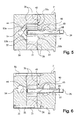
- a cavity 65 is provided in housing section 32 in surrounding relation to shaft 26, and between the bearings 60, 61. Cavity 65 can be easily formed during the manufacture of the end housing section 32. Cavity 65 is located in the primary flow path and received fluid directly from the inlet passage 49, and then delivers the fluid directly to inlet passages 50a, 50b to the pumping mechanism.
- Fluid entering the inlet port 22 thereby flows through the port and completely surrounds drive shaft 26, where the fluid provides lubrication and cooling of the drive shaft.
- the fluid seeps through bearings 60, 61, and thereby also provides cooling and lubrication of the drive shaft bearings.
- Helical or spiral grooves, such as at 68 ( Figures 5, 6, 8) assist in directing fluid along the shaft to cool and lubricate the shaft, as well as the bearings 60, 61.
- a fluid seal surrounding shaft 26 can be provided axially outward from outer bearing 61, or a seal could be provided on an external component engaging shaft 26 and sealing against housing section 32 in the area surrounding shaft 26.
- the machine could be operated in a reverse manner, such that port 22 is an outlet port, and the fluid is provided from the pressure side of the pumping mechanism 40 through passages 50a, 50b to cavity 65, and then to passage 49 and port 22.
- the direction of rotation of drive shaft 26 determines whether the machine operates as a pump or motor, as should be well-known to those skilled in the art.
- the present invention addresses many of the issues with prior machines, and provides a fluid transfer machine, particularly useful as a pump or motor, where the drive shaft (as well as the pump mechanism) is lubricated and cooled, and which has a compact design that is easily-manufactured.
- the primary flow path is used to cool and lubricate the drive shaft (and drive shaft bearings) without the need for additional passages through the housing.
Landscapes
- Engineering & Computer Science (AREA)
- Mechanical Engineering (AREA)
- General Engineering & Computer Science (AREA)
- Rotary Pumps (AREA)
- Applications Or Details Of Rotary Compressors (AREA)
- Compressor (AREA)
- Heat Treatment Of Articles (AREA)
- Details Of Reciprocating Pumps (AREA)
Abstract
Description
Claims (9)
- A fluid transfer machine (20), comprising:a housing (21) including a first fluid port (22) and a second fluid port (23), and enclosing a pumping mechanism (40), a primary flow path (22, 49, 50a, 50b, 42-44, 53a, 53b, 54, 23) defined from the first port (22) through the pumping mechanism (40) to the second port (23), a drive shaft (26) engaging the pumping mechanism (40) and extending outwardly from the housing (21), the drive shaft (26) rotatable to operate the pumping mechanism (40) and transfer fluid from the first port (22) to the second port (23) through the primary flow path , characterized in that the drive shaft (26) is located in the primary flow path (22, 49, 50a, 50b, 42-44, 53a, 53b, 54, 23) through the housing (21).
- A fluid transfer machine (20) as claimed in claim 1, wherein a cavity (65) surrounds a portion of the drive shaft (26), and the primary flow path (22, 49, 50a, 50b, 42-44, 53a, 53b, 54, 23) is defined through the cavity (65).
- A fluid transfer machine (20) as claimed in claim 2, wherein a pair of bearings (60, 61) support the drive shaft (26) and are spaced apart along the drive shaft (26), the cavity (65) being located between the bearings (60, 61).
- A fluid transfer machine (20) as claimed in claim 3, wherein the housing (21) includes housing sections (30, 31, 32) disposed in end-to-end relation to one another, the housing sections (30, 31, 32) including a middle housing section (31) and a pair of end sections (30, 32) on opposite sides of the middle section (31), the pumping mechanism (40) being located in a chamber (37) in the middle housing section (31), and the cavity (65) and bearings (60, 61) being located in one of the end sections (32).
- A fluid transfer machine (20) as claimed in claim 4, wherein a first passage portion (49) fluidly interconnects the first port (22) directly with the cavity (65), and a pair of passage portions (50a, 50b) fluidly interconnect the cavity (65) directly with the pumping mechanism (40).
- A fluid transfer machine (20) as claimed in any one of the previous claims, wherein the fluid transfer machine comprises a pump.
- A fluid transfer machine (20) as claimed in any one of the previous claims, wherein the fluid transfer machine comprises a motor.
- A fluid transfer machine (20) as claimed in any one of the previous claims, wherein the pumping mechanism (40) comprises a set of rotatably supported gears (42, 43, 44) with intermeshing teeth, one of said gears (44) supported for rotation on drive shaft (26).
- A method for transferring fluid through a machine (20), where the machine (20) includes a housing (21) having an inlet port (22) and an outlet port (28), and encloses a pumping mechanism (40), a primary flow path (22, 49, 50a, 50b, 42-44, 53a, 53b, 54, 23) defined from the inlet port (22) through the pumping mechanism (14) to the outlet port (23), a drive shaft (26) engaging the pumping mechanism (48) and extending outwardly from the housing (21), the drive shaft (26) rotatable to operate the pumping mechanism (44) and transfer fluid from the inlet port (22) to the outlet port (23) through the primary flow path, characterized in that the housing includes cavity (65) in the primary flow path (22, 49, 50a, 50b, 42-44, 53a, 53b, 54, 23) surrounding the drive shaft (26), fluidly connected to the inlet port (22) and to the pumping mechanism (44) and wherein the method comprises the steps of: directing fluid from the inlet port (22) into the cavity (65) around the drive shaft (26) to cool and lubricate the drive shaft, directing the fluid from the drive shaft (26) to the pumping mechanism (44), and then directing the fluid from the pumping mechanism (44) to the outlet port (23).
Applications Claiming Priority (2)
| Application Number | Priority Date | Filing Date | Title |
|---|---|---|---|
| US29830101P | 2001-06-14 | 2001-06-14 | |
| US298301P | 2001-06-14 |
Publications (3)
| Publication Number | Publication Date |
|---|---|
| EP1267078A2 true EP1267078A2 (en) | 2002-12-18 |
| EP1267078A3 EP1267078A3 (en) | 2003-05-14 |
| EP1267078B1 EP1267078B1 (en) | 2006-02-01 |
Family
ID=23149913
Family Applications (1)
| Application Number | Title | Priority Date | Filing Date |
|---|---|---|---|
| EP02254183A Expired - Lifetime EP1267078B1 (en) | 2001-06-14 | 2002-06-14 | Fluid transfer machine with drive shaft lubrication and cooling |
Country Status (4)
| Country | Link |
|---|---|
| US (1) | US6685453B2 (en) |
| EP (1) | EP1267078B1 (en) |
| AT (1) | ATE317065T1 (en) |
| DE (1) | DE60208979T2 (en) |
Cited By (2)
| Publication number | Priority date | Publication date | Assignee | Title |
|---|---|---|---|---|
| EP1491800A1 (en) * | 2003-06-27 | 2004-12-29 | Parker-Hannifin Corporation | Compliant viscous seal for fluid transfer device |
| CN102529389A (en) * | 2010-09-27 | 2012-07-04 | 施乐公司 | Ink pump with fluid and particulate return flow path |
Families Citing this family (6)
| Publication number | Priority date | Publication date | Assignee | Title |
|---|---|---|---|---|
| JP2006152914A (en) * | 2004-11-29 | 2006-06-15 | Hitachi Ltd | Oil pump |
| DK177834B1 (en) * | 2013-02-27 | 2014-09-08 | C C Jensen As | Device for processing a liquid under vacuum pressure |
| CZ201597A3 (en) * | 2015-02-13 | 2016-02-24 | Jihostroj A.S. | Gear-type pump with a drive |
| DE102023111408A1 (en) * | 2023-05-03 | 2024-11-07 | Itt Bornemann Gmbh | Single-flow screw pump |
| DE102023129457A1 (en) | 2023-10-25 | 2025-04-30 | Itt Bornemann Gmbh | Pump and method for adjusting the flow rate of a pump |
| DE102023133839A1 (en) | 2023-12-04 | 2025-06-05 | Itt Bornemann Gmbh | pump |
Family Cites Families (18)
| Publication number | Priority date | Publication date | Assignee | Title |
|---|---|---|---|---|
| US1460875A (en) | 1921-09-27 | 1923-07-03 | Baxter D Whitney & Son Inc | Rotary gear pump |
| CH133559A (en) * | 1927-08-25 | 1929-06-15 | Rozier Gabriel | Two-axis rotary pump. |
| US1927749A (en) * | 1928-07-03 | 1933-09-19 | Firm Martin Holken G M B H | Artificial silk spinning pump |
| DE563101C (en) | 1931-08-01 | 1932-11-02 | Carl Hamel Akt Ges | Gear spinning pump for rayon spinning machines |
| US2526964A (en) | 1946-11-12 | 1950-10-24 | Gen Mecanique Appliquee Soc In | Adjustable gearing |
| US2940399A (en) | 1958-04-25 | 1960-06-14 | Symington Wayne Corp | Hydro-balanced pump |
| US2998783A (en) * | 1958-04-25 | 1961-09-05 | John C Lee | Pressure-balanced gear pump |
| NL6410753A (en) * | 1964-09-16 | 1966-03-17 | ||
| NL6504738A (en) | 1965-04-14 | 1966-10-17 | ||
| GB1182608A (en) * | 1966-06-07 | 1970-02-25 | Plessey Co Ltd | Improvements in or relating to Rotary Pumps for Liquids Containing Solid Contaminants |
| DE2421599A1 (en) | 1974-05-04 | 1975-11-13 | Bosch Gmbh Robert | GEAR PUMP |
| US3994634A (en) | 1975-10-28 | 1976-11-30 | Rockwell International Corporation | Reversible lubricant pump |
| SE445245B (en) | 1982-06-23 | 1986-06-09 | Jerzy Janczak | HYDRAULIC PUMP OR HYDRAULIC ENGINE |
| US5083909A (en) | 1990-11-29 | 1992-01-28 | The United States Of America As Represented By The Secretary Of The Navy | Seawater hydraulic vane type pump |
| ES2110799T3 (en) | 1995-05-24 | 1998-02-16 | Maag Pump Systems Ag | BEARING ARRANGEMENT FOR A SHAFT OF A PUMP TO IMPELLER MEDIA WITH DIFFERENT VISCOSITY. |
| JPH10131889A (en) | 1996-10-25 | 1998-05-19 | Mitsubishi Heavy Ind Ltd | Compressor for refrigerator |
| JP3387780B2 (en) | 1997-06-24 | 2003-03-17 | 株式会社日立ユニシアオートモティブ | Hydraulic pump |
| JP3387781B2 (en) | 1997-06-24 | 2003-03-17 | 株式会社日立ユニシアオートモティブ | Hydraulic pump |
-
2002
- 2002-05-31 US US10/160,835 patent/US6685453B2/en not_active Expired - Fee Related
- 2002-06-14 EP EP02254183A patent/EP1267078B1/en not_active Expired - Lifetime
- 2002-06-14 AT AT02254183T patent/ATE317065T1/en not_active IP Right Cessation
- 2002-06-14 DE DE60208979T patent/DE60208979T2/en not_active Expired - Lifetime
Cited By (4)
| Publication number | Priority date | Publication date | Assignee | Title |
|---|---|---|---|---|
| EP1491800A1 (en) * | 2003-06-27 | 2004-12-29 | Parker-Hannifin Corporation | Compliant viscous seal for fluid transfer device |
| US7278840B2 (en) | 2003-06-27 | 2007-10-09 | Parker-Hannifin Corporation | Compliant viscous seal for fluid transfer device |
| CN102529389A (en) * | 2010-09-27 | 2012-07-04 | 施乐公司 | Ink pump with fluid and particulate return flow path |
| CN102529389B (en) * | 2010-09-27 | 2014-11-26 | 施乐公司 | Ink pump with fluid and particulate return flow path |
Also Published As
| Publication number | Publication date |
|---|---|
| US6685453B2 (en) | 2004-02-03 |
| EP1267078A3 (en) | 2003-05-14 |
| DE60208979T2 (en) | 2006-08-17 |
| US20030059329A1 (en) | 2003-03-27 |
| DE60208979D1 (en) | 2006-04-13 |
| ATE317065T1 (en) | 2006-02-15 |
| EP1267078B1 (en) | 2006-02-01 |
Similar Documents
| Publication | Publication Date | Title |
|---|---|---|
| US8535030B2 (en) | Gerotor hydraulic pump with fluid actuated vanes | |
| EP3701151B1 (en) | Lubricant supply passage for compressor background | |
| EP1927758A1 (en) | Oil-free fluid machine having two or more rotors | |
| EP1267078B1 (en) | Fluid transfer machine with drive shaft lubrication and cooling | |
| GB2278402A (en) | Helical gear fluid machine. | |
| CN105121783A (en) | Screw pump | |
| CN108930649B9 (en) | Compressor with oil management system | |
| US4035113A (en) | Gerotor device with lubricant system | |
| JP6427430B2 (en) | Screw compressor | |
| US6663367B2 (en) | Shaft seal structure of vacuum pumps | |
| US6692244B2 (en) | Hydraulic pump utilizing floating shafts | |
| WO2007074807A1 (en) | Screw-type fluid machine | |
| JPH0275783A (en) | Trochoid pump | |
| JPH094570A (en) | Pump device | |
| CN111247342B (en) | Internal exhaust passage for compressor | |
| JP4248055B2 (en) | Oil-cooled screw compressor | |
| US5217361A (en) | Fluid compressor having lubrication for two spiral blade compression sections | |
| US20050084397A1 (en) | Gas compressor | |
| JP6767948B2 (en) | Oil-cooled two-stage screw compressor | |
| JP3664498B2 (en) | Vacuum pump | |
| US20230392683A1 (en) | Gerotor Pump as for a Transmission | |
| CN110318997A (en) | Rotary pump | |
| JP7811460B2 (en) | Screw Compressor | |
| JP2002106476A (en) | Gear pump | |
| WO2025052980A1 (en) | Screw compressor and gas compression facility |
Legal Events
| Date | Code | Title | Description |
|---|---|---|---|
| PUAI | Public reference made under article 153(3) epc to a published international application that has entered the european phase |
Free format text: ORIGINAL CODE: 0009012 |
|
| AK | Designated contracting states |
Kind code of ref document: A2 Designated state(s): AT BE CH CY DE DK ES FI FR GB GR IE IT LI LU MC NL PT SE TR |
|
| AX | Request for extension of the european patent |
Free format text: AL;LT;LV;MK;RO;SI |
|
| PUAL | Search report despatched |
Free format text: ORIGINAL CODE: 0009013 |
|
| AK | Designated contracting states |
Designated state(s): AT BE CH CY DE DK ES FI FR GB GR IE IT LI LU MC NL PT SE TR |
|
| AX | Request for extension of the european patent |
Extension state: AL LT LV MK RO SI |
|
| 17P | Request for examination filed |
Effective date: 20031008 |
|
| AKX | Designation fees paid |
Designated state(s): AT BE CH CY DE DK ES FI FR GB GR IE IT LI LU MC NL PT SE TR |
|
| 17Q | First examination report despatched |
Effective date: 20040309 |
|
| RAP1 | Party data changed (applicant data changed or rights of an application transferred) |
Owner name: CONSTELLATION PUMPS CORPORATION |
|
| GRAP | Despatch of communication of intention to grant a patent |
Free format text: ORIGINAL CODE: EPIDOSNIGR1 |
|
| GRAS | Grant fee paid |
Free format text: ORIGINAL CODE: EPIDOSNIGR3 |
|
| GRAA | (expected) grant |
Free format text: ORIGINAL CODE: 0009210 |
|
| AK | Designated contracting states |
Kind code of ref document: B1 Designated state(s): AT BE CH CY DE DK ES FI FR GB GR IE IT LI LU MC NL PT SE TR |
|
| PG25 | Lapsed in a contracting state [announced via postgrant information from national office to epo] |
Ref country code: IT Free format text: LAPSE BECAUSE OF FAILURE TO SUBMIT A TRANSLATION OF THE DESCRIPTION OR TO PAY THE FEE WITHIN THE PRESCRIBED TIME-LIMIT;WARNING: LAPSES OF ITALIAN PATENTS WITH EFFECTIVE DATE BEFORE 2007 MAY HAVE OCCURRED AT ANY TIME BEFORE 2007. THE CORRECT EFFECTIVE DATE MAY BE DIFFERENT FROM THE ONE RECORDED. Effective date: 20060201 Ref country code: BE Free format text: LAPSE BECAUSE OF FAILURE TO SUBMIT A TRANSLATION OF THE DESCRIPTION OR TO PAY THE FEE WITHIN THE PRESCRIBED TIME-LIMIT Effective date: 20060201 Ref country code: CH Free format text: LAPSE BECAUSE OF FAILURE TO SUBMIT A TRANSLATION OF THE DESCRIPTION OR TO PAY THE FEE WITHIN THE PRESCRIBED TIME-LIMIT Effective date: 20060201 Ref country code: FI Free format text: LAPSE BECAUSE OF FAILURE TO SUBMIT A TRANSLATION OF THE DESCRIPTION OR TO PAY THE FEE WITHIN THE PRESCRIBED TIME-LIMIT Effective date: 20060201 Ref country code: AT Free format text: LAPSE BECAUSE OF FAILURE TO SUBMIT A TRANSLATION OF THE DESCRIPTION OR TO PAY THE FEE WITHIN THE PRESCRIBED TIME-LIMIT Effective date: 20060201 Ref country code: LI Free format text: LAPSE BECAUSE OF FAILURE TO SUBMIT A TRANSLATION OF THE DESCRIPTION OR TO PAY THE FEE WITHIN THE PRESCRIBED TIME-LIMIT Effective date: 20060201 Ref country code: NL Free format text: LAPSE BECAUSE OF FAILURE TO SUBMIT A TRANSLATION OF THE DESCRIPTION OR TO PAY THE FEE WITHIN THE PRESCRIBED TIME-LIMIT Effective date: 20060201 |
|
| REG | Reference to a national code |
Ref country code: GB Ref legal event code: FG4D |
|
| REG | Reference to a national code |
Ref country code: CH Ref legal event code: EP |
|
| REG | Reference to a national code |
Ref country code: IE Ref legal event code: FG4D |
|
| REF | Corresponds to: |
Ref document number: 60208979 Country of ref document: DE Date of ref document: 20060413 Kind code of ref document: P |
|
| PG25 | Lapsed in a contracting state [announced via postgrant information from national office to epo] |
Ref country code: SE Free format text: LAPSE BECAUSE OF FAILURE TO SUBMIT A TRANSLATION OF THE DESCRIPTION OR TO PAY THE FEE WITHIN THE PRESCRIBED TIME-LIMIT Effective date: 20060501 Ref country code: DK Free format text: LAPSE BECAUSE OF FAILURE TO SUBMIT A TRANSLATION OF THE DESCRIPTION OR TO PAY THE FEE WITHIN THE PRESCRIBED TIME-LIMIT Effective date: 20060501 |
|
| PG25 | Lapsed in a contracting state [announced via postgrant information from national office to epo] |
Ref country code: ES Free format text: LAPSE BECAUSE OF FAILURE TO SUBMIT A TRANSLATION OF THE DESCRIPTION OR TO PAY THE FEE WITHIN THE PRESCRIBED TIME-LIMIT Effective date: 20060512 |
|
| PG25 | Lapsed in a contracting state [announced via postgrant information from national office to epo] |
Ref country code: IE Free format text: LAPSE BECAUSE OF NON-PAYMENT OF DUE FEES Effective date: 20060614 |
|
| PG25 | Lapsed in a contracting state [announced via postgrant information from national office to epo] |
Ref country code: MC Free format text: LAPSE BECAUSE OF NON-PAYMENT OF DUE FEES Effective date: 20060630 |
|
| NLV1 | Nl: lapsed or annulled due to failure to fulfill the requirements of art. 29p and 29m of the patents act | ||
| PG25 | Lapsed in a contracting state [announced via postgrant information from national office to epo] |
Ref country code: PT Free format text: LAPSE BECAUSE OF FAILURE TO SUBMIT A TRANSLATION OF THE DESCRIPTION OR TO PAY THE FEE WITHIN THE PRESCRIBED TIME-LIMIT Effective date: 20060703 |
|
| REG | Reference to a national code |
Ref country code: CH Ref legal event code: PL |
|
| ET | Fr: translation filed | ||
| PLBE | No opposition filed within time limit |
Free format text: ORIGINAL CODE: 0009261 |
|
| STAA | Information on the status of an ep patent application or granted ep patent |
Free format text: STATUS: NO OPPOSITION FILED WITHIN TIME LIMIT |
|
| 26N | No opposition filed |
Effective date: 20061103 |
|
| PG25 | Lapsed in a contracting state [announced via postgrant information from national office to epo] |
Ref country code: GR Free format text: LAPSE BECAUSE OF FAILURE TO SUBMIT A TRANSLATION OF THE DESCRIPTION OR TO PAY THE FEE WITHIN THE PRESCRIBED TIME-LIMIT Effective date: 20060502 |
|
| PG25 | Lapsed in a contracting state [announced via postgrant information from national office to epo] |
Ref country code: TR Free format text: LAPSE BECAUSE OF FAILURE TO SUBMIT A TRANSLATION OF THE DESCRIPTION OR TO PAY THE FEE WITHIN THE PRESCRIBED TIME-LIMIT Effective date: 20060201 Ref country code: LU Free format text: LAPSE BECAUSE OF NON-PAYMENT OF DUE FEES Effective date: 20060614 |
|
| PG25 | Lapsed in a contracting state [announced via postgrant information from national office to epo] |
Ref country code: CY Free format text: LAPSE BECAUSE OF FAILURE TO SUBMIT A TRANSLATION OF THE DESCRIPTION OR TO PAY THE FEE WITHIN THE PRESCRIBED TIME-LIMIT Effective date: 20060201 |
|
| REG | Reference to a national code |
Ref country code: FR Ref legal event code: PLFP Year of fee payment: 14 |
|
| PGFP | Annual fee paid to national office [announced via postgrant information from national office to epo] |
Ref country code: GB Payment date: 20150629 Year of fee payment: 14 Ref country code: DE Payment date: 20150629 Year of fee payment: 14 |
|
| PGFP | Annual fee paid to national office [announced via postgrant information from national office to epo] |
Ref country code: FR Payment date: 20150617 Year of fee payment: 14 |
|
| REG | Reference to a national code |
Ref country code: DE Ref legal event code: R119 Ref document number: 60208979 Country of ref document: DE |
|
| GBPC | Gb: european patent ceased through non-payment of renewal fee |
Effective date: 20160614 |
|
| REG | Reference to a national code |
Ref country code: FR Ref legal event code: ST Effective date: 20170228 |
|
| PG25 | Lapsed in a contracting state [announced via postgrant information from national office to epo] |
Ref country code: FR Free format text: LAPSE BECAUSE OF NON-PAYMENT OF DUE FEES Effective date: 20160630 Ref country code: DE Free format text: LAPSE BECAUSE OF NON-PAYMENT OF DUE FEES Effective date: 20170103 |
|
| PG25 | Lapsed in a contracting state [announced via postgrant information from national office to epo] |
Ref country code: GB Free format text: LAPSE BECAUSE OF NON-PAYMENT OF DUE FEES Effective date: 20160614 |