EP1265456A2 - Niederfrequenz elektroakustischer Wandler - Google Patents
Niederfrequenz elektroakustischer Wandler Download PDFInfo
- Publication number
- EP1265456A2 EP1265456A2 EP02012719A EP02012719A EP1265456A2 EP 1265456 A2 EP1265456 A2 EP 1265456A2 EP 02012719 A EP02012719 A EP 02012719A EP 02012719 A EP02012719 A EP 02012719A EP 1265456 A2 EP1265456 A2 EP 1265456A2
- Authority
- EP
- European Patent Office
- Prior art keywords
- low frequency
- case
- frequency acoustic
- acoustic converter
- piston
- Prior art date
- Legal status (The legal status is an assumption and is not a legal conclusion. Google has not performed a legal analysis and makes no representation as to the accuracy of the status listed.)
- Withdrawn
Links
Images


Classifications
-
- H—ELECTRICITY
- H04—ELECTRIC COMMUNICATION TECHNIQUE
- H04R—LOUDSPEAKERS, MICROPHONES, GRAMOPHONE PICK-UPS OR LIKE ACOUSTIC ELECTROMECHANICAL TRANSDUCERS; DEAF-AID SETS; PUBLIC ADDRESS SYSTEMS
- H04R23/00—Transducers other than those covered by groups H04R9/00 - H04R21/00
Definitions
- This invention is related to the mining industry, namely to devices for dispersion of solid minerals, in particular quartz sands and associated minerals.
- An acoustic device for low frequency oscillation excitation in flotation pulp contains hollow elastic shells forming the channel for flowing the liquid being processed, section for their alternate compression by pressing of compressed air onto their external surface by means of which pulp oscillations are excited (see SU 484012, B 03 D 1/14, 1975).
- the drawback of the known device is low power of pulse action on flotation pulp and materials encompassed in it.
- a low frequency acoustic converter is also known, including a hollow case with feeding and discharge sections and piston exciter with electromechanical reciprocating drive placed in the case. (see US 6135357, NKI 239/4, 2000).
- the drawback of the known device is low power of pulse action on the liquid being processed which leads to weak dispersion of inclusions in it. Lots of horizontal dynamic loads is also a drawback of the device with reciprocating piston movement.
- An aim of the present invention is to increase pulse effect on liquid being processed and dispersion degree of its inclusions by means of multiple actions of impact loads from every pressure pulse and impact load concentration at certain areas within the device as well as decrease in horizontal dynamic loads during the work of reciprocating drive piston.
- a low frequency acoustic converter including hollow case with feeding and discharge sections, piston exciter with electromechanical reciprocating drive, characterised in that it fixes up with acoustic energy concentrator whose semi-closed restricted inner volume has ellipsoid inner surface with two focal planes and is vented to the case cavity at one side and to the discharge section at the other;
- the cavity of the case has two axisymmetrically located reflecting surfaces, and the upper one is of second order and has at least one charging opening vented to feeding section, while the bottom one passes smoothly into ellipsoid inner surface of semi-closed restricted volume of acoustic energy concentrator, one focal plane of the concentrator matching with focal plane of reflecting surface of second order, the other with discharge section inlet;
- the piston exciter is made of at least one piston connected to electromechanical drive by means of rod.
- the low frequency acoustic converter may shape the reflecting surface of second order as a part of spherical surface.
- the bottom surface of the case may be shaped in the form of ellipsoid torus.
- the piston exciter may be constructed of three pistons located axisymmetrically in the cavity of the case and connected by rods to electromechanical reciprocating drive.
- the pistons may be shaped as ellipsoids.
- pistons may be lined.
- the inner surfaces of hollow case, concentrator of acoustic energy and discharge section may be lined.
- the reciprocating drive may be formed as slider-crank mechanism connected by gimbal gear to drive in the form of at least one electric motor established on the base.
- the slider of slider-crank mechanism may be formed as a bushing installed with a slide fit onto stationary cylinder and bound by arm to the piston rods.
- FIG. 1 A-A line Figure 1 section is shown on Figure 2.
- Electromechanical reciprocating drive located in the upper part of the converter is shown on Figure 3.
- Figure 4 is view B of Figure 3.
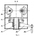
- Figure 5 shows slider-crank mechanism
- Low frequency acoustic converter consists of hollow case 1 with feeding 2 and discharge 3 sections.
- piston exciter 4 is installed and actuated by electromechanical reciprocating drive 5 located in the upper part of the converter above the case 1.
- acoustic energy concentrator 6 is installed in the lower part of case 1 .
- Semi-closed restricted inner volume 7 of acoustic energy concentrator 6 has an ellipsoid inner surface 8 with two focal planes 9 and 10.
- Inner volume 7 of acoustic energy concentrator 6 at one side (top) is vented to cavity 11 of case 1, while at the other (bottom) to cavity 12 of discharge section 3.
- Cavity 11 of case 1 is formed with axisymmetrically located reflecting upper surface 13 of second order and bottom surface 14.
- Upper surface 13 has at least one charging opening 15 in peripheral part, which is vented to feeding section 2.
- the bottom surface 14 of case 1 smoothly passes to ellipsoid inner surface 8 of the inner volume 7 of acoustic energy concentrator 6.
- the upper focal plane 9 of acoustic energy concentrator 6 is matched with focal plane 16 of reflecting surface 13 of second order.
- the bottom focal surface 10 of acoustic energy concentrator 6 is matched with discharge section inlet 3.
- Piston exciter 4 consists of at least one piston 17 connected by means of rod 18 to electromechanical drive 5.
- Piston exciter 4 may, for example, consist of three pistons 17,19 and 20, installed axisymmetrically in cavity 11 of case 1 and connected by rods 18, 21 and 22 to electromechanical reciprocating drive 5.
- Rods 18, 21 and 22 may mutually be tightly bound by links 23 to provide more rigidity.
- Reflecting surface 13 of second order may be shaped in a form of spherical surface and the bottom surface in the form of ellipsoid torus.
- Pistons 17, 19 and 20 may be formed as ellipsoids and with lining 24 on the outer surface.
- Inner surfaces of hollow case 1, acoustic energy concentrator 6 and discharge section 3 are made with lining 25.
- Electromechanical reciprocating drive 5 is preferably to be made in the form of slide-crank mechanism with slider 26 linked by connecting rods 27 with crankshafts 28 supported within the drive case 29 in bearings.
- Crankshafts 28 are bound to each other by means of gear wheels 30 and to electromechanical motors 31 by means of cardan shafts 32.
- Damp material for example sand-and-water pulp, from bin (not shown) through the feeding section 2 and charging opening 15 passes to cavity 11 of case 1.
- After turning electric motors 30 on their rotation is transmitted through cardan shafts 32 to crankshafts 28 of reciprocal mechanism 5 setting in motion connecting rods 27 and slider 26 bound to them.
- slider 26 will make reciprocating motion sliding along stationary guide 33.
- bracket 34 Along with slider 26 reciprocating motion will be committed by tightly bound to it bracket 34 and consequently tightly bound to the latter rods 18, 21 and 22 and pistons 17,19 and 20.
- Two-phase mixture (sand-and-water pulp) begins oscillating and pistons 17,19 and 20 generate low frequency acoustic waves in pulp within the case 1, that reflect from spherical surface 13 and focuse on focal plane 9 of acoustic energy concentrator 6 having inner surface in the form of ellipsoid of revolution.
- the sand-and-water pulp flow within acoustic energy concentrator 6 is subject to pulse action of acoustic energy as a result of its reverberations from inner surface, that makes the action more intensive with better use of energy flow.
- the processed material is discharged through discharge section 3.
- discharge 3 may be closed with gate valve not shown on the drawing.
- the converter being patented let the pulse effect on pulp be increased and output material with greater degree of dispersion be obtained.
Landscapes
- Physics & Mathematics (AREA)
- Engineering & Computer Science (AREA)
- Acoustics & Sound (AREA)
- Signal Processing (AREA)
- Apparatuses For Generation Of Mechanical Vibrations (AREA)
Applications Claiming Priority (2)
| Application Number | Priority Date | Filing Date | Title |
|---|---|---|---|
| RU2001115666/03A RU2191630C1 (ru) | 2001-06-09 | 2001-06-09 | Низкочастотный акустический преобразователь |
| RU2001115666 | 2001-06-09 |
Publications (2)
| Publication Number | Publication Date |
|---|---|
| EP1265456A2 true EP1265456A2 (de) | 2002-12-11 |
| EP1265456A3 EP1265456A3 (de) | 2004-01-21 |
Family
ID=20250526
Family Applications (1)
| Application Number | Title | Priority Date | Filing Date |
|---|---|---|---|
| EP02012719A Withdrawn EP1265456A3 (de) | 2001-06-09 | 2002-06-07 | Niederfrequenz elektroakustischer Wandler |
Country Status (3)
| Country | Link |
|---|---|
| US (1) | US6772962B2 (de) |
| EP (1) | EP1265456A3 (de) |
| RU (1) | RU2191630C1 (de) |
Families Citing this family (3)
| Publication number | Priority date | Publication date | Assignee | Title |
|---|---|---|---|---|
| DE10360526A1 (de) * | 2003-12-22 | 2005-07-14 | Roche Diagnostics Gmbh | Reagenzkassette mit Reagenzbehälter für partikelhaltiges Reagenz für dessen noninvasive Homogenisierung |
| ES2264608B2 (es) * | 2004-09-30 | 2007-08-16 | Universidad De Sevilla | Dispositivo y procedimiento para la atomizacion neumatica de liquidos mediante flujo implosivo de gas. |
| JP2016120161A (ja) * | 2014-12-25 | 2016-07-07 | アクア株式会社 | 洗濯機 |
Family Cites Families (12)
| Publication number | Priority date | Publication date | Assignee | Title |
|---|---|---|---|---|
| US3719168A (en) * | 1971-03-22 | 1973-03-06 | Kadale Equip Co | System for applying uniform layer of a flowable material to a substrate |
| SE416891B (sv) * | 1979-01-04 | 1981-02-16 | Olsson Konsult Ab | Sett och apparat for att oka ett lettflyktigt emnes forgasningshastighet |
| GB2039781A (en) * | 1979-01-04 | 1980-08-20 | Energy & Minerals Res Co | Ultrasonic Wet Grinder |
| US4585167A (en) * | 1982-10-07 | 1986-04-29 | Kholin Boris G | Method for dividing bulk liquid into drops |
| US5152456A (en) * | 1989-12-12 | 1992-10-06 | Bespak, Plc | Dispensing apparatus having a perforate outlet member and a vibrating device |
| US5398816A (en) * | 1993-07-20 | 1995-03-21 | Sweco, Incorporated | Fine mesh screening |
| US5586550A (en) * | 1995-08-31 | 1996-12-24 | Fluid Propulsion Technologies, Inc. | Apparatus and methods for the delivery of therapeutic liquids to the respiratory system |
| US5657926A (en) * | 1995-04-13 | 1997-08-19 | Toda; Kohji | Ultrasonic atomizing device |
| RU2139140C1 (ru) * | 1996-04-09 | 1999-10-10 | Сибирский научно-исследовательский институт механизации и электрификации сельского хозяйства | Диспергатор |
| RU2114698C1 (ru) * | 1997-08-26 | 1998-07-10 | Михаил Тимофеевич Заховаев | Способ разделения суспензий и устройство для его осуществления |
| US6135357A (en) * | 1998-11-23 | 2000-10-24 | General Electric Company | Apparatus for atomizing high-viscosity fluids |
| JP2000079372A (ja) * | 1999-10-08 | 2000-03-21 | Ohbayashi Corp | 土砂分離装置 |
-
2001
- 2001-06-09 RU RU2001115666/03A patent/RU2191630C1/ru not_active IP Right Cessation
-
2002
- 2002-06-06 US US10/162,694 patent/US6772962B2/en not_active Expired - Fee Related
- 2002-06-07 EP EP02012719A patent/EP1265456A3/de not_active Withdrawn
Also Published As
| Publication number | Publication date |
|---|---|
| EP1265456A3 (de) | 2004-01-21 |
| US6772962B2 (en) | 2004-08-10 |
| RU2191630C1 (ru) | 2002-10-27 |
| US20030006184A1 (en) | 2003-01-09 |
Similar Documents
| Publication | Publication Date | Title |
|---|---|---|
| US4758095A (en) | Dual shaft pan mixer | |
| EP0882875B1 (de) | Vorrichtung zum direkten verbinden eines verbrennungsmotors mit einer angetriebenen maschine | |
| US8491222B2 (en) | Vibration tamper for compacting subsoil | |
| CN100354073C (zh) | 发动机式破碎装置 | |
| US6772962B2 (en) | Low frequency acoustic converter | |
| CN102985694A (zh) | 往复式压缩机 | |
| EP2194191A1 (de) | Vibrationsmechanismus für eine Pfahlramme und Pfahlramme | |
| EP0533874A1 (de) | Niederfrequente Vibrationsanordnung. | |
| US4257648A (en) | Non-resonant cyclic drive system employing rectification of the cyclic output | |
| US4800852A (en) | Inline counterbalance weight system for a single cylinder engine | |
| CN222469729U (zh) | 一种振动筛及筛分生产线 | |
| JP4435210B2 (ja) | 回転・往復動装置 | |
| US4201269A (en) | Impact device with linear single acting air spring | |
| RU2176158C2 (ru) | Способ акустической обработки (варианты) и акустическая установка (варианты) | |
| CN214773015U (zh) | 一种混凝土生产过程罐体降噪装置 | |
| RU2615659C1 (ru) | Вибрационный смеситель | |
| US812539A (en) | Gang-saw mill. | |
| RU2615653C1 (ru) | Вибрационный смеситель | |
| EP0245583A2 (de) | Reihen-Unwucht-Ausgleichsvorrichtung für einen Einzylindermotor | |
| JP3827529B2 (ja) | 二つの不平衡重錘体の使用のもとで成形箱内の成形材料を圧縮する振動圧縮装置 | |
| SU1606175A1 (ru) | Смеситель волокнистой суспензии с газообразными реагентами | |
| CN2933611Y (zh) | 惯性振动装置 | |
| CN117563932B (zh) | 一种节能激振器 | |
| SU324789A1 (ru) | Пневматический вибратор | |
| RU2548424C1 (ru) | Вибрационный смеситель |
Legal Events
| Date | Code | Title | Description |
|---|---|---|---|
| PUAI | Public reference made under article 153(3) epc to a published international application that has entered the european phase |
Free format text: ORIGINAL CODE: 0009012 |
|
| AK | Designated contracting states |
Kind code of ref document: A2 Designated state(s): AT BE CH CY DE DK ES FI FR GB GR IE IT LI LU MC NL PT SE TR |
|
| AX | Request for extension of the european patent |
Free format text: AL;LT;LV;MK;RO;SI |
|
| PUAL | Search report despatched |
Free format text: ORIGINAL CODE: 0009013 |
|
| AK | Designated contracting states |
Kind code of ref document: A3 Designated state(s): AT BE CH CY DE DK ES FI FR GB GR IE IT LI LU MC NL PT SE TR |
|
| AX | Request for extension of the european patent |
Extension state: AL LT LV MK RO SI |
|
| 17P | Request for examination filed |
Effective date: 20040623 |
|
| AKX | Designation fees paid |
Designated state(s): BE DE FR GB IT |
|
| GRAP | Despatch of communication of intention to grant a patent |
Free format text: ORIGINAL CODE: EPIDOSNIGR1 |
|
| RIN1 | Information on inventor provided before grant (corrected) |
Inventor name: SERGODEYEV, VLADIMIR VASILYEVICH |
|
| STAA | Information on the status of an ep patent application or granted ep patent |
Free format text: STATUS: THE APPLICATION IS DEEMED TO BE WITHDRAWN |
|
| 18D | Application deemed to be withdrawn |
Effective date: 20060103 |