EP0245583A2 - Reihen-Unwucht-Ausgleichsvorrichtung für einen Einzylindermotor - Google Patents
Reihen-Unwucht-Ausgleichsvorrichtung für einen Einzylindermotor Download PDFInfo
- Publication number
- EP0245583A2 EP0245583A2 EP87101227A EP87101227A EP0245583A2 EP 0245583 A2 EP0245583 A2 EP 0245583A2 EP 87101227 A EP87101227 A EP 87101227A EP 87101227 A EP87101227 A EP 87101227A EP 0245583 A2 EP0245583 A2 EP 0245583A2
- Authority
- EP
- European Patent Office
- Prior art keywords
- crankshaft
- piston
- counterbalance
- engine
- rectilinear path
- Prior art date
- Legal status (The legal status is an assumption and is not a legal conclusion. Google has not performed a legal analysis and makes no representation as to the accuracy of the status listed.)
- Granted
Links
Images


Classifications
-
- F—MECHANICAL ENGINEERING; LIGHTING; HEATING; WEAPONS; BLASTING
- F02—COMBUSTION ENGINES; HOT-GAS OR COMBUSTION-PRODUCT ENGINE PLANTS
- F02B—INTERNAL-COMBUSTION PISTON ENGINES; COMBUSTION ENGINES IN GENERAL
- F02B63/00—Adaptations of engines for driving pumps, hand-held tools or electric generators; Portable combinations of engines with engine-driven devices
- F02B63/02—Adaptations of engines for driving pumps, hand-held tools or electric generators; Portable combinations of engines with engine-driven devices for hand-held tools
-
- F—MECHANICAL ENGINEERING; LIGHTING; HEATING; WEAPONS; BLASTING
- F02—COMBUSTION ENGINES; HOT-GAS OR COMBUSTION-PRODUCT ENGINE PLANTS
- F02B—INTERNAL-COMBUSTION PISTON ENGINES; COMBUSTION ENGINES IN GENERAL
- F02B75/00—Other engines
- F02B75/16—Engines characterised by number of cylinders, e.g. single-cylinder engines
-
- F—MECHANICAL ENGINEERING; LIGHTING; HEATING; WEAPONS; BLASTING
- F16—ENGINEERING ELEMENTS AND UNITS; GENERAL MEASURES FOR PRODUCING AND MAINTAINING EFFECTIVE FUNCTIONING OF MACHINES OR INSTALLATIONS; THERMAL INSULATION IN GENERAL
- F16F—SPRINGS; SHOCK-ABSORBERS; MEANS FOR DAMPING VIBRATION
- F16F15/00—Suppression of vibrations in systems; Means or arrangements for avoiding or reducing out-of-balance forces, e.g. due to motion
- F16F15/22—Compensation of inertia forces
- F16F15/26—Compensation of inertia forces of crankshaft systems using solid masses, other than the ordinary pistons, moving with the system, i.e. masses connected through a kinematic mechanism or gear system
- F16F15/264—Rotating balancer shafts
-
- F—MECHANICAL ENGINEERING; LIGHTING; HEATING; WEAPONS; BLASTING
- F02—COMBUSTION ENGINES; HOT-GAS OR COMBUSTION-PRODUCT ENGINE PLANTS
- F02B—INTERNAL-COMBUSTION PISTON ENGINES; COMBUSTION ENGINES IN GENERAL
- F02B67/00—Engines characterised by the arrangement of auxiliary apparatus not being otherwise provided for, e.g. the apparatus having different functions; Driving auxiliary apparatus from engines, not otherwise provided for
Definitions
- the present invention generally relates to the counter- balancing of a reciprocating piston, internal combustion engine to eliminate imbalance thereof and, more particularly, is concerned with an inline counterbalance weight system for a single cylinder engine which eliminates vibratory imbalance due to piston reciprocation and crankshaft rotation without introducing rocking couple imbalance about the mounting base of the engine.
- a limiting characteristic of a small single cylinder internal combustion engine is the high vibration level created by the engine. Vibrations are inherently generated in such engine, originating from the centerline of its rotating crankshaft and oriented along the line of reciprocating movement of its piston passing through the crankshaft centerline. The vibratory force generated by the engine and transmitted to the operating machine to which the engine is attached and to which it supplies rotary driving power is annoying to the user and can be harmful to the reliability of the machine and shorten its operating life.
- a pair of balancing weights are offset in the same direction from the line of reciprocation of the piston and in opposite directions from the crankshaft.
- the balancing weights are eccentrically mounted on the engine for rotation about axes which extend generally parallel to the crankshaft. Their direction of rotation is opposite to that of a pair of eccentric weight mounted on the crankshaft. While these balancing arrangements substantially counterbalance and eliminate the vibratory force emanating from the centerline of the crankshaft along the line of reciprocation of the piston, they introduce an undesirable rocking couple about the mounting base of the engine.
- the present invention provides an inline counterbalance weight system for a single cylinder engine designed to satisfy the aforementioned needs.
- the system meets its objective of eliminating imbalance motion in the engine by a unique arrangement and configuration of the counterbalance weight in conjunction with the crankshaft and the eccentric weights mounted thereon.
- the arrangement and configuration of the counterbalance weight is one which conserves the volume of additional space needed to accommodate the system by providing a wraparound or nesting relationship between the adjacently positioned rotating components.
- the present invention is directed to the combination in a single cylinder internal combustion engine of: (a) a piston reciprocable in the cylinder along a generally rectilinear path; (b) a main, rotatably mounted crankshaft connected to the piston and rotatably driven in a first rotational direction by the piston about an axis extending generally transverse to and in alignment with the rectilinear path of reciprocation of the piston; (c) weight means eccentrically mounted on the crankshaft; (d) a rotatably mounted counterbalance system extending generally parallel to the crankshaft on an opposite side thereof from the piston and also generally transverse to and in alignment with the rectilinear path of reciprocation of the piston; and (e) means driving the counterbalance system in a second rotational direction opposite to the first rotational direction of the crankshaft and in a predetermined timed relationship thereto.
- vibration imbalance in the engine in the direction of the rectilinear path of reciprocation of the piston is substantially eliminated due to the force vector of the reciprocating piston being generally aligned with and balanced by the force vectors of the rotating counterbalance system and the crankshaft and weight means thereon when the piston is at opposite end positions of its stroke.
- rocking imbalance in the engine is substantially eliminated due to the force vector of the rotating crankshaft and weight means thereon being generally balanced by the force vector of the rotating counterbalance system when the piston is at an intermediate position between the opposite ends of its stroke.
- the counterbalance system includes a rotatably mounted counterbalance shaft extending generally parallel to the crankshaft and transverse to and aligned with the rectilinear path of reciprocation of the piston.
- the counterbalance system includes a counterbalance weight eccentrically mounted on the counterbalance shaft and disposed in symmetrical relationship thereon relative to the rectilinear path of reciprocation of the piston.
- a pair of intermeshing gears interconnect the main and counterbalance shafts and drive the counterbalance shaft in the rotational direction opposite to that of the crankshaft and in the predetermined timed relationship thereto.
- the main crankshaft and the counterbalance shaft are rotated in a one-to-one ratio in the predetermined timed relationship.
- the counterbalance weight has a pair of laterally spaced apart lobes which project toward the crankshaft and overlap with portions thereof during counterrotation of the crankshaft and the counterweight shaft relative to one another.
- the lobes define a peripheral configuration adapted to receive the portions of the crankshaft in a nesting relationship.
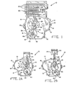
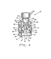
- a single cylinder, reciprocating piston, internal combustion engine generally designated 10, in which is incorporated the inline counterbalance weight system of the present invention, being indicated by the numeral 12.
- the engine 10 includes a crankcase 14 having a peripheral flange 16 with holes 18 formed therein.
- the engine is adapted to be mounted to a machine (not shown), for example the deck of a lawn mower, which will be driven by the rotary power of the engine.
- the single cylinder 20 of the engine 10 is integral with crankcase 14 and is provided with cooling fins 22.
- the engine 10 also includes a cylindrical piston 24, a crankshaft 26 and a connecting rod 28 pivotally interconnecting the piston and crankshaft.
- the piston 24 is adapted to reciprocate within cylinder 20 along a generally rectilinear path extending horizontally and generally parallel to the flange.
- the crankshaft 26 is rotatably mounted at its opposite ends by bearings 30 to the opposite sides 32 of the crankcase 14.
- the connecting rod 28 extends between and pivotally connects a wrist pin 34 in the piston 24 to an eccentric or offset U-shaped arm or throw 36 attached to and extending radially from the crankshaft 26.
- piston 24 As piston 24 reciprocates in cylinder 20, it rotatably drives offset throw 36 and the crankshaft 26, for instance in a clockwise direction as viewed in Figs.
- a pair of spaced weights 38 are eccentrically attached to crankshaft 26 and extend radially therefrom opposite to the offset arm 36 for counterbalancing the eccentrically located mass of the arm 36 and part of the reciprocating masses during rotation of the crankshaft 26. Without the provision of some counterbalancing mechanism, the single cylinder engine 10 with the construction as described will vibrate along the path of reciprocation of piston 24 and in a lateral direction.
- the inline counterbalance weight system 12 of the present invention will effectively eliminate generation of such vibration in the engine 10 and will do so without introducing other equally undesirable imbalance forces.
- the counterbalance weight system 12 includes a counterbalance shaft 40 and a counterbalance weight 42 eccentrically attached on the shaft.
- the counterbalance shaft 40 is rotatably mounted by bearings 44 to the opposite sides 32 of the crankcase 14 so as to extend generally parallel to crankshaft 26 and, along with crankshaft 26, transverse to and in alignment with the rectilinear path of reciprocation of piston 24, the characterization of the system 12 as "inline” derives from the approximately aligned relationship of the counterbalance shaft 40 to crankshaft 26 and the rectilinear path of reciprocation of piston 24, as well as the approximately aligned and symmetrical relationship of the crankshaft offset arm 36 and eccentric weights 38 and the counterbalance weight 42 to the rectilinear path of the piston 24.
- the counterbalance shaft 40 is driven off crankshaft 26 by means in the form of intermeshing gears 46,48 respectively keyed to the crankshaft 26 and counterbalance shaft 40.
- gears 46,48 By the drive connection provided by gears 46,48, counterbalance shaft 40 and weight 42 are rotated about an axis B in a direction counter or opposite, such as counterclockwise in Figs. 2a to 2d, to that of the crankshaft 26 and its offset arm 36 and weights 38.
- the gears 46,48 are in substantially equal in diameter so as to define the timed relationship between respective rotational cycles of the crankshaft 26 and the counterbalance shaftL40 as unity or in a one-to-one ratio.
- Figs. 2a to 2d illustrate the respective successive positions of the piston 24, connecting rod 28, crankshaft offset arm 36 and eccentric weights 38, and counterbalance weight 42 at successive quarter-turns of the crankshaft 26 and counterbalance shaft 40 in one cycle of the engine 10.
- the successive positions of these same components are shown in Figs. 3a to 3d which correspond respectively to those positions shown in Figs. 2a to 2d.
- the piston 24 is approximately halfway along its rectilinear reciprocatory stroke, advancing toward the top dead center (TDC) position thereof.
- Crankshaft weights 38 and counterbalance weight 42 are disposed on opposite sides of their respective rotational axes A,B in opposing relationship such that their force vectors F crank and F cwt , as illustrated in Fig. 5c, are balanced with respect to one another.
- the piston 24 is at the same position as in Figs. 2a and 3a, but is now advancing toward the bottom dead center (BDC) of its stroke.
- the rotating crankshaft weights 38 and counterbalance weight 42 are again disposed in opposing relationship such the their force vectors are balanced with respect to one another, but the positions of the respective weights have been interchanged.
- the piston 24 is at TDC, whereas in Figs. 2d and 3d, it is at BDC.
- the rotating crankshaft weights 38 and the counterbalance weight 42 are disposed on the same sides of their respective rotational axes A,B such that their force vectors are additive with respect to one another and balanced with respect the force vector of the piston.
- the force vectors of the crankshaft weights 38 F crank and counterbalance weight 42 F cwt together balance the force vector F recip of the piston.
- vibration imbalance in the engine 10 in the direction of the rectilinear path of reciprocation of the piston 24 is substantially eliminated.
- This is due to the force vector F recip of the reciprocating piston 24 being generally balanced by the force vectors F crank and F cwt of the rotating counterbalance weight 42 and the crankshaft 26 and weights 38 thereon when the piston 24 is at opposite end positions of its stroke.
- rocking imbalance in the engine 10 is substantially eliminated by the counterbalance system 12.
- This is due to the generally equal displacement of the force vectors F recip , F cwt ,-F crank of the reciprocating piston 24, the counterbalance weight 42 and the crankshaft 26 and weights 38 thereon, as represented in Fig. 5a by distance "a”, and also due to the generally balanced relationship of the force vector of the rotating crankshaft 26 and weights 38 thereon with the force vector of the rotating counterbalance weight 42 when the piston 24 is at an intermediate position between opposite end positions of its stroke.
- the counterbalance weight 42 has a peripheral configuration which allows it to rotate in a nesting relationship with the offset arm 36 of the rotating crankshaft 26. More specifically, the counterbalance weight 42 has a pair of laterally spaced apart lobes 50 which project toward the rotating crankshaft 26 during certain portions of the rotation cycle of the counterbalance shaft 40 and overlap with portions of the rotating offset arm 36. The lobes 50 and the section 52 of the shaft 40 extending therebetween define the peripheral configuration adapted to receive portions of the crankshaft.26 in the wraparound or nesting relationship which minimizes the amount of space required to accommodate the counterbalance system 12 in the engine 10 and brings counterbalance weight 42 more inline with crankshaft weight 38.
Landscapes
- Engineering & Computer Science (AREA)
- General Engineering & Computer Science (AREA)
- Mechanical Engineering (AREA)
- Chemical & Material Sciences (AREA)
- Combustion & Propulsion (AREA)
- Physics & Mathematics (AREA)
- Acoustics & Sound (AREA)
- Aviation & Aerospace Engineering (AREA)
- Shafts, Cranks, Connecting Bars, And Related Bearings (AREA)
- Vibration Prevention Devices (AREA)
- Signal Processing For Digital Recording And Reproducing (AREA)
- Compressors, Vaccum Pumps And Other Relevant Systems (AREA)
Applications Claiming Priority (2)
| Application Number | Priority Date | Filing Date | Title |
|---|---|---|---|
| US86231286A | 1986-05-12 | 1986-05-12 | |
| US862312 | 1986-05-12 |
Publications (3)
| Publication Number | Publication Date |
|---|---|
| EP0245583A2 true EP0245583A2 (de) | 1987-11-19 |
| EP0245583A3 EP0245583A3 (en) | 1989-02-08 |
| EP0245583B1 EP0245583B1 (de) | 1990-07-25 |
Family
ID=25338194
Family Applications (1)
| Application Number | Title | Priority Date | Filing Date |
|---|---|---|---|
| EP19870101227 Expired EP0245583B1 (de) | 1986-05-12 | 1987-01-29 | Reihen-Unwucht-Ausgleichsvorrichtung für einen Einzylindermotor |
Country Status (5)
| Country | Link |
|---|---|
| EP (1) | EP0245583B1 (de) |
| JP (1) | JPS62274132A (de) |
| AU (1) | AU586747B2 (de) |
| CA (1) | CA1272400A (de) |
| DE (1) | DE3763896D1 (de) |
Cited By (4)
| Publication number | Priority date | Publication date | Assignee | Title |
|---|---|---|---|---|
| WO1988006687A1 (en) * | 1987-03-02 | 1988-09-07 | F.L. Smidth & Co. A/S - Maskinfabriken | Vibration compensator apparatus |
| EP0561618A1 (de) * | 1992-03-18 | 1993-09-22 | Videojet Systems International, Inc. | Schwingungsdämpfende Konsole |
| RU2140025C1 (ru) * | 1998-07-06 | 1999-10-20 | Дронов Евгений Анатольевич | Двигатель внутреннего сгорания |
| FR2837890A1 (fr) * | 2002-03-30 | 2003-10-03 | Stihl Ag & Co Kg Andreas | Moteur thermique d'un appareil de travail guide manuellement |
Family Cites Families (4)
| Publication number | Priority date | Publication date | Assignee | Title |
|---|---|---|---|---|
| US2407102A (en) * | 1943-06-04 | 1946-09-03 | Ryder Elmer | Internal-combustion engine |
| USRE28512E (en) * | 1970-10-02 | 1975-08-12 | Reciprocating piston type engines having weights for balancing primary inertial forces | |
| JPS51131863A (en) * | 1975-05-12 | 1976-11-16 | Sugai Kagaku Kogyo Kk | Process for preparation of o-phenylphenol |
| FR2544823B1 (fr) * | 1983-04-21 | 1985-07-12 | Negre Guy | Procede et dispositif d'equilibrage pour une machine rotative a piston |
-
1987
- 1987-01-13 CA CA000527208A patent/CA1272400A/en not_active Expired - Fee Related
- 1987-01-29 DE DE8787101227T patent/DE3763896D1/de not_active Expired - Fee Related
- 1987-01-29 EP EP19870101227 patent/EP0245583B1/de not_active Expired
- 1987-05-01 AU AU72410/87A patent/AU586747B2/en not_active Ceased
- 1987-05-12 JP JP11669287A patent/JPS62274132A/ja active Pending
Cited By (4)
| Publication number | Priority date | Publication date | Assignee | Title |
|---|---|---|---|---|
| WO1988006687A1 (en) * | 1987-03-02 | 1988-09-07 | F.L. Smidth & Co. A/S - Maskinfabriken | Vibration compensator apparatus |
| EP0561618A1 (de) * | 1992-03-18 | 1993-09-22 | Videojet Systems International, Inc. | Schwingungsdämpfende Konsole |
| RU2140025C1 (ru) * | 1998-07-06 | 1999-10-20 | Дронов Евгений Анатольевич | Двигатель внутреннего сгорания |
| FR2837890A1 (fr) * | 2002-03-30 | 2003-10-03 | Stihl Ag & Co Kg Andreas | Moteur thermique d'un appareil de travail guide manuellement |
Also Published As
| Publication number | Publication date |
|---|---|
| CA1272400A (en) | 1990-08-07 |
| JPS62274132A (ja) | 1987-11-28 |
| DE3763896D1 (de) | 1990-08-30 |
| AU7241087A (en) | 1987-11-19 |
| EP0245583B1 (de) | 1990-07-25 |
| AU586747B2 (en) | 1989-07-20 |
| EP0245583A3 (en) | 1989-02-08 |
Similar Documents
| Publication | Publication Date | Title |
|---|---|---|
| US4819593A (en) | Pivoting balancer system | |
| US5282397A (en) | Engine balancing system having at least one pivoting counterbalance weight | |
| US4414934A (en) | Reciprocating piston-type internal combustion engine with improved balancing system | |
| EP1983215A1 (de) | Hubkolbenmaschine und -verbrennungsmotor | |
| US4800852A (en) | Inline counterbalance weight system for a single cylinder engine | |
| US4656981A (en) | Balancing mechanism for reciprocating piston engine | |
| US3861222A (en) | Counterbalanced fixed stroke compressors | |
| CA2471937C (en) | Balance system for single cylinder engine | |
| US6655340B2 (en) | Engine with balancer for second order pitching couple | |
| EP0245583A2 (de) | Reihen-Unwucht-Ausgleichsvorrichtung für einen Einzylindermotor | |
| JPS6330536B2 (de) | ||
| EP0382385A2 (de) | Brennkraftmaschine | |
| WO2002061303A1 (en) | Balancing system using reciprocating counterbalance weight | |
| US5758615A (en) | Arrangement for vibration compensation in a reciprocating-piston internal-combustion engine | |
| JP2010144857A (ja) | 内燃機関におけるバランス装置 | |
| EP0058475A1 (de) | Auswuchten von Motoren | |
| JPH1089002A (ja) | 往復動ピストン機構等のクランク機構 | |
| US7117781B2 (en) | Piston balancing system | |
| JPH0545876Y2 (de) | ||
| GB2191822A (en) | Dynamic balancing of piston and connecting rod assemblies | |
| EP0686236B1 (de) | Hermetischer verdichter mit hin- und hergehenden kolben | |
| GB2058223A (en) | Balancing device for reciprocating machine | |
| JP3554351B2 (ja) | エンジンのバランサ装置 | |
| RU1788301C (ru) | Поршнева машина | |
| GB2263328A (en) | A balanced oscillating mechanism |
Legal Events
| Date | Code | Title | Description |
|---|---|---|---|
| PUAI | Public reference made under article 153(3) epc to a published international application that has entered the european phase |
Free format text: ORIGINAL CODE: 0009012 |
|
| AK | Designated contracting states |
Kind code of ref document: A2 Designated state(s): DE FR GB IT |
|
| PUAL | Search report despatched |
Free format text: ORIGINAL CODE: 0009013 |
|
| AK | Designated contracting states |
Kind code of ref document: A3 Designated state(s): DE FR GB IT |
|
| 17P | Request for examination filed |
Effective date: 19890317 |
|
| 17Q | First examination report despatched |
Effective date: 19890713 |
|
| GRAA | (expected) grant |
Free format text: ORIGINAL CODE: 0009210 |
|
| AK | Designated contracting states |
Kind code of ref document: B1 Designated state(s): DE FR GB IT |
|
| REF | Corresponds to: |
Ref document number: 3763896 Country of ref document: DE Date of ref document: 19900830 |
|
| ET | Fr: translation filed | ||
| ITF | It: translation for a ep patent filed | ||
| PG25 | Lapsed in a contracting state [announced via postgrant information from national office to epo] |
Ref country code: GB Effective date: 19910129 |
|
| PLBE | No opposition filed within time limit |
Free format text: ORIGINAL CODE: 0009261 |
|
| STAA | Information on the status of an ep patent application or granted ep patent |
Free format text: STATUS: NO OPPOSITION FILED WITHIN TIME LIMIT |
|
| 26N | No opposition filed | ||
| GBPC | Gb: european patent ceased through non-payment of renewal fee | ||
| PG25 | Lapsed in a contracting state [announced via postgrant information from national office to epo] |
Ref country code: FR Effective date: 19910930 |
|
| PG25 | Lapsed in a contracting state [announced via postgrant information from national office to epo] |
Ref country code: DE Effective date: 19911001 |
|
| REG | Reference to a national code |
Ref country code: FR Ref legal event code: ST |
|
| PG25 | Lapsed in a contracting state [announced via postgrant information from national office to epo] |
Ref country code: IT Free format text: LAPSE BECAUSE OF NON-PAYMENT OF DUE FEES;WARNING: LAPSES OF ITALIAN PATENTS WITH EFFECTIVE DATE BEFORE 2007 MAY HAVE OCCURRED AT ANY TIME BEFORE 2007. THE CORRECT EFFECTIVE DATE MAY BE DIFFERENT FROM THE ONE RECORDED. Effective date: 20050129 |