EP1264997A1 - Manufacturing process of a sliding bearing having a friction layer - Google Patents
Manufacturing process of a sliding bearing having a friction layer Download PDFInfo
- Publication number
- EP1264997A1 EP1264997A1 EP02291391A EP02291391A EP1264997A1 EP 1264997 A1 EP1264997 A1 EP 1264997A1 EP 02291391 A EP02291391 A EP 02291391A EP 02291391 A EP02291391 A EP 02291391A EP 1264997 A1 EP1264997 A1 EP 1264997A1
- Authority
- EP
- European Patent Office
- Prior art keywords
- layer
- coating
- die
- stick
- bronze
- Prior art date
- Legal status (The legal status is an assumption and is not a legal conclusion. Google has not performed a legal analysis and makes no representation as to the accuracy of the status listed.)
- Granted
Links
Images
Classifications
-
- F—MECHANICAL ENGINEERING; LIGHTING; HEATING; WEAPONS; BLASTING
- F16—ENGINEERING ELEMENTS AND UNITS; GENERAL MEASURES FOR PRODUCING AND MAINTAINING EFFECTIVE FUNCTIONING OF MACHINES OR INSTALLATIONS; THERMAL INSULATION IN GENERAL
- F16C—SHAFTS; FLEXIBLE SHAFTS; ELEMENTS OR CRANKSHAFT MECHANISMS; ROTARY BODIES OTHER THAN GEARING ELEMENTS; BEARINGS
- F16C33/00—Parts of bearings; Special methods for making bearings or parts thereof
- F16C33/02—Parts of sliding-contact bearings
- F16C33/04—Brasses; Bushes; Linings
- F16C33/06—Sliding surface mainly made of metal
- F16C33/14—Special methods of manufacture; Running-in
-
- F—MECHANICAL ENGINEERING; LIGHTING; HEATING; WEAPONS; BLASTING
- F16—ENGINEERING ELEMENTS AND UNITS; GENERAL MEASURES FOR PRODUCING AND MAINTAINING EFFECTIVE FUNCTIONING OF MACHINES OR INSTALLATIONS; THERMAL INSULATION IN GENERAL
- F16C—SHAFTS; FLEXIBLE SHAFTS; ELEMENTS OR CRANKSHAFT MECHANISMS; ROTARY BODIES OTHER THAN GEARING ELEMENTS; BEARINGS
- F16C33/00—Parts of bearings; Special methods for making bearings or parts thereof
- F16C33/02—Parts of sliding-contact bearings
- F16C33/04—Brasses; Bushes; Linings
- F16C33/20—Sliding surface consisting mainly of plastics
- F16C33/201—Composition of the plastic
-
- F—MECHANICAL ENGINEERING; LIGHTING; HEATING; WEAPONS; BLASTING
- F16—ENGINEERING ELEMENTS AND UNITS; GENERAL MEASURES FOR PRODUCING AND MAINTAINING EFFECTIVE FUNCTIONING OF MACHINES OR INSTALLATIONS; THERMAL INSULATION IN GENERAL
- F16C—SHAFTS; FLEXIBLE SHAFTS; ELEMENTS OR CRANKSHAFT MECHANISMS; ROTARY BODIES OTHER THAN GEARING ELEMENTS; BEARINGS
- F16C2220/00—Shaping
- F16C2220/20—Shaping by sintering pulverised material, e.g. powder metallurgy
-
- F—MECHANICAL ENGINEERING; LIGHTING; HEATING; WEAPONS; BLASTING
- F16—ENGINEERING ELEMENTS AND UNITS; GENERAL MEASURES FOR PRODUCING AND MAINTAINING EFFECTIVE FUNCTIONING OF MACHINES OR INSTALLATIONS; THERMAL INSULATION IN GENERAL
- F16C—SHAFTS; FLEXIBLE SHAFTS; ELEMENTS OR CRANKSHAFT MECHANISMS; ROTARY BODIES OTHER THAN GEARING ELEMENTS; BEARINGS
- F16C2223/00—Surface treatments; Hardening; Coating
- F16C2223/30—Coating surfaces
- F16C2223/70—Coating surfaces by electroplating or electrolytic coating, e.g. anodising, galvanising
Definitions
- the present invention relates to a plain bearing provided with a friction coating as well as the production method of said coating.
- High performance plain bearings are required in various fields and in particular in the reducers of high dilution turbojet engine.
- US 3,644,105 describes a bearing comprising a composite copper coating and molybdenum disulphide obtained by co-deposition electrolytic.
- a surface layer consisting of a lead-based alloy containing tin and copper completes the coating.
- a plain bearing especially intended for applications aeronautics such as in turbojet reducers with a high dilution rate conventionally comprises a metal support schematically represented in 1 on the Figure 1.
- the process for producing a coating of friction on a plain bearing according to the invention comprises a preliminary step:
- the next step (b) of said process consists of cleaning ionic vacuum so as to obtain an activation of the layer of sintered bronze.
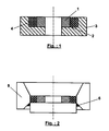
- step (c) apply over the entire bronze surface sintered a layer of about 1mm thick dough PTFE type polytetrafluoroethylene fluoroplastic of molybdenum disulphide and the support 1 coated with the layer 4 of sintered bronze is then placed in a die 5, as schematically shown in Figure 2; then in step (d), the part 1 consisting of the support coated metal is passed through die 5 with addition of a non-stick and resistant coating wear, so as to obtain compression of the dough 5 applied in step (c) in the pores of the bronze layer sintered.
- the coating used can in particular be based on titanium nitride or a coating with equivalent properties such as based on zirconium nitride, chromium or possibly aluminum.
- This coating prevents sintering of the 0 bronze on the tooling and avoids the disadvantages of others previously known products such as graphite which results contamination of the bronze and deteriorates the adhesion of the bronze on the metallic material of the support.
- the same coating is also used in step (a) during sintering for same reasons.
- step (e) the dough is dried, which can for example be carried out at 90 ° C for two hours.
- step (f) a shaping of the bearing part 1 is obtained by a second pass in the die with addition non-stick and anti-wear coating as defined previously. Then we proceed to step (g) sintering of the dough under specified conditions such as at 375 ° C for 40 minutes and the piece is then immersed in the water.
- the plain bearing thus obtained is necessary.
- the qualities of adhesion to the support and the anti-friction qualities of the coating according to the invention thus obtained allow the plain bearing to meet the high performance levels required by its operation.
- the smooth bearing obtained withstands very high pressures which can exceed 50 MPa in the oil film. It can operate at high linear speeds and at temperatures up to 120 ° C. It accepts oil with low viscosity, up to 5x10 -6 m 2 / s at 100 ° C and the bearing is capable of operating without oil for short periods, at reduced loads.
Abstract
Description
La présente invention concerne un palier lisse muni d'un revêtement de frottement ainsi que le procédé de réalisation dudit revêtement.The present invention relates to a plain bearing provided with a friction coating as well as the production method of said coating.
Des paliers lisses à hautes performances sont nécessaires dans divers domaines et notamment dans les réducteurs de turboréacteur à haut taux de dilution.High performance plain bearings are required in various fields and in particular in the reducers of high dilution turbojet engine.
La recherche de hautes performances a conduit à proposer diverses améliorations aux paliers lisses. Ainsi, US 3 644 105 décrit un palier comportant un revêtement composite de cuivre et de bisulfure de molybdène obtenu par co-déposition électrolytique. Une couche superficielle constituée d'un alliage à base de plomb contenant de l'étain et du cuivre complète le revêtement.The search for high performance has led to proposing various improvements to plain bearings. Thus, US 3,644,105 describes a bearing comprising a composite copper coating and molybdenum disulphide obtained by co-deposition electrolytic. A surface layer consisting of a lead-based alloy containing tin and copper completes the coating.
Les solutions connues antérieures ne donnent pas toutefois entière satisfaction et notamment dans les applications notées ci-dessus le besoin subsiste de mettre au point des paliers lisses permettant de bonnes conditions de fonctionnement et une bonne tenue en service dans les conditions sévères d'utilisation correspondantes. Ces conditions comportent notamment une résistance à de très fortes pressions, un fonctionnement à des vitesses linéaires importantes, une résistance à des températures élevées et les paliers lisses doivent également être capables de fonctionner avec une lubrification par une huile à faible viscosité et pendant de courtes périodes sans huile.Previous known solutions do not, however, give complete satisfaction and in particular in the rated applications above the need remains to develop bearings smooth allowing good operating conditions and good service in severe conditions of corresponding use. These conditions include especially resistance to very high pressures, a operation at high linear speeds, a resistance to high temperatures and plain bearings must also be able to operate with a lubrication with low viscosity oil and for short periods without oil.
Ces résultats sont obtenus de manière satisfaisante selon
l'invention par un palier lisse à hautes performances muni
d'un revêtement de frottement caractérisé en ce que le
revêtement comporte une couche de bronze obtenue par frittage
et dont les pores sont remplis d'une pâte fluoroplastique
chargée de bisulfure de molybdène
Ledit revêtement de frottement est obtenu de manière
remarquable conforme à l'invention grâce à un procédé
caractérisé en ce qu'il comporte les étapes suivantes :
Des conditions particulières de réalisation et des paramètres avantageux sont également déterminés.Special conditions of realization and parameters advantageous are also determined.
D'autres caractéristiques et avantages de l'invention seront mieux compris à la lecture de la description qui va suivre d'un exemple de réalisation de l'invention, en référence aux dessins annexés sur lesquels :
- la figure 1 représente selon une vue en coupe longitudinale le support métallique du palier lisse conforme à l'invention lors d'une étape de sa réalisation ;
- la figure 2 représente selon une vue en coupe longitudinale le support métallique du palier lisse conforme à l'invention lors d'une autre étape de sa réalisation.
- Figure 1 shows in a longitudinal sectional view the metal support of the plain bearing according to the invention during a stage of its production;
- 2 shows in a longitudinal sectional view the metal support of the plain bearing according to the invention during another stage of its production.
Un palier lisse notamment destiné à des applications aéronautiques telles que dans les réducteurs de turboréacteur à haut taux de dilution comporte de manière classique un support métallique schématiquement représenté en 1 sur la figure 1. Le procédé de réalisation d'un revêtement de frottement sur un palier lisse conforme à l'invention comporte une étape préalable :A plain bearing especially intended for applications aeronautics such as in turbojet reducers with a high dilution rate conventionally comprises a metal support schematically represented in 1 on the Figure 1. The process for producing a coating of friction on a plain bearing according to the invention comprises a preliminary step:
Comme représenté sur la figure 1, le support métallique 1
ainsi revêtu est ensuite placé dans un conteneur 3, en
ménageant autour du support 1 un réceptacle où est placée de
la poudre de bronze pour la réalisation de l'étape (a) du
procédé conforme à l'invention :
L'étape (b) suivante dudit procédé consiste en un nettoyage ionique sous vide de manière à obtenir une activation de la couche de bronze frittée.The next step (b) of said process consists of cleaning ionic vacuum so as to obtain an activation of the layer of sintered bronze.
A l'étape (c), on applique sur toute la surface de bronze
frittée une couche d'environ 1mm d'épaisseur de pâte
fluoroplastique du type PTFE polytétrafluoroéthylène chargée
de bisulfure de molybdène et le support 1 revêtu de la couche
4 de bronze frittée est ensuite mis en place dans une filière
5, telle que schématiquement représentée sur la figure 2 ;
ensuite à l'étape (d), la pièce 1 constituée du support
métallique revêtu est passée à travers la filière 5 avec
adjonction d'un revêtement anti-adhésif et résistant à
l'usure, de manière à obtenir la compression de la pâte
5 appliquée à l'étape (c) dans les pores de la couche de bronze
frittée. Le revêtement utilisé peut notamment être à base de
nitrure de titane ou un revêtement à propriétés équivalentes
tel qu'à base de nitrure de zirconium, de chrome ou
éventuellement d'aluminium. Ce revêtement évite le frittage du
0 bronze sur l'outillage et évite les inconvénients d'autres
produits précédemment connus tels que le graphite qui entraíne
une contamination du bronze et détériore l'adhérence du bronze
sur le matériau métallique du support. Le même revêtement est
utilisé également à l'étape (a) lors du frittage pour les
mêmes raisons.In step (c), apply over the entire bronze surface
sintered a layer of about 1mm thick dough
PTFE type polytetrafluoroethylene fluoroplastic
of molybdenum disulphide and the support 1 coated with the layer
4 of sintered bronze is then placed in a
A l'étape (e) suivante, on procède à un séchage de la pâte, qui peut par exemple être réalisé à 90 °C pendant deux heures. A l'étape (f) une mise en forme de la pièce 1 de palier est obtenue par un second passage dans la filière avec adjonction du revêtement anti-adhésif et anti-usure tel que défini précédemment. On procède ensuite à l'étape (g) au frittage de la pâte dans des conditions déterminées telles que à 375°C pendant 40 minutes et la pièce est ensuite immergée dans l'eau.In the next step (e), the dough is dried, which can for example be carried out at 90 ° C for two hours. In step (f), a shaping of the bearing part 1 is obtained by a second pass in the die with addition non-stick and anti-wear coating as defined previously. Then we proceed to step (g) sintering of the dough under specified conditions such as at 375 ° C for 40 minutes and the piece is then immersed in the water.
Enfin, à l'étape finale (h) la pièce 1 de palier est passée dans la filière toujours munie du revêtement anti-adhésif pour une mise aux dimensions finales. Finally, at the final stage (h) the bearing part 1 has passed in the sector always provided with the non-stick coating for final dimensions.
Aucune reprise d'usinage du palier lisse ainsi obtenu n'est nécessaire. Les qualités d'adhérence sur le support et les qualités d'anti-friction du revêtement conforme à l'invention ainsi obtenu permettent au palier lisse de satisfaire les hautes performances exigées par son fonctionnement. Notamment, le palier lisse obtenu résiste à de très fortes pressions pouvant dépasser 50 MPa dans le film d'huile. Il peut fonctionner à des vitesses linéaires importantes et à des températures jusqu'à 120°C. Il accepte de l'huile à faible viscosité, jusqu'à 5x10⁻⁶ m2/s à 100°C et le palier est capable de fonctionner sans huile pendant de courtes périodes, à charges réduites.No further machining of the plain bearing thus obtained is necessary. The qualities of adhesion to the support and the anti-friction qualities of the coating according to the invention thus obtained allow the plain bearing to meet the high performance levels required by its operation. In particular, the smooth bearing obtained withstands very high pressures which can exceed 50 MPa in the oil film. It can operate at high linear speeds and at temperatures up to 120 ° C. It accepts oil with low viscosity, up to 5x10 -6 m 2 / s at 100 ° C and the bearing is capable of operating without oil for short periods, at reduced loads.
Claims (4)
Applications Claiming Priority (2)
| Application Number | Priority Date | Filing Date | Title |
|---|---|---|---|
| FR0107414 | 2001-06-07 | ||
| FR0107414A FR2825764B1 (en) | 2001-06-07 | 2001-06-07 | SMOOTH BEARING PROVIDED WITH A FRICTION COATING AND METHOD FOR PRODUCING THE SAME |
Publications (2)
| Publication Number | Publication Date |
|---|---|
| EP1264997A1 true EP1264997A1 (en) | 2002-12-11 |
| EP1264997B1 EP1264997B1 (en) | 2005-08-31 |
Family
ID=8864030
Family Applications (1)
| Application Number | Title | Priority Date | Filing Date |
|---|---|---|---|
| EP02291391A Expired - Lifetime EP1264997B1 (en) | 2001-06-07 | 2002-06-06 | Manufacturing process of a sliding bearing having a friction layer |
Country Status (8)
| Country | Link |
|---|---|
| US (1) | US7033529B2 (en) |
| EP (1) | EP1264997B1 (en) |
| JP (1) | JP2004522108A (en) |
| CA (1) | CA2449128C (en) |
| DE (1) | DE60205811T2 (en) |
| FR (1) | FR2825764B1 (en) |
| UA (1) | UA75153C2 (en) |
| WO (1) | WO2002099297A2 (en) |
Families Citing this family (2)
| Publication number | Priority date | Publication date | Assignee | Title |
|---|---|---|---|---|
| DE102004061097A1 (en) * | 2004-12-18 | 2006-06-22 | Schaeffler Kg | End profiling on plain bearing counterpart partners to reduce surface pressure |
| US8240923B2 (en) * | 2008-01-15 | 2012-08-14 | The Timken Company | X-ray tube rotating anode assembly bearing |
Citations (4)
| Publication number | Priority date | Publication date | Assignee | Title |
|---|---|---|---|---|
| GB2185697A (en) * | 1986-01-27 | 1987-07-29 | Glyco Metall Werke | Multi-layer composite material |
| US5780396A (en) * | 1995-02-01 | 1998-07-14 | Daido Metal Company Ltd. | Sliding member |
| GB2321676A (en) * | 1997-01-29 | 1998-08-05 | Glacier Vandervell Ltd | Bearing assembly and method |
| US6178639B1 (en) * | 1998-05-01 | 2001-01-30 | Federal-Mogul World Wide, Inc. | Multi-layer engine bearings and method of manufacture |
Family Cites Families (18)
| Publication number | Priority date | Publication date | Assignee | Title |
|---|---|---|---|---|
| US3644105A (en) | 1970-03-03 | 1972-02-22 | Clevite Corp | Multilayer bearing |
| JPS59103022A (en) * | 1982-12-03 | 1984-06-14 | Daido Metal Kogyo Kk | Bearing material having superior wearing resistance |
| GB2172296B (en) * | 1985-03-15 | 1988-07-06 | Ae Plc | Plain bearing material incorporating polytetrafluoroethylene and plain bearings incorporating such a material |
| JPS639906A (en) * | 1986-07-01 | 1988-01-16 | Seiko Instr & Electronics Ltd | Magnet |
| JPH01219076A (en) * | 1988-02-26 | 1989-09-01 | Honda Motor Co Ltd | Production of ceramic sliding material |
| JPH0735513B2 (en) * | 1990-02-27 | 1995-04-19 | 大同メタル工業株式会社 | Sliding member and manufacturing method thereof |
| JP2501703B2 (en) * | 1992-01-14 | 1996-05-29 | 大同メタル工業株式会社 | Composite sliding member |
| JP3295968B2 (en) * | 1992-06-10 | 2002-06-24 | 株式会社豊田中央研究所 | Method for producing a material having a hard low friction layer on the surface |
| JPH06173944A (en) * | 1992-12-03 | 1994-06-21 | Ebara Corp | Gas dynamic pressure bearing |
| JP2925430B2 (en) * | 1993-06-08 | 1999-07-28 | 株式会社リケン | Sliding member |
| JP3949183B2 (en) * | 1994-05-23 | 2007-07-25 | オイレス工業株式会社 | Resin composition for sliding member and sliding member using the same |
| JP3755932B2 (en) * | 1996-06-13 | 2006-03-15 | 株式会社小松製作所 | Sliding material and manufacturing method thereof |
| EP0852298B1 (en) * | 1996-12-14 | 2003-03-19 | Federal-Mogul Deva GmbH | Journal bearing material and method for manufacturing the same |
| EP0956459A1 (en) * | 1997-01-29 | 1999-11-17 | Dana Corporation | Bearing assembly and manufacturing method |
| JPH10244543A (en) * | 1997-03-04 | 1998-09-14 | Sumitomo Metal Mining Co Ltd | Mold fitted with abrasion-resistant durable hard coating film |
| GB9713079D0 (en) * | 1997-06-21 | 1997-08-27 | T & N Technology Ltd | Manufacture of plain bearings |
| JP3782869B2 (en) * | 1997-07-01 | 2006-06-07 | 株式会社大和化成研究所 | Tin-silver alloy plating bath |
| JP3675658B2 (en) * | 1999-02-09 | 2005-07-27 | 日本科学冶金株式会社 | bearing |
-
2001
- 2001-06-07 FR FR0107414A patent/FR2825764B1/en not_active Expired - Fee Related
-
2002
- 2002-06-06 JP JP2003502385A patent/JP2004522108A/en active Pending
- 2002-06-06 WO PCT/FR2002/001927 patent/WO2002099297A2/en active Application Filing
- 2002-06-06 US US10/478,691 patent/US7033529B2/en not_active Expired - Fee Related
- 2002-06-06 UA UA2004010110A patent/UA75153C2/en unknown
- 2002-06-06 CA CA002449128A patent/CA2449128C/en not_active Expired - Fee Related
- 2002-06-06 DE DE60205811T patent/DE60205811T2/en not_active Expired - Fee Related
- 2002-06-06 EP EP02291391A patent/EP1264997B1/en not_active Expired - Lifetime
Patent Citations (4)
| Publication number | Priority date | Publication date | Assignee | Title |
|---|---|---|---|---|
| GB2185697A (en) * | 1986-01-27 | 1987-07-29 | Glyco Metall Werke | Multi-layer composite material |
| US5780396A (en) * | 1995-02-01 | 1998-07-14 | Daido Metal Company Ltd. | Sliding member |
| GB2321676A (en) * | 1997-01-29 | 1998-08-05 | Glacier Vandervell Ltd | Bearing assembly and method |
| US6178639B1 (en) * | 1998-05-01 | 2001-01-30 | Federal-Mogul World Wide, Inc. | Multi-layer engine bearings and method of manufacture |
Also Published As
| Publication number | Publication date |
|---|---|
| UA75153C2 (en) | 2006-03-15 |
| EP1264997B1 (en) | 2005-08-31 |
| WO2002099297A2 (en) | 2002-12-12 |
| CA2449128A1 (en) | 2002-12-12 |
| WO2002099297A3 (en) | 2003-02-13 |
| FR2825764A1 (en) | 2002-12-13 |
| CA2449128C (en) | 2009-06-02 |
| FR2825764B1 (en) | 2003-09-19 |
| DE60205811T2 (en) | 2006-06-08 |
| US20050047949A1 (en) | 2005-03-03 |
| JP2004522108A (en) | 2004-07-22 |
| DE60205811D1 (en) | 2005-10-06 |
| US7033529B2 (en) | 2006-04-25 |
Similar Documents
| Publication | Publication Date | Title |
|---|---|---|
| US9816613B2 (en) | Coated sliding element | |
| US20110142384A1 (en) | Sliding element having a multiple layer | |
| GB2345095A (en) | Sliding bearing including a resin layer consisting of soft metal particles dispersed in a thermosetting resin | |
| EP1832753A2 (en) | Structure providing an interface between two moving mechanical parts, manufacturing method and application to vacuum pumps | |
| EP1264997B1 (en) | Manufacturing process of a sliding bearing having a friction layer | |
| FR3089523A1 (en) | Method for manufacturing a coating of a metal matrix composite material on a part for a motor vehicle | |
| JP6560107B2 (en) | Sliding member | |
| EP1875092A2 (en) | Pair of guiding element of which on is made of a specific steel leading to improved anti-seizing performances | |
| EP4001460A1 (en) | Method for depositing a coating on a bore of a mechanical part by cold spray method | |
| EP0237448A1 (en) | Work pieces made of aluminium or its alloys, and of which at least one face presents at least one zone region resistant to wear | |
| US7281853B2 (en) | Bearing material | |
| EP3973202B1 (en) | Member for guiding a mobile element in oscillation or rotation | |
| FR3097785A1 (en) | Contact layer on the surface of a metal member in relative motion against another metal member, and a hinge connection provided with such a contact layer | |
| EP3586045B1 (en) | Movement transmission device for a combustion engine | |
| FR3066576A1 (en) | IMPROVED MOTION TRANSMISSION DEVICE FOR THERMAL MOTOR | |
| FR3045736B1 (en) | HYDRAULIC DEVICE COMPRISING A CERAMIC COATING | |
| RU2267034C2 (en) | Method of producing slide bearing | |
| FR3123397A1 (en) | Plain bearing with coated outer and inner rings | |
| Ajayi et al. | Effect of metallic coating properties on the tribology of oil-lubricated coated-ceramics | |
| FR3123012A1 (en) | SURFACE TREATMENT METHOD OF A PISTON ROD | |
| EP1160495A1 (en) | Sealing member for flow control valve | |
| WO2019097171A1 (en) | Self-lubricating ring for fluid bearing and method for manufacturing such a ring | |
| CH474700A (en) | Sliding body | |
| EP1486582A1 (en) | Low friction Micromechanical device | |
| CH476235A (en) | Sliding body |
Legal Events
| Date | Code | Title | Description |
|---|---|---|---|
| PUAI | Public reference made under article 153(3) epc to a published international application that has entered the european phase |
Free format text: ORIGINAL CODE: 0009012 |
|
| 17P | Request for examination filed |
Effective date: 20020613 |
|
| AK | Designated contracting states |
Kind code of ref document: A1 Designated state(s): AT BE CH CY DE DK ES FI FR GB GR IE IT LI LU MC NL PT SE TR |
|
| AX | Request for extension of the european patent |
Free format text: AL;LT;LV;MK;RO;SI |
|
| AKX | Designation fees paid |
Designated state(s): DE FR GB IT |
|
| GRAP | Despatch of communication of intention to grant a patent |
Free format text: ORIGINAL CODE: EPIDOSNIGR1 |
|
| GRAS | Grant fee paid |
Free format text: ORIGINAL CODE: EPIDOSNIGR3 |
|
| GRAA | (expected) grant |
Free format text: ORIGINAL CODE: 0009210 |
|
| AK | Designated contracting states |
Kind code of ref document: B1 Designated state(s): DE FR GB IT |
|
| REG | Reference to a national code |
Ref country code: GB Ref legal event code: FG4D Free format text: NOT ENGLISH |
|
| GBT | Gb: translation of ep patent filed (gb section 77(6)(a)/1977) |
Effective date: 20050831 |
|
| REF | Corresponds to: |
Ref document number: 60205811 Country of ref document: DE Date of ref document: 20051006 Kind code of ref document: P |
|
| PLBE | No opposition filed within time limit |
Free format text: ORIGINAL CODE: 0009261 |
|
| STAA | Information on the status of an ep patent application or granted ep patent |
Free format text: STATUS: NO OPPOSITION FILED WITHIN TIME LIMIT |
|
| 26N | No opposition filed |
Effective date: 20060601 |
|
| PGFP | Annual fee paid to national office [announced via postgrant information from national office to epo] |
Ref country code: IT Payment date: 20090527 Year of fee payment: 8 |
|
| PGFP | Annual fee paid to national office [announced via postgrant information from national office to epo] |
Ref country code: DE Payment date: 20090703 Year of fee payment: 8 Ref country code: GB Payment date: 20090526 Year of fee payment: 8 |
|
| GBPC | Gb: european patent ceased through non-payment of renewal fee |
Effective date: 20100606 |
|
| PG25 | Lapsed in a contracting state [announced via postgrant information from national office to epo] |
Ref country code: IT Free format text: LAPSE BECAUSE OF NON-PAYMENT OF DUE FEES Effective date: 20100606 |
|
| PG25 | Lapsed in a contracting state [announced via postgrant information from national office to epo] |
Ref country code: DE Free format text: LAPSE BECAUSE OF NON-PAYMENT OF DUE FEES Effective date: 20110101 |
|
| PG25 | Lapsed in a contracting state [announced via postgrant information from national office to epo] |
Ref country code: GB Free format text: LAPSE BECAUSE OF NON-PAYMENT OF DUE FEES Effective date: 20100606 |
|
| REG | Reference to a national code |
Ref country code: FR Ref legal event code: PLFP Year of fee payment: 15 |
|
| REG | Reference to a national code |
Ref country code: FR Ref legal event code: PLFP Year of fee payment: 16 |
|
| REG | Reference to a national code |
Ref country code: FR Ref legal event code: CD Owner name: HISPANO SUIZA Effective date: 20170725 |
|
| REG | Reference to a national code |
Ref country code: FR Ref legal event code: PLFP Year of fee payment: 17 |
|
| PGFP | Annual fee paid to national office [announced via postgrant information from national office to epo] |
Ref country code: FR Payment date: 20210519 Year of fee payment: 20 |