EP1264973A2 - Procédé de combustion dans un moteur Diesel et procédé permettant d'ébaucher un moteur Diesel - Google Patents
Procédé de combustion dans un moteur Diesel et procédé permettant d'ébaucher un moteur Diesel Download PDFInfo
- Publication number
- EP1264973A2 EP1264973A2 EP02012335A EP02012335A EP1264973A2 EP 1264973 A2 EP1264973 A2 EP 1264973A2 EP 02012335 A EP02012335 A EP 02012335A EP 02012335 A EP02012335 A EP 02012335A EP 1264973 A2 EP1264973 A2 EP 1264973A2
- Authority
- EP
- European Patent Office
- Prior art keywords
- fuel
- cavity
- lip portion
- spray
- diesel engine
- Prior art date
- Legal status (The legal status is an assumption and is not a legal conclusion. Google has not performed a legal analysis and makes no representation as to the accuracy of the status listed.)
- Granted
Links
Images


Classifications
-
- F—MECHANICAL ENGINEERING; LIGHTING; HEATING; WEAPONS; BLASTING
- F02—COMBUSTION ENGINES; HOT-GAS OR COMBUSTION-PRODUCT ENGINE PLANTS
- F02B—INTERNAL-COMBUSTION PISTON ENGINES; COMBUSTION ENGINES IN GENERAL
- F02B23/00—Other engines characterised by special shape or construction of combustion chambers to improve operation
- F02B23/02—Other engines characterised by special shape or construction of combustion chambers to improve operation with compression ignition
- F02B23/06—Other engines characterised by special shape or construction of combustion chambers to improve operation with compression ignition the combustion space being arranged in working piston
- F02B23/0672—Omega-piston bowl, i.e. the combustion space having a central projection pointing towards the cylinder head and the surrounding wall being inclined towards the cylinder center axis
-
- F—MECHANICAL ENGINEERING; LIGHTING; HEATING; WEAPONS; BLASTING
- F02—COMBUSTION ENGINES; HOT-GAS OR COMBUSTION-PRODUCT ENGINE PLANTS
- F02B—INTERNAL-COMBUSTION PISTON ENGINES; COMBUSTION ENGINES IN GENERAL
- F02B23/00—Other engines characterised by special shape or construction of combustion chambers to improve operation
- F02B23/02—Other engines characterised by special shape or construction of combustion chambers to improve operation with compression ignition
- F02B23/06—Other engines characterised by special shape or construction of combustion chambers to improve operation with compression ignition the combustion space being arranged in working piston
- F02B23/0618—Other engines characterised by special shape or construction of combustion chambers to improve operation with compression ignition the combustion space being arranged in working piston having in-cylinder means to influence the charge motion
- F02B23/0621—Squish flow
-
- F—MECHANICAL ENGINEERING; LIGHTING; HEATING; WEAPONS; BLASTING
- F02—COMBUSTION ENGINES; HOT-GAS OR COMBUSTION-PRODUCT ENGINE PLANTS
- F02B—INTERNAL-COMBUSTION PISTON ENGINES; COMBUSTION ENGINES IN GENERAL
- F02B23/00—Other engines characterised by special shape or construction of combustion chambers to improve operation
- F02B23/02—Other engines characterised by special shape or construction of combustion chambers to improve operation with compression ignition
- F02B23/06—Other engines characterised by special shape or construction of combustion chambers to improve operation with compression ignition the combustion space being arranged in working piston
- F02B23/0618—Other engines characterised by special shape or construction of combustion chambers to improve operation with compression ignition the combustion space being arranged in working piston having in-cylinder means to influence the charge motion
- F02B23/0624—Swirl flow
-
- F—MECHANICAL ENGINEERING; LIGHTING; HEATING; WEAPONS; BLASTING
- F02—COMBUSTION ENGINES; HOT-GAS OR COMBUSTION-PRODUCT ENGINE PLANTS
- F02B—INTERNAL-COMBUSTION PISTON ENGINES; COMBUSTION ENGINES IN GENERAL
- F02B23/00—Other engines characterised by special shape or construction of combustion chambers to improve operation
- F02B23/02—Other engines characterised by special shape or construction of combustion chambers to improve operation with compression ignition
- F02B23/06—Other engines characterised by special shape or construction of combustion chambers to improve operation with compression ignition the combustion space being arranged in working piston
- F02B23/0645—Details related to the fuel injector or the fuel spray
- F02B23/0648—Means or methods to improve the spray dispersion, evaporation or ignition
- F02B23/0651—Means or methods to improve the spray dispersion, evaporation or ignition the fuel spray impinging on reflecting surfaces or being specially guided throughout the combustion space
-
- F—MECHANICAL ENGINEERING; LIGHTING; HEATING; WEAPONS; BLASTING
- F02—COMBUSTION ENGINES; HOT-GAS OR COMBUSTION-PRODUCT ENGINE PLANTS
- F02B—INTERNAL-COMBUSTION PISTON ENGINES; COMBUSTION ENGINES IN GENERAL
- F02B2275/00—Other engines, components or details, not provided for in other groups of this subclass
- F02B2275/14—Direct injection into combustion chamber
-
- F—MECHANICAL ENGINEERING; LIGHTING; HEATING; WEAPONS; BLASTING
- F02—COMBUSTION ENGINES; HOT-GAS OR COMBUSTION-PRODUCT ENGINE PLANTS
- F02B—INTERNAL-COMBUSTION PISTON ENGINES; COMBUSTION ENGINES IN GENERAL
- F02B23/00—Other engines characterised by special shape or construction of combustion chambers to improve operation
- F02B23/02—Other engines characterised by special shape or construction of combustion chambers to improve operation with compression ignition
- F02B23/06—Other engines characterised by special shape or construction of combustion chambers to improve operation with compression ignition the combustion space being arranged in working piston
- F02B23/0645—Details related to the fuel injector or the fuel spray
- F02B23/0669—Details related to the fuel injector or the fuel spray having multiple fuel spray jets per injector nozzle
-
- F—MECHANICAL ENGINEERING; LIGHTING; HEATING; WEAPONS; BLASTING
- F02—COMBUSTION ENGINES; HOT-GAS OR COMBUSTION-PRODUCT ENGINE PLANTS
- F02B—INTERNAL-COMBUSTION PISTON ENGINES; COMBUSTION ENGINES IN GENERAL
- F02B3/00—Engines characterised by air compression and subsequent fuel addition
- F02B3/06—Engines characterised by air compression and subsequent fuel addition with compression ignition
-
- F—MECHANICAL ENGINEERING; LIGHTING; HEATING; WEAPONS; BLASTING
- F02—COMBUSTION ENGINES; HOT-GAS OR COMBUSTION-PRODUCT ENGINE PLANTS
- F02F—CYLINDERS, PISTONS OR CASINGS, FOR COMBUSTION ENGINES; ARRANGEMENTS OF SEALINGS IN COMBUSTION ENGINES
- F02F1/00—Cylinders; Cylinder heads
- F02F1/24—Cylinder heads
- F02F2001/244—Arrangement of valve stems in cylinder heads
- F02F2001/247—Arrangement of valve stems in cylinder heads the valve stems being orientated in parallel with the cylinder axis
-
- Y—GENERAL TAGGING OF NEW TECHNOLOGICAL DEVELOPMENTS; GENERAL TAGGING OF CROSS-SECTIONAL TECHNOLOGIES SPANNING OVER SEVERAL SECTIONS OF THE IPC; TECHNICAL SUBJECTS COVERED BY FORMER USPC CROSS-REFERENCE ART COLLECTIONS [XRACs] AND DIGESTS
- Y02—TECHNOLOGIES OR APPLICATIONS FOR MITIGATION OR ADAPTATION AGAINST CLIMATE CHANGE
- Y02T—CLIMATE CHANGE MITIGATION TECHNOLOGIES RELATED TO TRANSPORTATION
- Y02T10/00—Road transport of goods or passengers
- Y02T10/10—Internal combustion engine [ICE] based vehicles
- Y02T10/12—Improving ICE efficiencies
Definitions
- the present invention relates to diesel engines, fuel combustion methods for diesel engines and methods for designing a diesel engine.
- Direct-injection diesel engines in which the top portion of the piston is provided with a reentrant-type cavity are well known in the art.
- JP H09-41975A discloses that by setting the cavity shape such that fuel injected toward the lip portion of the piston is detached from the cavity side wall when it moves from the lip portion toward the bottom portion of the cavity, the mixing of the fuel spray with air can be improved, and the generation of smoke can be suppressed.
- the amount of NOx generated grows as the temperature of the air-fuel mixture increases and as the combustion time of the air-fuel temperature increases. That is to say, when there are heat spots (local high temperature regions) in the combustion chambers over a long time, the NOx increases.
- the present invention decreases and evades the amount of NOx generated by striving for an early dispersion of such heat spots.
- the amount of soot generated increases when combustion takes place while the fuel is insufficiently mixed with air, Also, when the mixture between the combustion gas and air during the later half of the combustion is insufficient, the oxidation of soot does not proceed, and as a result the amount of soot exhausted becomes large.
- the present invention suppresses the generation of soot by promoting the mixture of the fuel spray and air, thus raising the utilization ratio of air in the latter half of the combustion to enhance the oxidation of soot, and decreasing and evading the amount of soot exhausted.
- the present inventors studied mechanisms for creating a vertical vortex in a reentrant-type cavity of a piston top portion, and tried to intensify the vertical vortex with an approach that is different from the related art.
- the vertical vortex in the cavity is created during the compression stroke, and the fuel spray is sucked into it, but in accordance with the present invention, a relatively concentrated fuel vapor region is formed near the lip portion during the ignition lag time, and the creation/intensification of the vertical vortex is achieved by guiding this fuel vapor with an expansive flow of combustion gas after igniting the fuel vapor toward the bottom of the cavity.
- a method for fuel combustion in a diesel engine in which a reentrant-type cavity whose diameter becomes smaller towards an aperture edge is provided at a top portion of a piston includes the steps of:
- the present invention utilizes the expansive flow of the combustion gas to guide the fuel vapor from the vicinity of the lip portion to the bottom of the cavity, thereby achieving a dispersion or shifting of heat spots.
- a vertical vortex is formed in the compression stroke, and the fuel spray injected toward a location below the lip portion is sucked into the vertical vortex, so that the fuel spray is slowly dispersed toward the bottom of the cavity by the vertical vortex during the ignition lag time. Therefore, an accumulation of fuel vapor that is appropriate for ignition cannot be achieved near the lip portion, and ignition tends to occur at a location downstream in the vertical vortex where fuel vapor has accumulated.
- the expansive flow of combustion gas caused by the ignition spreads not only in the downstream direction of the vertical vortex but also in the upstream direction, thus weakening the intensity of the expansive flow, so that the effect of the fuel vapor hitting the wall surrounding the cavity and being guided to the bottom of the cavity is weak, and the contribution to the intensification of the vertical vortex is not that large after all. So, even though a vertical vortex is created during the compression stroke, a strong vertical vortex is not attained.
- the fuel spray reaches the lip portion during the ignition lag time and a fuel vapor region is formed near the lip portion.
- the ignition position (ignition point) of the fuel spray is located upstream from the concentrated fuel vapor, so that the combustion spreads in a direction towards the downstream side. Therefore, a strong expansive flow is generated. It should be noted that the reason why the ignition point is located on the upstream side is because an intensive vertical vortex is not formed at the compression stroke, and it appears that the fuel becomes too rich near the lip portion and a location with a concentration suitable for ignition is somewhat removed from the lip portion.
- the combustion gas due to the expansive flow of the combustion gas after igniting the fuel vapor near the lip portion, the combustion gas is driven against the wall surrounding the cavity (in particular the border region between the lip portion and the portion that is caved outward from the lip portion in the direction of the piston diameter), and guided to the bottom of the cavity, and a unidirectional intensive expansive flow is created, which propagates the flame over the fuel guided to the bottom of the cavity, further augmenting the vertical vortex. That is to say, one difference to the related art is that the expansive flow of combustion gas is actively utilized to guide fuel vapor to the cavity bottom.
- a diesel engine in accordance with the present invention includes:
- the fuel spray reaches the lip portion in the ignition lag time.
- the inside of the cavity is hot, so that the vaporization of'the fuel spray proceeds simultaneously with the mixing of the fuel spray and air, and fuel vapor is formed near the lip portion.
- the ignition occurs at a location where the fuel vapor and the air have mixed and the ignition conditions are met within the combustible air-fuel mixture, so that it does not occur at the front end of the spray (near the lip portion) or near the fuel ignition valve, but normally at a location that is somewhat removed in injection direction from the fuel injector (but also removed from the lip portion).
- the liquid jet of fuel injected with the fuel injector is not sufficiently dissociated before it reaches the lip portion, so that it forms an incomplete spray, and consequently also the formation of the fuel vapor is insufficient, so that the expansive flow of the combustion gas does not act efficiently.
- the core of the fuel spray that is, the liquid column in the fuel spray injected from the fuel injector or a portion where the fuel concentration is extremely high
- the value of k is larger than 1.8, that is, when Dlip becomes relatively too large, then the distance from the ignition point to the lip portion becomes too long, so that even though the expansive flow of the combustion gas caused by the ignition acts on the fuel vapor in front of it, a large amount of fuel vapor disperses to the environs before it is driven against the lip portion.
- the expansive flow does not act efficiently to guide the fuel vapor toward the cavity bottom, and the amount of NOx generated increases.
- the value of k is 1.5 to 1.7.
- the cone angle ⁇ of the fuel spray of the fuel injector is 153 ° to 157°.
- the fuel injection is ordinarily carried out near the dead point of the compression stroke, and in particular, at a CA of several degrees (for example 2° ATDC) after the upper dead point.
- the cone angle ⁇ is less than 153°, the fuel spray is driven towards the bottom of the cavity without hitting the lip portion, and a sufficient dispersion/shifting or early extinguishing of heat spots utilizing the vertical vortex due to the above-described expansive flow is not achieved. That is to say, fuel does not accumulate at the lip portion so that the expansive flow is weak, and therefore also the vertical vortex is weak.
- the cone angle ⁇ is greater than 157°, then the fuel spray injected from the fuel injector is directed toward the squish area of around the aperture of the cavity, and the fuel spray tends to combust incompletely, since this squish area tends to dissipate heat to the cylinder head and the cylinder block, leading to an increase of the soot generated. Consequently, in this regard, it is even more preferable that the cone angle ⁇ is 154° to 156°.
- the value of K is set to 1.8 to 2.5, and it is even preferable to set the value to K to 2.0 to 2.3.
- the spray angle ⁇ of the fuel spray is 15° to 24°.
- the spray angle ⁇ is 15° to 24°, and more preferably 18° to 23°.
- the fuel injection pressure of the fuel injector is at least 50 MPa.
- the fuel injection pressure is at least 50 MPa. More preferably, the fuel injection pressure is at least 80 MPa.
- a center portion of the cavity of the piston protrudes upward, such that combustion gas that has moved from the lip portion to the bottom is guided toward the aperture portion at the center of the cavity.
- a ratio of a swirl momentum to a fuel spray momentum at the lip portion at a time when the fuel spray injected with the fuel injector first reaches the lip portion of the cavity of the piston is 0.9 to 1.5.
- the swirl occurring in the bore at the intake stroke contributes to the reduction of the generated amount of soot by enhancing the mixing of the fuel spray or fuel vapor with air in the combustion stroke (expansion stroke).
- the swirl is too strong, the penetration of the fuel spray becomes small, which is disadvantageous with regard to the after-burning of soot utilizing the vertical vortex caused by the expansive flow of the combustion gas.
- the momentum ratio is set to 0.9 to 1.5. It is even more preferable that the momentum ratio is 1.1 to 1.3.
- a method for designing a diesel engine includes:
- an engine utilizing the above-described expansive flow of the combustion gas, an engine can be designed, in which the dispersion/shifting or early extinguishing of heat spots can be achieved.
- Fig. 1 is a cross-sectional view showing the structure of a diesel engine in accordance with an embodiment of the present invention.
- Figs. 2A and 2B are diagrams (cross-sectional views) illustrating the combustion concept of the present invention.
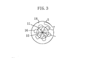
- Fig. 3 is a top view of the combustion chamber illustrating the cross-sectional position of Figs. 4 to 10 .
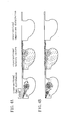
- Figs. 4A and 4B are diagrams illustrating the cross-sectional fuel distribution, the cross-sectional velocity vectors and the cross-sectional temperature distribution at 6° ATDC determined by simulation for spray angles of 22° and 30°.
- Figs. 5A and 5B are diagrams illustrating the cross-sectional fuel distribution, the cross-sectional velocity vectors and the cross-sectional temperature distribution at 8° ATDC determined by simulation for spray angles of 22° and 30°.
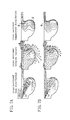
- Figs. 6A and 6B are diagrams illustrating the cross-sectional fuel distribution, the cross-sectional velocity vectors and the cross-sectional temperature distribution at 10° ATDC determined by simulation for spray angles of 22° and 30°.
- Figs. 7A and 7B are diagrams illustrating the cross-sectional fuel distribution, the cross-sectional velocity vectors and the cross-sectional temperature distribution at 12° ATDC determined by simulation for spray angles of 22° and 30°.
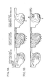
- Figs. 8A and 8B are diagrams illustrating the cross-sectional fuel distribution, the cross-sectional velocity vectors and the cross-sectional temperature distribution at 14° ATDC determined by simulation for spray angles of 22° and 30°.
- Figs. 9A and 9B are diagrams illustrating the cross-sectional fuel distribution, the cross-sectional velocity vectors and the cross-sectional temperature distribution at 16° ATDC determined by simulation for spray angles of 22° and 30°.
- Figs. 10A and 10B are diagrams illustrating the cross-sectional fuel distribution, the cross-sectional velocity vectors and the cross-sectional temperature distribution at 18° ATDC determined by simulation for spray angles of 22° and 30°.
- Fig. 11 is a graph illustrating the relationship between the nozzle hole diameter and the spray angle ⁇ .
- Fig. 12 is a graph illustrating the relationship between the nozzle hole diameter and the spray travel distance (penetration) Sp.
- Fig. 13 is a graph illustrating the relationship between the value of k and the generated amount of NO.
- Fig. 14 is a graph showing the amount of soot exhausted for various values of the ratio of the swirl momentum to the fuel spray momentum.
- Fig. 15 is a graph showing the relationship between the spray angle ⁇ and the EGR ratio to the exhausted amount of NOx and the exhausted amount of soot.
- numeral 1 denotes a piston
- numeral 2 denotes a cylinder block
- numeral 3 denotes a cylinder head
- numeral 4 denotes an intake port (helical port)
- numeral 5 denotes an exhaust port
- numeral 6 denotes an intake valve
- numeral 7 denotes an exhaust valve.
- a reentrant-type cavity 8 whose diameter becomes smaller towards the aperture end is formed in the top portion of the piston 1 .
- the cylinder head 3 is provided with a fuel injector 9 , whose injection nozzle 10 protrudes slightly into the cavity 8 so as to directly inject fuel.
- the cylinder head 3 is of the flat type and the valves 6 and 7 are of the upright type.
- Fig. 2A to 2B which show a magnified portion of the piston 1
- numeral 11 denotes a ring-shaped lip portion protruding inward at the top surface portion of the piston, forming an aperture edge of the cavity 8
- numeral 12 denotes a ring-shaped caving portion caving outward in the piston diameter direction in continuation with the lip portion 11 .
- the piston 1 is provided with a convex portion 13 that rises towards the aperture of the cavity 8 .
- the above-described diesel engine is designed as follows.
- k is 1.4 to 1.8, and preferably 1.5 to 1.7. It is preferable that the cone angle ⁇ is 153° to 157°, more preferably 154° to 156°.
- the time of 0.42 ms after the start of the fuel injection is a typical ignition lag time for emission operation modes.
- the travel distance Sp is determined by a constant volume experiment (with a fuel injection pressure of 80 MPa, an atmospheric pressure of 2.5 MPa and a temperature of 20°C). If no data from a constant volume experiment are available, then the travel distance Sp can be estimated from the Hiroyasu equation.
- the Hiroyasu equation is an empiric equation that relates the travel distance Sp (spray penetration) to the nozzle diameter of the fuel injector 9 :
- Sp Spb+2.95 ⁇ ( ⁇ P ⁇ 10 6 / ⁇ f) 0.25 ⁇ (Dn ⁇ (t-tb))
- Spb 0.39 ⁇ (2 ⁇ P ⁇ 10 6 / ⁇ f)
- 0.5 ⁇ tb tb 28.65 ⁇ ( ⁇ f ⁇ Dn ⁇ 10 -3 )/( ⁇ A ⁇ P ⁇ 10 6 ) 0.5 /10 -3
- ⁇ P is the pressure difference (MPa) between the container pressure and the injection pressure
- ⁇ f is the density (kg/m 3 ) of light oil
- Dn is the nozzle diameter (mm)
- t is the time from the start of the fuel injection (0.42 ms)
- ⁇ A density of the air in the container.
- K is 1.8 to 2.5, more preferably 2.0 to 2.3.
- the lip diameter Dlip is set to 38.94 to 44.20 mm, and the bore diameter B is set to 77.87 to 100.33 mm.
- the height of the convex portion 13 should be about 0.2 to 0.25 times the lip diameter Dlip.
- the spray angle ⁇ is preferably 15° to 24°, and more preferably 18° to 23°.
- the fuel injection pressure P of the fuel injector 9 is preferably at least 50 MPa, and more preferably at least 80 MPa.
- An upper limit of the injection pressure may be for example 150 MPA or even 200 MPa.
- the ratio of the swirl momentum to the momentum of the fuel spray at the lip portion at the time when the fuel spray injected with the fuel injector 9 first reaches the lip portion of the piston cavity is preferably 0.9 to 1.5, and more preferably 1.1 to 1.3.
- ⁇ a is the replenished air density
- ⁇ ao is the air density in the reference state
- Va is the swirl speed at the lip portion 11 at the upper dead point of the compression stroke
- ⁇ s is the density of the fuel spray in the constant volume experiment
- ⁇ so is the density of the fuel spray in the reference state
- Vs is the spray speed when the lip portion is reached in the constant volume experiment.
- the reference state is the state for 20°C and 1 atm (0.1013 MPa).
- ⁇ a/ ⁇ ao (Pin/101.3)/(Tin/293.3)
- Va ⁇ a ⁇ SRi ⁇ (Dlip/(B/2)) 2 ⁇ (N X 2 ⁇ /60) ⁇ Dlip.
- ⁇ s/ ⁇ so can be set to 1.
- Pin is the pressure (kPa) in the intake manifold
- Tin is the temperature in the intake manifold
- SRi is the swirl ratio during the rig test
- N is the engine revolution speed (rpm).
- Figs. 2A to 2C illustrate the combustion concept of the present invention.
- the fuel vapor 16 hits the lip portion 11 in front of the ignition position.
- the fuel vapor 16 is guided from the lip portion 11 to the caving portion 12 , and further to the bottom of the cavity 8 , creating a vertical vortex.
- the lip diameter Dlip is small.
- the lip diameter Dlip is larger than 1/2 the bore diameter B.
- the convex portion 13 in the center of the cavity promotes the whirling of the combustion gas 17 from the deepest site of the cavity bottom along the rising walls of the convex portion 13 .
- the maximum temperature site in the cavity 8 shifts from the lip portion 11 toward the bottom portion of the cavity 8 . Consequently, heat spots do not become large at certain sites within the cavity, and heat spots are extinguished quickly, thus leading to a reduction of NOx. Furthermore, due to the whirling up during advanced combustion, the combustion gas 17 mixes with the oxygen remaining at the upper central portion of the cavity, and the combustion gas 17 flows into the squish area, so that the air utilization ratio is increased, promoting the after-burning of soot in the combustion gas 17 , and decreasing the amount of emitted soot.
- the calculation parameters are: engine revolution speed: 2000 rpm average effective pressure: 0.57 MPa fuel injector 9 : injector 1 ⁇ (nozzle hole diameter: 0.15 mm X 6), injector 2 ⁇ (nozzle hole diameter: 0.17 mm X 6) injection pressure: 80 MPa injection timing: 2° ATDC no EGR
- the spray angle ⁇ of the injector 1 ⁇ is 22°
- the spray angle ⁇ of the injector 2 ⁇ is 30°
- the cone angle ⁇ is in both cases 154°.
- Figs. 4 to 10 illustrate the results of the numerical simulation.
- the results for the injector 1 ⁇ are shown at the top, and the results for the injector 2 ⁇ are shown at the bottom.
- the region of the fuel vapor is represented by a dash-dotted line.
- the temperature distribution is represented by isothermal lines, and the temperature increases toward the inner side.
- the injection angle of 22° and the injection angle of 30° differ in that the degree of dispersion of the fuel spray of the former is lower due to the difference of the injection angle.
- no difference could be observed between the two regarding the velocity distribution, and in both cases almost no vertical vortex could be observed.
- the fuel spray hits the lip portion 11 at both spray angles of 22° and 30°, and a region of fuel vapor is formed near the lip portion 11 . Subsequently, an expansive flow of the combustion gas is created by ignition, and the front fuel vapor is blown towards the wall surrounding the cavity, in particular the border portion between the lip portion 11 and the caving portion 12 .
- the expansive flow for a spray angle of 22° is strong, so that a portion of the fuel vapor is blown from the lip portion 11 along the wall surrounding the cavity toward the caving portion 12 , but at a spray angle of 30° the fuel vapor blown onto the caving portion 12 is less than at a spray angle of 22°.
- the flame grows considerably from the lip portion 11 toward the caving portion 12 due to the fuel vapor blown against the caving portion 12 , and the expansive flow of the combustion gas whirls further from the caving portion 12 to the deepest site of the cavity bottom, as indicated by the cross-sectional velocity distribution.
- a heat spot H above a predetermined temperature extends toward the deepest site of the cavity bottom.
- the whirling of the expansive flow of combustion gas is weaker than at a spray angle of 22°, and consequently, the heat spot H extends less toward the cavity bottom.
- the fuel vapor spreads further to the deepest site of the cavity bottom at a spray angle of 22°, and also the whirling of the expansive flow of the combustion gas becomes even stronger, so that the growth of the vertical vortex can be observed.
- the heat spot H near the lip portion 11 becomes smaller, and another heat spot appears at the bottom of the cavity.
- the spreading of the fuel vapor toward the cavity bottom is weaker than at a spray angle of 22°, and also the whirling of the expansive flow of the combustion gas is weak.
- the heat spot H near the lip portion 11 has not yet become smaller.
- the expansive flow of the combustion gas swirls upward along the wall surrounding the convex portion 13 , and the heat spot H shifts closer to the convex portion 13 .
- the shift of the fuel vapor toward the convex portion 13 is smaller than at a spray angle of 22°, and also the upward swirling of the expansive flow of the combustion gas is weak.
- the heat spot H near the lip portion 11 is still not completely extinguished.
- the expansive flow of the combustion gas at the initial stage of the combustion is larger than at a spray angle of 30°, and the fuel vapor near the lip portion 11 is driven more strongly against the wall surrounding the cavity and transported toward the caving portion 12 . Therefore, the expansive flow of the combustion gas grows from the lip portion 11 through the caving portion 12 to the cavity bottom, and a heat spot H appears near the cavity bottom, while the heat spot H near the lip portion is extinguished relatively quickly. Furthermore, due to the promotion of the vertical vortex by this expansive flow, also the heat spot H near the cavity bottom is extinguished quickly. From this, it can be seen that the amount of NO generated is smaller at a spray angle of 22° than at a spray angle of 30°.
- the combustion gas is swirled upward along the convex portion 13 by the above-mentioned strong vertical vortex, and the contact to the air at the center of the cavity 8 is enhanced, and moreover, the contact to the air at the squish area is enhanced. From this, it can be seen that the after-burning of soot in the combustion gas proceeds, so that the soot exhaustion amount becomes smaller.
- the spray angle ⁇ and the spray travel distance (penetration) Sp were determined by a constant volume experiment (with an injection pressure of 70 MPa, an atmospheric pressure of 2.5 MPa and an atmospheric temperature of 293 K).
- the results for the spray angle ⁇ are shown in Fig. 11
- the results for the spray travel distance Sp are shown in Fig. 12 .
- the spray angle ⁇ hardly changes over time.
- the spray angle ⁇ of the injector 1 ⁇ with a nozzle hole diameter of 0.15 mm is about 22°
- the spray angle ⁇ of the injector 2 ⁇ with a nozzle hole diameter of 0.17 mm is about 30°.
- the spray travel distance Sp for an ignition lag time of 0.42 ms was 27 mm for the injector 1 ⁇ with the nozzle hole diameter of 0.15 mm and 21 mm for the injector 2 ⁇ with the nozzle hole diameter of 0.17 mm.
- Equation 1 the size of k is reflected by the size of the lip diameter Dlip, and it influences the strength of the vertical vortex when the travel distance Sp is constant. The amount of NO generated for different values of k was determined. The results are shown in Fig. 13 .
- the reentrant rate R is the value of Dlip/Dmax, when Dmax is the maximum inner diameter of the cavity 8 .
- the amount of NO generated decreases as the value of k is reduced. This is because by decreasing the lip diameter, the expansive flow of the combustion gas at the initial stage of combustion acts strongly on the wall surrounding the cavity, promoting the vertical vortex, making the distance between the caving portion 12 and the convex portion 13 smaller, and facilitating the creation of the vertical vortex.
- the value of k becomes too small, the core of the fuel spray collides with the lip portion 11 , and combustion deteriorates (lowering output), so that even though the amount of NO generated is small, the amount of soot generated increases. Consequently, in order to decrease the amount of NO generated while suppressing a lowering of the output and the formation of soot, the value of k is preferably 1.4 to 1.8, more preferably 1.5 to 1.7.
- the amount of soot exhausted was determined for various values of the ratio of the momentum of the swirl to the momentum of the fuel spray at the lip portion 11 of the cavity 8 .
- This measurement was performed by setting the cone angle to 154°, the lip diameter to 43.4 mm, the bore diameter to 86 mm, the nozzle hole diameter to 0.15 mm (injector 1 ⁇ with a spray angle of 22°), for an engine revolution speed of 1500 rpm and an average effective pressure of 0.3 MPa, for an engine revolution speed of 2000 rpm and an average effective pressure of 0.57 MPa, and for an engine revolution speed of 2500 rpm and an average effective pressure of 0.9 MPa.
- the results are shown in Fig. 14 .
- the soot exhaustion amount increases for the case that the momentum ratio becomes small as well as for the case that the momentum ratio becomes large, with the momentum ratio of about 1.2 in the center, as indicated by the line marking that tendency in Fig. 14 .
- the reason why the soot exhaustion amount increases as the momentum ratio decreases is because sufficient mixing of the fuel with the air due to swirling is not attained, so that the amount of soot generated increases.
- the reason why the soot exhaustion amount increases as the momentum ratio increases is because it becomes difficult to form the above-described vertical vortex due to the swirling, and the after-burning (oxidation) of soot in the combustion gas does not proceed.
- the NOx exhaustion amount and the soot exhaustion amount were measured for various EGR rates (ratio between the exhaust amount (EGR amount) circulated into the intake system from the engine exhaust system to the total intake amount), for the injector 1 ⁇ (with a nozzle hole diameter of 0.15 mm and a spray angle of 22°) and the injector 2 ⁇ (with a nozzle hole diameter of 0.17 mm and a spray angle of 30°).
- EGR rate ratio between the exhaust amount (EGR amount) circulated into the intake system from the engine exhaust system to the total intake amount
- the NOx exhaustion amount and the soot exhaustion amount are both smaller than when using the injector 2 ⁇ with a nozzle hole diameter of 0.17 mm and a spray angle of 30°.
- the EGR rate increases, the effect of decreasing the NOx due to the smaller spray angle ⁇ is almost not attained.
Landscapes
- Engineering & Computer Science (AREA)
- Chemical & Material Sciences (AREA)
- Combustion & Propulsion (AREA)
- Mechanical Engineering (AREA)
- General Engineering & Computer Science (AREA)
- Dispersion Chemistry (AREA)
- Combustion Methods Of Internal-Combustion Engines (AREA)
Applications Claiming Priority (2)
| Application Number | Priority Date | Filing Date | Title |
|---|---|---|---|
| JP2001170464A JP4385547B2 (ja) | 2001-06-06 | 2001-06-06 | ディーゼルエンジン |
| JP2001170464 | 2001-06-06 |
Publications (3)
| Publication Number | Publication Date |
|---|---|
| EP1264973A2 true EP1264973A2 (fr) | 2002-12-11 |
| EP1264973A3 EP1264973A3 (fr) | 2003-08-06 |
| EP1264973B1 EP1264973B1 (fr) | 2007-08-15 |
Family
ID=19012381
Family Applications (1)
| Application Number | Title | Priority Date | Filing Date |
|---|---|---|---|
| EP02012335A Expired - Fee Related EP1264973B1 (fr) | 2001-06-06 | 2002-06-04 | Procédé de combustion dans un moteur Diesel et procédé permettant d'ébaucher un moteur Diesel |
Country Status (3)
| Country | Link |
|---|---|
| EP (1) | EP1264973B1 (fr) |
| JP (1) | JP4385547B2 (fr) |
| DE (1) | DE60221742T2 (fr) |
Cited By (5)
| Publication number | Priority date | Publication date | Assignee | Title |
|---|---|---|---|---|
| EP1630380A1 (fr) * | 2004-08-23 | 2006-03-01 | Ford Global Technologies, LLC, A subsidary of Ford Motor Company | Méthode d'injection de carburant dans la chambre de combustion d'un moteur à combustion interne avec en injecteur et en piston pour la mise en oeuvre de ce procédé |
| EP2003303A1 (fr) * | 2007-06-15 | 2008-12-17 | Ford Global Technologies, LLC | Piston doté d'une cavité pour un moteur à combustion interne et procédé destiné à la formation d'un mélange en utilisant un dispositif de vaporisation et un tel piston |
| EP2187017A1 (fr) * | 2008-11-18 | 2010-05-19 | Mazda Motor Corporation | Moteur diesel, piston pour moteur diesel et procédé de fabrication de moteur diesel |
| FR3034137A1 (fr) * | 2015-03-24 | 2016-09-30 | Ifp Energies Now | Moteur a combustion interne a injection directe de carburant a bas transfert thermique, notamment pour vehicule automobile. |
| CN117786865A (zh) * | 2024-02-23 | 2024-03-29 | 潍柴动力股份有限公司 | 一种燃烧系统的设计方法、装置、设备及存储介质 |
Families Citing this family (3)
| Publication number | Priority date | Publication date | Assignee | Title |
|---|---|---|---|---|
| JP6160564B2 (ja) * | 2014-06-09 | 2017-07-12 | マツダ株式会社 | ディーゼルエンジン |
| US9611806B2 (en) | 2014-11-18 | 2017-04-04 | Caterpillar Inc. | Engine piston |
| CN111764996B (zh) * | 2020-06-24 | 2021-08-24 | 河南柴油机重工有限责任公司 | 一种针对船用柴油机的燃烧室、燃烧系统及燃烧方法 |
Citations (1)
| Publication number | Priority date | Publication date | Assignee | Title |
|---|---|---|---|---|
| JPH0941975A (ja) | 1995-07-25 | 1997-02-10 | Isuzu Motors Ltd | 直噴式ディーゼルエンジンの燃焼室 |
Family Cites Families (5)
| Publication number | Priority date | Publication date | Assignee | Title |
|---|---|---|---|---|
| JPH0299718A (ja) * | 1988-10-07 | 1990-04-11 | Mitsubishi Motors Corp | 直接噴射式ディーゼル機関の燃焼室構造 |
| US5099809A (en) * | 1989-08-09 | 1992-03-31 | Mitsubishi Jidosha Kogyo Kabushiki Kaisha | Combustion chamber for a diesel engine |
| EP0810365A1 (fr) * | 1996-05-10 | 1997-12-03 | Steyr-Daimler-Puch Aktiengesellschaft | Moteur diesel avec injection directe et chambre de combustion dans le piston |
| JPH1136868A (ja) * | 1997-07-23 | 1999-02-09 | Mazda Motor Corp | 直噴式ディーゼルエンジンの燃焼室構造 |
| JP2001115844A (ja) * | 1999-10-19 | 2001-04-24 | Yanmar Diesel Engine Co Ltd | 直接噴射式ディーゼル機関の燃焼室 |
-
2001
- 2001-06-06 JP JP2001170464A patent/JP4385547B2/ja not_active Expired - Fee Related
-
2002
- 2002-06-04 DE DE60221742T patent/DE60221742T2/de not_active Expired - Lifetime
- 2002-06-04 EP EP02012335A patent/EP1264973B1/fr not_active Expired - Fee Related
Patent Citations (1)
| Publication number | Priority date | Publication date | Assignee | Title |
|---|---|---|---|---|
| JPH0941975A (ja) | 1995-07-25 | 1997-02-10 | Isuzu Motors Ltd | 直噴式ディーゼルエンジンの燃焼室 |
Cited By (7)
| Publication number | Priority date | Publication date | Assignee | Title |
|---|---|---|---|---|
| EP1630380A1 (fr) * | 2004-08-23 | 2006-03-01 | Ford Global Technologies, LLC, A subsidary of Ford Motor Company | Méthode d'injection de carburant dans la chambre de combustion d'un moteur à combustion interne avec en injecteur et en piston pour la mise en oeuvre de ce procédé |
| EP2003303A1 (fr) * | 2007-06-15 | 2008-12-17 | Ford Global Technologies, LLC | Piston doté d'une cavité pour un moteur à combustion interne et procédé destiné à la formation d'un mélange en utilisant un dispositif de vaporisation et un tel piston |
| EP2187017A1 (fr) * | 2008-11-18 | 2010-05-19 | Mazda Motor Corporation | Moteur diesel, piston pour moteur diesel et procédé de fabrication de moteur diesel |
| US8464686B2 (en) | 2008-11-18 | 2013-06-18 | Mazda Motor Corporation | Diesel engine |
| EP3260680A1 (fr) * | 2008-11-18 | 2017-12-27 | Mazda Motor Corporation | Moteur diesel, piston de moteur diesel et procédé de fabrication de moteur diesel |
| FR3034137A1 (fr) * | 2015-03-24 | 2016-09-30 | Ifp Energies Now | Moteur a combustion interne a injection directe de carburant a bas transfert thermique, notamment pour vehicule automobile. |
| CN117786865A (zh) * | 2024-02-23 | 2024-03-29 | 潍柴动力股份有限公司 | 一种燃烧系统的设计方法、装置、设备及存储介质 |
Also Published As
| Publication number | Publication date |
|---|---|
| DE60221742D1 (de) | 2007-09-27 |
| EP1264973B1 (fr) | 2007-08-15 |
| JP2002364367A (ja) | 2002-12-18 |
| EP1264973A3 (fr) | 2003-08-06 |
| JP4385547B2 (ja) | 2009-12-16 |
| DE60221742T2 (de) | 2008-01-24 |
Similar Documents
| Publication | Publication Date | Title |
|---|---|---|
| US5927244A (en) | Combustion chamber structure having piston cavity | |
| CN101099031B (zh) | 缸内喷射型火花点火式内燃机 | |
| US6095113A (en) | Fuel injection apparatus and control method thereof | |
| EP1264973B1 (fr) | Procédé de combustion dans un moteur Diesel et procédé permettant d'ébaucher un moteur Diesel | |
| JP3743895B2 (ja) | 筒内噴射式エンジン | |
| EP0205000B1 (fr) | Chambre de combustion pour moteur à combustion interne | |
| JP4682452B2 (ja) | ディーゼルエンジンの燃料噴射装置 | |
| JP2008267155A (ja) | ディーゼルエンジンの燃料噴射装置 | |
| CN103775190A (zh) | 活塞发动机的预燃烧室结构 | |
| JP2005351200A (ja) | 筒内噴射式火花点火内燃機関 | |
| JP4992772B2 (ja) | ディーゼルエンジンの燃料噴射装置 | |
| JPH11223127A (ja) | 火花点火式内燃機関 | |
| JPWO2004099584A1 (ja) | 副室式ガス機関の燃焼室構造及び副室式ガス機関 | |
| JPS60128927A (ja) | 直接噴射式デイ−ゼルエンジン | |
| JPH109094A (ja) | ディーゼルエンジンの燃料噴射ノズル | |
| JP5239435B2 (ja) | ディーゼルエンジンの燃料噴射装置 | |
| JP2003083070A (ja) | ディーゼルエンジンの燃料燃焼装置 | |
| JP2921328B2 (ja) | 渦流室付きエンジン | |
| KR20190023799A (ko) | 와류실식 디젤 엔진 | |
| JPH0618035Y2 (ja) | 副室式内燃機関の燃焼室 | |
| KR100391356B1 (ko) | 디젤기관의 연소실 | |
| JP2000110566A (ja) | 副室式エンジン | |
| KR19990003086A (ko) | 직접분사식 디젤엔진의 연소실 | |
| JPH102268A (ja) | ディーゼルエンジンの燃料噴射ノズル | |
| JPH10238349A (ja) | 渦流室式ディーゼル機関 |
Legal Events
| Date | Code | Title | Description |
|---|---|---|---|
| PUAI | Public reference made under article 153(3) epc to a published international application that has entered the european phase |
Free format text: ORIGINAL CODE: 0009012 |
|
| AK | Designated contracting states |
Kind code of ref document: A2 Designated state(s): AT BE CH CY DE DK ES FI FR GB GR IE IT LI LU MC NL PT SE TR |
|
| AX | Request for extension of the european patent |
Free format text: AL;LT;LV;MK;RO;SI |
|
| PUAL | Search report despatched |
Free format text: ORIGINAL CODE: 0009013 |
|
| AK | Designated contracting states |
Designated state(s): AT BE CH CY DE DK ES FI FR GB GR IE IT LI LU MC NL PT SE TR |
|
| AX | Request for extension of the european patent |
Extension state: AL LT LV MK RO SI |
|
| RIC1 | Information provided on ipc code assigned before grant |
Ipc: 7F 02B 3/06 A Ipc: 7F 02B 23/06 B Ipc: 7F 02F 3/26 B |
|
| 17P | Request for examination filed |
Effective date: 20030904 |
|
| AKX | Designation fees paid |
Designated state(s): DE |
|
| GRAP | Despatch of communication of intention to grant a patent |
Free format text: ORIGINAL CODE: EPIDOSNIGR1 |
|
| GRAS | Grant fee paid |
Free format text: ORIGINAL CODE: EPIDOSNIGR3 |
|
| GRAA | (expected) grant |
Free format text: ORIGINAL CODE: 0009210 |
|
| AK | Designated contracting states |
Kind code of ref document: B1 Designated state(s): DE |
|
| REF | Corresponds to: |
Ref document number: 60221742 Country of ref document: DE Date of ref document: 20070927 Kind code of ref document: P |
|
| PLBE | No opposition filed within time limit |
Free format text: ORIGINAL CODE: 0009261 |
|
| STAA | Information on the status of an ep patent application or granted ep patent |
Free format text: STATUS: NO OPPOSITION FILED WITHIN TIME LIMIT |
|
| 26N | No opposition filed |
Effective date: 20080516 |
|
| PGFP | Annual fee paid to national office [announced via postgrant information from national office to epo] |
Ref country code: DE Payment date: 20190521 Year of fee payment: 18 |
|
| REG | Reference to a national code |
Ref country code: DE Ref legal event code: R119 Ref document number: 60221742 Country of ref document: DE |
|
| PG25 | Lapsed in a contracting state [announced via postgrant information from national office to epo] |
Ref country code: DE Free format text: LAPSE BECAUSE OF NON-PAYMENT OF DUE FEES Effective date: 20210101 |