EP1264645A2 - Welded steel pipe having excellent hydroformability and method for making the same - Google Patents
Welded steel pipe having excellent hydroformability and method for making the same Download PDFInfo
- Publication number
- EP1264645A2 EP1264645A2 EP02012118A EP02012118A EP1264645A2 EP 1264645 A2 EP1264645 A2 EP 1264645A2 EP 02012118 A EP02012118 A EP 02012118A EP 02012118 A EP02012118 A EP 02012118A EP 1264645 A2 EP1264645 A2 EP 1264645A2
- Authority
- EP
- European Patent Office
- Prior art keywords
- less
- steel pipe
- group
- welded steel
- value
- Prior art date
- Legal status (The legal status is an assumption and is not a legal conclusion. Google has not performed a legal analysis and makes no representation as to the accuracy of the status listed.)
- Granted
Links
Images


Classifications
-
- C—CHEMISTRY; METALLURGY
- C22—METALLURGY; FERROUS OR NON-FERROUS ALLOYS; TREATMENT OF ALLOYS OR NON-FERROUS METALS
- C22C—ALLOYS
- C22C38/00—Ferrous alloys, e.g. steel alloys
-
- B—PERFORMING OPERATIONS; TRANSPORTING
- B21—MECHANICAL METAL-WORKING WITHOUT ESSENTIALLY REMOVING MATERIAL; PUNCHING METAL
- B21D—WORKING OR PROCESSING OF SHEET METAL OR METAL TUBES, RODS OR PROFILES WITHOUT ESSENTIALLY REMOVING MATERIAL; PUNCHING METAL
- B21D26/00—Shaping without cutting otherwise than using rigid devices or tools or yieldable or resilient pads, i.e. applying fluid pressure or magnetic forces
- B21D26/02—Shaping without cutting otherwise than using rigid devices or tools or yieldable or resilient pads, i.e. applying fluid pressure or magnetic forces by applying fluid pressure
- B21D26/033—Deforming tubular bodies
- B21D26/047—Mould construction
-
- B—PERFORMING OPERATIONS; TRANSPORTING
- B21—MECHANICAL METAL-WORKING WITHOUT ESSENTIALLY REMOVING MATERIAL; PUNCHING METAL
- B21B—ROLLING OF METAL
- B21B17/00—Tube-rolling by rollers of which the axes are arranged essentially perpendicular to the axis of the work, e.g. "axial" tube-rolling
- B21B17/14—Tube-rolling by rollers of which the axes are arranged essentially perpendicular to the axis of the work, e.g. "axial" tube-rolling without mandrel, e.g. stretch-reducing mills
-
- B—PERFORMING OPERATIONS; TRANSPORTING
- B21—MECHANICAL METAL-WORKING WITHOUT ESSENTIALLY REMOVING MATERIAL; PUNCHING METAL
- B21C—MANUFACTURE OF METAL SHEETS, WIRE, RODS, TUBES, PROFILES OR LIKE SEMI-MANUFACTURED PRODUCTS OTHERWISE THAN BY ROLLING; AUXILIARY OPERATIONS USED IN CONNECTION WITH METAL-WORKING WITHOUT ESSENTIALLY REMOVING MATERIAL
- B21C37/00—Manufacture of metal sheets, rods, wire, tubes, profiles or like semi-manufactured products, not otherwise provided for; Manufacture of tubes of special shape
- B21C37/06—Manufacture of metal sheets, rods, wire, tubes, profiles or like semi-manufactured products, not otherwise provided for; Manufacture of tubes of special shape of tubes or metal hoses; Combined procedures for making tubes, e.g. for making multi-wall tubes
-
- B—PERFORMING OPERATIONS; TRANSPORTING
- B21—MECHANICAL METAL-WORKING WITHOUT ESSENTIALLY REMOVING MATERIAL; PUNCHING METAL
- B21D—WORKING OR PROCESSING OF SHEET METAL OR METAL TUBES, RODS OR PROFILES WITHOUT ESSENTIALLY REMOVING MATERIAL; PUNCHING METAL
- B21D26/00—Shaping without cutting otherwise than using rigid devices or tools or yieldable or resilient pads, i.e. applying fluid pressure or magnetic forces
- B21D26/02—Shaping without cutting otherwise than using rigid devices or tools or yieldable or resilient pads, i.e. applying fluid pressure or magnetic forces by applying fluid pressure
- B21D26/033—Deforming tubular bodies
- B21D26/039—Means for controlling the clamping or opening of the moulds
-
- B—PERFORMING OPERATIONS; TRANSPORTING
- B21—MECHANICAL METAL-WORKING WITHOUT ESSENTIALLY REMOVING MATERIAL; PUNCHING METAL
- B21D—WORKING OR PROCESSING OF SHEET METAL OR METAL TUBES, RODS OR PROFILES WITHOUT ESSENTIALLY REMOVING MATERIAL; PUNCHING METAL
- B21D26/00—Shaping without cutting otherwise than using rigid devices or tools or yieldable or resilient pads, i.e. applying fluid pressure or magnetic forces
- B21D26/02—Shaping without cutting otherwise than using rigid devices or tools or yieldable or resilient pads, i.e. applying fluid pressure or magnetic forces by applying fluid pressure
- B21D26/033—Deforming tubular bodies
- B21D26/043—Means for controlling the axial pusher
-
- C—CHEMISTRY; METALLURGY
- C21—METALLURGY OF IRON
- C21D—MODIFYING THE PHYSICAL STRUCTURE OF FERROUS METALS; GENERAL DEVICES FOR HEAT TREATMENT OF FERROUS OR NON-FERROUS METALS OR ALLOYS; MAKING METAL MALLEABLE, e.g. BY DECARBURISATION OR TEMPERING
- C21D8/00—Modifying the physical properties of ferrous metals or ferrous alloys by deformation combined with, or followed by, heat treatment
- C21D8/10—Modifying the physical properties of ferrous metals or ferrous alloys by deformation combined with, or followed by, heat treatment during manufacturing of tubular bodies
-
- B—PERFORMING OPERATIONS; TRANSPORTING
- B21—MECHANICAL METAL-WORKING WITHOUT ESSENTIALLY REMOVING MATERIAL; PUNCHING METAL
- B21B—ROLLING OF METAL
- B21B3/00—Rolling materials of special alloys so far as the composition of the alloy requires or permits special rolling methods or sequences ; Rolling of aluminium, copper, zinc or other non-ferrous metals
- B21B3/02—Rolling special iron alloys, e.g. stainless steel
-
- B—PERFORMING OPERATIONS; TRANSPORTING
- B21—MECHANICAL METAL-WORKING WITHOUT ESSENTIALLY REMOVING MATERIAL; PUNCHING METAL
- B21B—ROLLING OF METAL
- B21B45/00—Devices for surface or other treatment of work, specially combined with or arranged in, or specially adapted for use in connection with, metal-rolling mills
- B21B45/004—Heating the product
-
- Y—GENERAL TAGGING OF NEW TECHNOLOGICAL DEVELOPMENTS; GENERAL TAGGING OF CROSS-SECTIONAL TECHNOLOGIES SPANNING OVER SEVERAL SECTIONS OF THE IPC; TECHNICAL SUBJECTS COVERED BY FORMER USPC CROSS-REFERENCE ART COLLECTIONS [XRACs] AND DIGESTS
- Y10—TECHNICAL SUBJECTS COVERED BY FORMER USPC
- Y10T—TECHNICAL SUBJECTS COVERED BY FORMER US CLASSIFICATION
- Y10T428/00—Stock material or miscellaneous articles
- Y10T428/12—All metal or with adjacent metals
- Y10T428/12493—Composite; i.e., plural, adjacent, spatially distinct metal components [e.g., layers, joint, etc.]
- Y10T428/12771—Transition metal-base component
- Y10T428/12861—Group VIII or IB metal-base component
- Y10T428/12951—Fe-base component
- Y10T428/12958—Next to Fe-base component
- Y10T428/12965—Both containing 0.01-1.7% carbon [i.e., steel]
Definitions
- This invention relates to welded steel pipes suitable for forming structural components and underbody components of vehicles.
- the invention relates to enhancement of hydroformability of welded steel pipes.
- Hollow structural components having various cross-sectional shapes are used in vehicles. Such hollow structural components are typically produced by spot welding parts formed by press working of a steel sheet. Since hollow structural components of current vehicles must have high shock absorbability for collision impact, the steels used as the raw material must have higher mechanical strength. Unfortunately, such high-strength steels exhibit poor press formability. Thus, it is difficult to produce structural components having highly precise shapes and sizes without defects from the high-strength steels by press molding.
- a method that attempts to solve such a problem is hydroforming in which the interior of a steel pipe is filled with a high-pressure liquid to deform the steel pipe into a component having a desired shape.
- the cross-sectional size of the steel pipe is changed by a bulging process.
- a component having a complicated shape can be integrally formed and the formed component exhibits high mechanical strength and rigidity.
- the hydroforming attracts attention as an advanced forming process.
- electrically welded pipes composed of low or middle carbon content steel sheet containing 0.10 to 0.20 mass percent carbon are often used due to high mechanical strength and low cost.
- electrically welded pipes composed of low or middle carbon content steel have poor hydroformability; hence, the pipes cannot be sufficiently expanded.
- a countermeasure to enhance the hydroformability of electric welded pipes is the use of ultra-low carbon content steel sheet containing an extremely low amount of carbon.
- Electrically welded pipes composed of the ultra-low carbon content steel sheet exhibit excellent hydroformability.
- crystal grains grow to cause softening of the pipe at the seam during the pipe forming process, so that the seam is intensively deformed in the bulging process, thereby impairing the high ductility of the raw material.
- welded pipes must have excellent mechanical properties durable for hydroforming at the seam.
- An object of the invention is to provide a welded steel pipe having excellent hydroformability durable for a severe hydroforming process.
- Another object of the invention is to provide a method for making the welded steel pipe.
- the welded steel pipe has a tensile strength TS of at least about 590 MPa, preferably in the range of about 590 MPa to less than about 780 MPa, and a product n ⁇ r of the n-value and the r-value of at least about 0.22 and preferably an n-value of at least about 0.15 and an r-value of at least about 1.5.
- a welded steel pipe that contains about 0.03 to about 0.2 mass percent carbon and that is reduction-rolled at a cumulative reduction rate of at least about 35% and a final rolling temperature of about 500 to about 900°C has a high n ⁇ r product (product of an n-value and an r-value) and exhibits excellent hydroformability.
- a welded steel pipe having excellent hydroformability has a composition comprising, on the basis of mass percent, about 0.03% to about 0.2% C; about 0.01% to about 2.0% Si; about 1.0% to about 1.5% Mn; about 0.01% to about 0.1% P; about 0.01% to about 0.01% S; about 0.01% to about 1.0% Cr; about 0.01% to about 0.1% Al; about 0.01% to about 0.1% Nb; about 0.01% to about 0.1% Ti; about 0.01% to about 0.1% V; about 0.001% to about 0.01% N; and the balance being Fe and incidental impurities, wherein the tensile strength of the welded steel pipe is at least about 590 MPa, preferably in the range of about 590 MPa to less than about 780 MPa, and the n ⁇ r product of the n-value and the r-value is at least about 0.22.
- the n-value is at least about 0.15 or the r-value is at least about 1.5.
- the composition further comprises at least one group of Group A and Group B, wherein Group A includes at least one element of about 1.0% or less of Cu, about 1.0% or less of Ni, about 1.0% or less of Mo, and about 0.01% or less of B; and Group B includes at least one element of about 0.02% or less of Ca and about 0.02% or less of a rare earth element.
- a method for making a welded steel pipe having excellent hydroformability comprises: heating or soaking an untreated welded steel pipe having a steel composition containing, on the basis of mass percent: about 0.03% to about 0.2% C, about 2.0% or less of Si, not less than about 1.0% to about 1.5% Mn, about 0.1% or less of P, about 0.01% or less of S, about 1.0% or less of Cr, about 0.1% or less of Al, about 0.1% or less of Nb, about 0.1% or less of Ti, about 0.1% or less of V, and about 0.01% or less of N; and reduction-rolling the treated steel pipe at a cumulative reduction rate of at least about 35% and a final rolling temperature of about 500°C to about 900°C, the welded steel pipe thereby having a tensile strength of at least about 590 MPa and an n ⁇ r product of an n-value and an r-value of at least about 0.22.
- the treated steel pipe is reduction-rolled at a steel composition containing, on the basis of mass
- the composition further comprises at least one group of Group A and Group B, wherein Group A includes at least one element of about 1.0% or less of Cu, about 1.0% or less of Ni, about 1.0% or less of Mo, and about 0.01% or less of B; and Group B includes at least one element of about 0.02% or less of Ca and about 0.02% or less of a rare earth element.
- Group A includes at least one element of about 1.0% or less of Cu, about 1.0% or less of Ni, about 1.0% or less of Mo, and about 0.01% or less of B
- Group B includes at least one element of about 0.02% or less of Ca and about 0.02% or less of a rare earth element.
- Carbon (C) contributes to an increase in mechanical strength of the steel. At a content exceeding about 0.2%, however, the pipe exhibits poor formability. At a content of less than about 0.03%, the pipe does not have the desired tensile strength and crystal grains become larger during the welding process, thereby resulting in decreased mechanical strength and irregular deformation. Accordingly, the C content is in the range of about 0.03% to about 0.2%, preferably in the range of about 0.05% to about 0.1% to enhance formability.
- Si about 0.01% to about 2.0%
- Silicon (Si) enhances the mechanical strength of the steel pipe at an amount of about 0.01% or more.
- an Si content exceeding about 2.0% causes noticeable deterioration of the surface properties, ductility, and hydroformability of the pipe.
- the Si content is about 2.0% or less in the invention.
- Mn about 1.0% to about 1.5%
- Manganese (Mn) increases mechanical strength without deterioration of the surface properties and weldability and is added in an amount exceeding about 1.0% to ensure desired strength.
- an Mn content exceeding about 1.5% causes a decrease in the limiting bulging ratio (LBR) during hydroforming, namely, deterioration of hydroformability.
- the Mn content in the invention is in the range of not less than about 1.0% to about 1.5%, preferably about 1.0% to about 1.3%.
- Phosphorus (P) contributes to increased mechanical strength at an amount of about 0.01% or more. However, a P content exceeding about 0.1% causes remarkable deterioration of weldability. Thus, the P content in the invention is about 0.1% or less. When reinforcing by P is not necessary or when high weldability is required, the P content is preferably about 0.05% or less.
- S Sulfur
- the nonmetal inclusions function as nuclei for bursting of the steel pipe during hydroforming in some cases, thereby resulting in deterioration of hydroformability.
- the S content be reduced as much as possible.
- the steel pipe exhibits the desired hydroformability.
- the upper limit of the S content in the invention is about 0.01%.
- the S content is preferably about 0.005% or less and more preferably about 0.001% or less in view of further enhancement of hydroformability.
- Al about 0.01% to about 0.1%
- Aluminum (Al) functions as a deoxidizing agent and inhibits coarsening of crystal grains when the Al content is about 0.01% or more. However, at an Al content exceeding about 0.1%, large amounts of oxide inclusions are present, thereby decreasing the cleanness of the steel composition. Accordingly, the Al content is about 0.1% or less in the invention.
- the Al content is preferably about 0.05% or less to reduce nuclei of cracking during hydroforming.
- N about 0.001% to about 0.01%
- N Nitrogen
- Al reacts with Al and contributes to the formation of fine crystal grains when the N content is about 0.001% or more.
- an N content exceeding about 0.01% causes deterioration of ductility.
- the N content is about 0.01% or less in the invention.
- Chromium (Cr) increases mechanical strength and enhances corrosion resistances at a content of about 0.01% or more.
- a Cr content exceeding about 1.0% causes deterioration of ductility and weldability. Accordingly, the Cr content in the invention is about 1.0% or less.
- Nb about 0.01% to about 0.1%
- Nb niobium
- Titanium (Ti) also contributes to the formation of fine crystal grains and increased mechanical strength. These effects are noticeable at a Ti content of about 0.01% or more. However, a Ti content exceeding about 0.1% causes increased hot deformation resistance, resulting in deterioration of processability and ductility. Thus, the Ti content is about 0.1% or less in the invention.
- V about 0.01% to about 0.1%
- Vanadium (V) also contributes to the formation of fine crystal grains and increased mechanical strength. These effects are noticeable at a V content of about 0.01% or more. However, a V content exceeding about 0.1% causes increased hot deformation resistance, resulting in deterioration of processability and ductility. Thus, the V content is about 0.1% or less in the invention.
- the composition may further comprise at least one group of Group A and Group B, wherein Group A includes at least one element of about 1.0% or less of Cu, about 1.0% or less of Ni, about 1.0% or less of Mo, and about 0.01% or less of B; and Group B includes at least one element of about 0.02% or less of Ca and about 0.02% or less of a rare earth element.
- Group A includes at least one element of about 1.0% or less of Cu, about 1.0% or less of Ni, about 1.0% or less of Mo, and about 0.01% or less of B
- Group B includes at least one element of about 0.02% or less of Ca and about 0.02% or less of a rare earth element.
- Cupper (Cu), nickel (Ni), molybdenum (Mo), and boron (B) increase mechanical strength while maintaining ductility.
- These elements may be added, if desired.
- Cu, Ni, or Mo should be added in an amount of about 0.1% or more or B should be added in an amount of about 0.001% or more.
- the effects of these elements are saturated at a Cu, Ni, or Mo content exceeding about 1.0% or a B content exceeding about 0.01%.
- a steel pipe containing excess amounts of these elements exhibits poor hot and cold workability.
- the maximum contents of these elements are preferably about 1.0% for Cu, about 1.0% for Ni, about 1.0% for Mo, and about 0.01% for B.
- Calcium (Ca) and rare earth elements facilitate the formation of spherical nonmetal inclusions, which contribute to excellent hydroformability. These elements may be added, if desired. Excellent hydroformability is noticeable when about 0.002% or more of Ca or rare earth element is added. However, at a content exceeding about 0.02%, excess amounts of inclusions are formed, thereby resulting in decreased cleanness of the steel composition. Thus, the maximum content for Ca and rare earth elements is preferably about 0.02%. When both Ca and a rare earth element are used in combination, the total amount is preferably about 0.03% or less.
- the balance other than the above-mentioned components is iron (Fe) and incidental impurities.
- the welded steel pipe having the above composition according to the invention has a tensile strength TS of at least about 590 MPa, preferably in the range of about 590 MPa to less than about 780 MPa, and a product n ⁇ r of at least about 0.22. These values show that this welded steel pipe is suitable for bulging processes. At a product n ⁇ r of less than about 0.22, the welded steel pipe has poor bulging formability.
- the n-value is at least about 0.15 for achieving uniform deformation.
- the r-value is preferably at least about 1.5 for suppressing local wall thinning.
- the welded steel pipe according to the invention preferably exhibits a limiting bulging ratio (LBR) of at least about 40%.
- the LBR is measured by a free bulging test with axial compression.
- the free bulging test may be performed by bulging the pipe, for example, in a hydroforming apparatus shown in Fig. 2 that uses a two-component mold shown in Fig. 1.
- Fig. 1 is a cross-sectional view of the two-component mold.
- An upper mold component 2a and a lower mold component 2b each have a pipe holder 3 along the longitudinal direction of the pipe.
- Each pipe holder 3 has a hemispherical wall having a diameter that is substantially the same as the outer diameter d 0 of the pipe.
- each mold component has a central bulging portion 4 and taper portions 5 at both ends of the bulging portion 4.
- the bulging portion 4 has a hemispherical wall having a diameter d c , and each taper portion has a taper angle ⁇ of 45°.
- the bulging portion 4 and the taper portions 5 constitute a deformation portion 6.
- the length l c of the deformation portion 6 is two times the outer diameter d 0 of the steel pipe.
- the diameter d c of the hemispherical bulging portion 4 may be about two times the outer diameter d 0 of the steel pipe.
- a test steel pipe 1 is fixed with the upper mold component 2a and the lower mold component 2b so that the steel pipe 1 is surrounded by the pipe holders 3.
- a liquid such as water is supplied to the interior of the steel pipe 1 from an end of the steel pipe 1 through an axial push cylinder 7a to impart liquid pressure P to the pipe wall until the pipe bursts by free bulging in a circular cross-section.
- the maximum outer diameter d max at burst is determined by averaging the values calculated by dividing the perimeters of the bursting portions by the circular constant ⁇ .
- the upper and lower mold components have respective mold holders 8 and are fixed with outer rings 9 to fix the steel pipe in the mold.
- the pipe may be fixed at both ends or a compressive force (axial compression) may be loaded from both ends of the pipe.
- a compressive force axial compression
- an appropriate compressive force is loaded from both ends of the pipe to achieve a high LBR. Referring to Fig. 2, the compressive force F in the axial direction is loaded to the axial push cylinders 7a and 7b.
- the above-mentioned welded steel pipe is used as an untreated steel pipe.
- the method for making the untreated steel pipe is not limited.
- strap steel is cold-, warm-, or hot-rolled or is bent to form open pipes. Both edges of each open pipe are heated to a temperature above the melting point by induction heating.
- the ends of the two open pipes are preferably butt-jointed with squeeze rolls or forge-welded.
- the strap steel may preferably be a hot-rolled steel sheet, which is formed by hot rolling a slab produced by a continuous casting process or an ingot-making/blooming process using a molten steel having the above composition, and a cold-rolled/annealed steel sheet, and a cold-rolled steel sheet.
- the untreated steel pipe is heated or soaked.
- the heating condition is not limited and preferably in the range of about 700 to about 1,100°C to optimize the reduction rolling conditions, as described below.
- the temperature of the untreated steel pipe produced by warm- or hot-rolling is still sufficiently high at the reduction rolling process, only a soaking process is required to make the temperature distribution in the pipe uniform. Heating is necessary when the temperature of the untreated steel pipe is low.
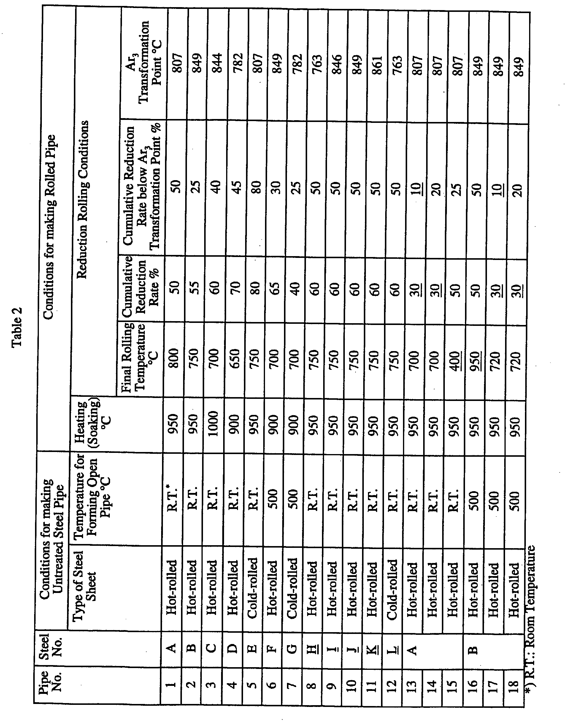
- the heated or soaked steel pipe is subjected to reduction rolling using a series of tandem caliber rolling stands at a cumulative reduction rate of at least about 35%.
- the cumulative reduction rate is the sum of reduction rates for individual caliber rolling stands.
- the upper limit of the cumulative reduction rate is preferably about 95% to prevent local wall thinning and ensure high productivity. More preferably, the cumulative reduction rate is in the range of about 35% to about 90%.
- the cumulative reduction rate at a temperature region below the Ar 3 transformation point is preferably at least about 20%.
- the final rolling temperature is in the range of about 500 to about 900°C. If the final rolling temperature is less than about 500°C or more than about 900°C, the n-value and the r-value contributing to processability are not increased or the limiting bulging ratio LBR at the free bulging test is not increased, thereby resulting in poor hydroformability.
- a series of tandem caliber rolling stands called a reducer, is preferably used.
- the untreated steel pipe having the above-mentioned composition is subjected to the above-mentioned reduction rolling process.
- the rolled steel pipe as a final product has a tensile strength TS of at least about 590 MPa, and a high n ⁇ r product, indicating significantly excellent hydroformability.
- Each of steel sheets (hot-rolled steel sheets and cold-rolled annealed steel sheets) having compositions shown in Table 1 was rolled at room temperature (cold-rolled) or at a warm temperature (500°C to 700°C) to form open pipes. Edges of two open pipes were but-jointed by induction heating to form a welded steel pipe having an outer diameter of 146 mm and a wall thickness of 2.6 mm. Each welded steel pipe as an untreated steel pipe was subjected to reduction rolling under conditions shown in Table 2 to form a rolled steel pipe (final product).
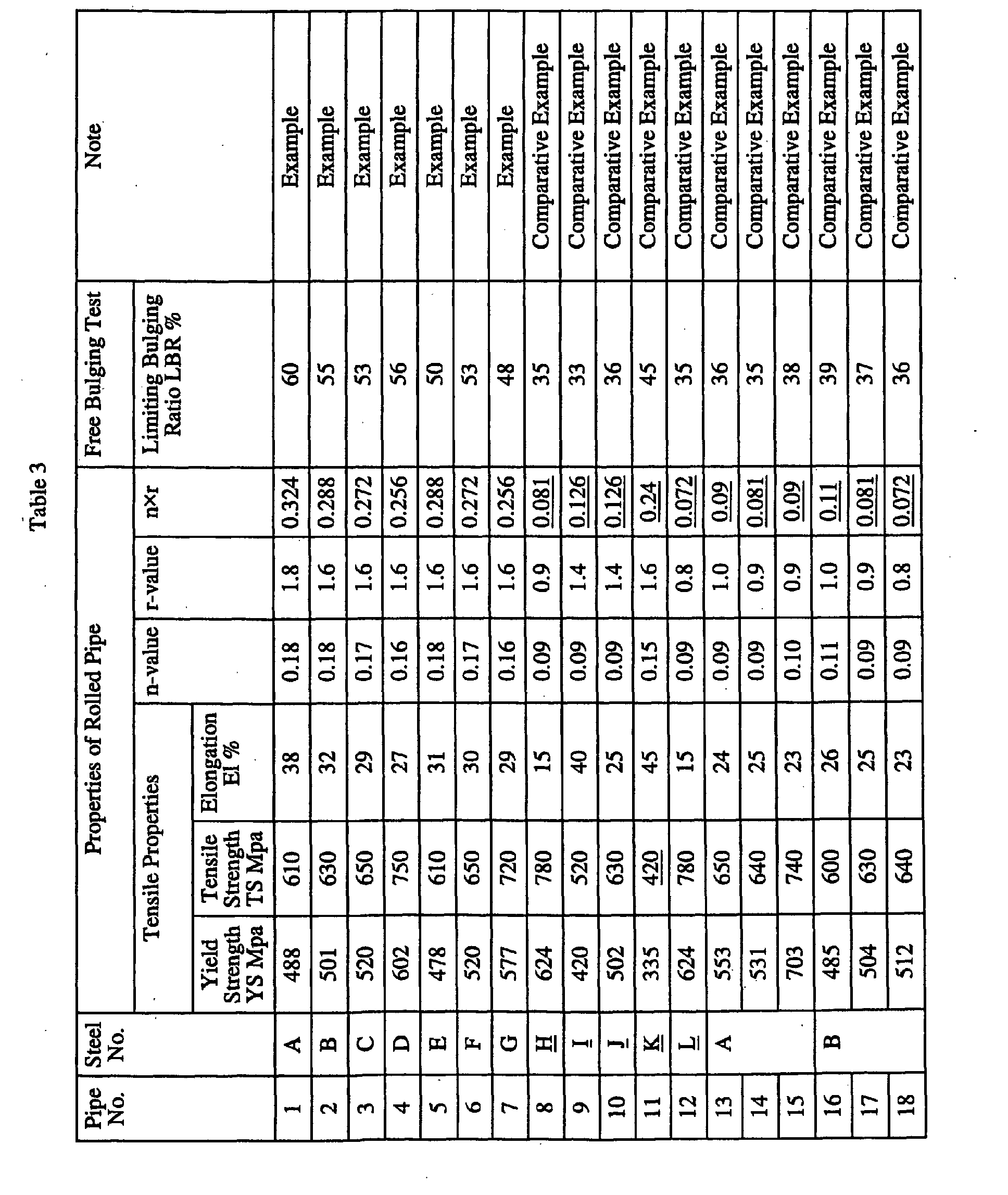
- Tensile test pieces (JIS No. 12A test pieces) in the longitudinal direction were prepared from the rolled steel pipe to measure the tensile properties (yield strength, tensile strength, and elongation), the n-value, and the r-value of the rolled steel pipe.
- n (In ⁇ 10% - ln ⁇ 5% )/( In e 10% - In e 5% )
- r ln(W i /W f )/ln(T i /T f ) wherein W i is the initial width, W f is the final width, T i is the initial thickness, and T f is the final thickness.
- strain gauges were bonded to the tensile test piece, and the true strain was measured in the longitudinal direction and the width direction within a nominal strain in the longitudinal direction of 6% to 7% to determine the r-value and the n-value.
- Each rolled steel pipe as a final product was cut into a length of 500 mm to use as a hydroforming test piece.
- the cut pipe was loaded into the hydroforming apparatus and water was supplied from one end of the pipe to burst the pipe by circular free bulging deformation.
- LBR(%) (d max -d 0 )/d 0 ⁇ 100
- d max is the maximum outer diameter (mm) of the pipe at burst (break)
- d 0 is the outer diameter of the pipe before the test.
- the mold sizes shown in Fig. 1 l c was 127 mm
- d c was 127
- the welded steel pipes according to the invention each have a tensile strength of at least about 590 MPa, a high n-value, a high r-value, and an n ⁇ r product of at least about 0.22, showing excellent processability and hydroformability.
- welded steel pipes according to Comparative Examples each have a low n ⁇ r product and a low LBR, showing poor hydroformability.
- the welded steel pipes according to Comparative Examples are unsuitable for components that require hydroforming.
Landscapes
- Engineering & Computer Science (AREA)
- Mechanical Engineering (AREA)
- Physics & Mathematics (AREA)
- Chemical & Material Sciences (AREA)
- Fluid Mechanics (AREA)
- Organic Chemistry (AREA)
- Materials Engineering (AREA)
- Metallurgy (AREA)
- Crystallography & Structural Chemistry (AREA)
- Thermal Sciences (AREA)
- Manufacturing & Machinery (AREA)
- Heat Treatment Of Steel (AREA)
- Shaping Metal By Deep-Drawing, Or The Like (AREA)
Abstract
Description

Claims (11)
- A welded steel pipe having excellent hydroformability having a composition comprising, on the basis of mass percent:wherein the welded steel pipe has a tensile strength of at least about 590 MPa and an n×r product of an n-value and an r-value is at least about 0.22.about 0.03% to about 0.2% C;about 0.01% to about 2.0% Si;about 1.0% to about 1.5% Mn;about 0.01% to about 0.1% P;about 0.01% or less of S;about 0.01% to about 1.0% Cr;about 0.01% to about 0.1% Al;about 0.01% to about 0.1% Nb;about 0.01% to about 0.1% Ti;about 0.01% to about 0.1% V;about 0.001% to about 0.01% N; andthe balance being Fe and incidental impurities,
- The welded steel pipe according to Claim 1, wherein the n-value is at least about 0.15 or the r-value is at least about 1.5.
- The welded steel pipe according to Claim 1, further comprising at least one group of Group A and Group B,
wherein Group A includes at least one element of about 1.0% or less of Cu, about 1.0% or less of Ni, about 1.0% or less of Mo, and about 0.01% or less of B; and Group B includes at least one element of about 0.02% or less of Ca and about 0.02% or less of a rare earth element. - The welded steel pipe according to Claim 2, further comprising at least one group of Group A and Group B,
wherein Group A includes at least one element of about 1.0% or less of Cu, about 1.0% or less of Ni, about 1.0% or less of Mo, and about 0.01% or less of B; and Group B includes at least one element of about 0.02% or less of Ca and about 0.02% or less of a rare earth element. - The welded steel pipe according to Claim 1, wherein the tensile strength is up to about 780 MPa.
- A method for making a welded steel pipe having excellent hydroformability comprising:heating or soaking an untreated welded steel pipe having a steel composition containing, on the basis of mass percent: about 0.03% to about 0.2% C, about 2.0% or less of Si, about 1.0% to about 1.5% Mn, about 0.1% or less of P, about 0.01% or less of S, about 1.0% or less of Cr, about 0.1% or less of Al, about 0.1% or less of Nb, about 0.1% or less of Ti, about 0.1% or less of V, and about 0.01% or less of N; andreduction-rolling the treated steel pipe at a cumulative reduction rate of at least about 35% and a final rolling temperature of about 500°C to about 900°C, such that the welded steel pipe has a tensile strength of at least about 590 MPa and an n×r product of an n-value and an r-value of at least about 0.22.
- The method for making a welded steel pipe according to Claim 6, wherein the treated steel pipe is reduction-rolled at a cumulative reduction rate of at least about 20% at a temperature below the Ar3 transformation point.
- The method for making a welded steel pipe according to Claim 6, further comprising at least one group of Group A and Group B,
wherein Group A includes at least one element of about 1.0% or less of Cu, about 1.0% or less of Ni, about 1.0% or less of Mo, and about 0.01% or less of B; and Group B includes at least one element of about 0.02% or less of Ca and about 0.02% or less of a rare earth element. - The method for making a welded steel pipe according to Claim 7, further comprising at least one group of Group A and Group B,
wherein Group A includes at least one element of about 1.0% or less of Cu, about 1.0% or less of Ni, about 1.0% or less of Mo, and about 0.01% or less of B; and Group B includes at least one element of about 0.02% or less of Ca and about 0.02% or less of a rare earth element. - The method for making a welded steel pipe according to Claim 6, wherein heating is performed at about 700°C to about 1100°C.
- The method for making a welded steel pipe according to Claim 6, wherein the cumulative reduction rate is up to about 90%.
Applications Claiming Priority (2)
| Application Number | Priority Date | Filing Date | Title |
|---|---|---|---|
| JP2001163864 | 2001-05-31 | ||
| JP2001163864 | 2001-05-31 |
Publications (3)
| Publication Number | Publication Date |
|---|---|
| EP1264645A2 true EP1264645A2 (en) | 2002-12-11 |
| EP1264645A3 EP1264645A3 (en) | 2003-05-07 |
| EP1264645B1 EP1264645B1 (en) | 2005-05-11 |
Family
ID=19006762
Family Applications (1)
| Application Number | Title | Priority Date | Filing Date |
|---|---|---|---|
| EP02012118A Expired - Lifetime EP1264645B1 (en) | 2001-05-31 | 2002-05-31 | Welded steel pipe having excellent hydroformability and method for making the same |
Country Status (6)
| Country | Link |
|---|---|
| US (1) | US6749954B2 (en) |
| EP (1) | EP1264645B1 (en) |
| KR (1) | KR100878731B1 (en) |
| CA (1) | CA2388480C (en) |
| DE (1) | DE60204082T2 (en) |
| ES (1) | ES2242801T3 (en) |
Cited By (2)
| Publication number | Priority date | Publication date | Assignee | Title |
|---|---|---|---|---|
| EP1264902A3 (en) * | 2001-05-31 | 2003-10-15 | Kawasaki Steel Corporation | Welded steel pipe for hydroforming and method for making the same |
| CN102211270A (en) * | 2011-04-06 | 2011-10-12 | 宝鸡鑫泽钛镍有限公司 | Process for manufacturing high-precision titanium and titanium alloy tube |
Families Citing this family (31)
| Publication number | Priority date | Publication date | Assignee | Title |
|---|---|---|---|---|
| US7552776B2 (en) | 1998-12-07 | 2009-06-30 | Enventure Global Technology, Llc | Anchor hangers |
| US7055608B2 (en) * | 1999-03-11 | 2006-06-06 | Shell Oil Company | Forming a wellbore casing while simultaneously drilling a wellbore |
| US7410000B2 (en) | 2001-01-17 | 2008-08-12 | Enventure Global Technology, Llc. | Mono-diameter wellbore casing |
| WO2003042486A2 (en) | 2001-11-12 | 2003-05-22 | Enventure Global Technology | Collapsible expansion cone |
| GB2406126B (en) | 2002-06-10 | 2006-03-15 | Enventure Global Technology | Mono-diameter wellbore casing |
| WO2004027392A1 (en) * | 2002-09-20 | 2004-04-01 | Enventure Global Technology | Pipe formability evaluation for expandable tubulars |
| DE60315172T2 (en) | 2002-09-20 | 2008-04-10 | Enventure Global Technology, Houston | GROUND PACKER FOR FORMING A DRILLING HOOD WITH UNIFORM DIAMETER |
| US7886831B2 (en) | 2003-01-22 | 2011-02-15 | Enventure Global Technology, L.L.C. | Apparatus for radially expanding and plastically deforming a tubular member |
| US7438133B2 (en) | 2003-02-26 | 2008-10-21 | Enventure Global Technology, Llc | Apparatus and method for radially expanding and plastically deforming a tubular member |
| WO2004067961A2 (en) * | 2003-01-27 | 2004-08-12 | Enventure Global Technology | Lubrication system for radially expanding tubular members |
| GB2429480B (en) * | 2003-02-18 | 2007-09-26 | Enventure Global Technology | Protective compression and tension sleeves for threaded connections for radially expandable tubular members |
| GB2415454B (en) | 2003-03-11 | 2007-08-01 | Enventure Global Technology | Apparatus for radially expanding and plastically deforming a tubular member |
| CA2527117A1 (en) * | 2003-05-28 | 2004-12-09 | Sumitomo Metal Industries, Ltd. | A use of a steel pipe for embedding-expanding as an oil well and a method of embedding-expanding of oil well pipes |
| GB2432386B (en) * | 2003-08-14 | 2008-03-05 | Enventure Global Technology | Expandable tubular |
| US7712522B2 (en) | 2003-09-05 | 2010-05-11 | Enventure Global Technology, Llc | Expansion cone and system |
| GB2432384B (en) * | 2003-09-05 | 2008-04-09 | Enventure Global Technology | Expandable tubular |
| EP1792043A4 (en) * | 2004-08-11 | 2010-01-20 | Enventure Global Technology | Expandable tubular member having variable material properties |
| CA2577083A1 (en) | 2004-08-13 | 2006-02-23 | Mark Shuster | Tubular member expansion apparatus |
| JP2008534822A (en) * | 2005-03-21 | 2008-08-28 | エンベンチャー グローバル テクノロジー、エルエルシー | Radial expansion system |
| US8182252B2 (en) * | 2007-10-30 | 2012-05-22 | Moyno, Inc. | Progressing cavity pump with split stator |
| US8215014B2 (en) * | 2007-10-31 | 2012-07-10 | Moyno, Inc. | Method for making a stator |
| JP5399681B2 (en) * | 2008-10-08 | 2014-01-29 | Jfeスチール株式会社 | High workability and high strength steel pipe excellent in chemical conversion and process for producing the same |
| CN101694250B (en) * | 2009-10-13 | 2011-04-06 | 天津钢管集团股份有限公司 | 500MPa-grade VN alloying non-tempering seamless steel tube and manufacturing method thereof |
| CN101942978B (en) * | 2010-08-12 | 2012-01-11 | 中国石油天然气集团公司 | Preparation method of continuous expansion pipe with high strength and high plastic elasticity |
| EP2756191A2 (en) * | 2011-09-12 | 2014-07-23 | Alcoa Inc. | Expandable member and method of making the same |
| US9528327B1 (en) * | 2011-09-23 | 2016-12-27 | Global Tubing Llc | Coiled tubing optimized for long, horizontal completions |
| EP2831628A2 (en) * | 2012-03-30 | 2015-02-04 | Koninklijke Philips N.V. | Portable medical imager with gui interface comprising a motion sensor |
| EP2907598B1 (en) * | 2014-02-18 | 2016-06-15 | C.R.F. Società Consortile per Azioni | Method for manufacturing a camshaft for an internal combustion engine, by expanding a tubular element with a high pressure fluid and simultaneously compressing the tubular element axially |
| WO2020099124A1 (en) * | 2018-11-12 | 2020-05-22 | Aleris Rolled Products Germany Gmbh | Method of producing a high-energy hydroformed structure from a 7xxx-series alloy |
| CN110314973B (en) * | 2019-06-24 | 2021-04-23 | 浙江久立特材科技股份有限公司 | Die for preparing heat exchanger pipe fitting |
| CN110530188B (en) * | 2019-06-24 | 2021-07-23 | 浙江久立特材科技股份有限公司 | Pipe fitting of heat exchanger |
Family Cites Families (9)
| Publication number | Priority date | Publication date | Assignee | Title |
|---|---|---|---|---|
| JPH01296142A (en) * | 1988-05-24 | 1989-11-29 | Kowa Co | Two-dimensional image comparison inspecting device |
| JP3853428B2 (en) * | 1995-08-25 | 2006-12-06 | Jfeスチール株式会社 | Method and equipment for drawing and rolling steel pipes |
| JP3481409B2 (en) * | 1996-12-17 | 2003-12-22 | 新日本製鐵株式会社 | Hydroforming method of steel pipe |
| WO1998049362A1 (en) * | 1997-04-30 | 1998-11-05 | Kawasaki Steel Corporation | Steel material having high ductility and high strength and process for production thereof |
| EP0924312B1 (en) * | 1997-06-26 | 2005-12-07 | JFE Steel Corporation | Method for manufacturing super fine granular steel pipe |
| JP3731103B2 (en) * | 1997-12-15 | 2006-01-05 | Jfeスチール株式会社 | High-strength ERW steel pipe excellent in hydraulic bulge formability and manufacturing method thereof |
| JP3785828B2 (en) * | 1998-09-21 | 2006-06-14 | Jfeスチール株式会社 | Steel pipe drawing method |
| JP3840535B2 (en) * | 1998-10-08 | 2006-11-01 | 新日本製鐵株式会社 | Manufacturing method of high ductility ERW steel pipe |
| JP3794230B2 (en) * | 2000-01-28 | 2006-07-05 | Jfeスチール株式会社 | Manufacturing method of high workability steel pipe |
-
2002
- 2002-05-31 DE DE60204082T patent/DE60204082T2/en not_active Expired - Lifetime
- 2002-05-31 KR KR1020020030564A patent/KR100878731B1/en not_active Expired - Fee Related
- 2002-05-31 CA CA002388480A patent/CA2388480C/en not_active Expired - Fee Related
- 2002-05-31 ES ES02012118T patent/ES2242801T3/en not_active Expired - Lifetime
- 2002-05-31 US US10/161,407 patent/US6749954B2/en not_active Expired - Fee Related
- 2002-05-31 EP EP02012118A patent/EP1264645B1/en not_active Expired - Lifetime
Cited By (4)
| Publication number | Priority date | Publication date | Assignee | Title |
|---|---|---|---|---|
| EP1264902A3 (en) * | 2001-05-31 | 2003-10-15 | Kawasaki Steel Corporation | Welded steel pipe for hydroforming and method for making the same |
| US6723453B2 (en) | 2001-05-31 | 2004-04-20 | Jfe Steel Corporation | Welded steel pipe having excellent hydroformability and method for making the same |
| CN102211270A (en) * | 2011-04-06 | 2011-10-12 | 宝鸡鑫泽钛镍有限公司 | Process for manufacturing high-precision titanium and titanium alloy tube |
| CN102211270B (en) * | 2011-04-06 | 2012-11-07 | 宝鸡鑫泽钛镍有限公司 | Process for manufacturing high-precision titanium and titanium alloy tube |
Also Published As
| Publication number | Publication date |
|---|---|
| KR20020092237A (en) | 2002-12-11 |
| US20030008171A1 (en) | 2003-01-09 |
| DE60204082T2 (en) | 2005-11-17 |
| US6749954B2 (en) | 2004-06-15 |
| EP1264645A3 (en) | 2003-05-07 |
| CA2388480C (en) | 2008-12-23 |
| DE60204082D1 (en) | 2005-06-16 |
| CA2388480A1 (en) | 2002-11-30 |
| EP1264645B1 (en) | 2005-05-11 |
| KR100878731B1 (en) | 2009-01-14 |
| ES2242801T3 (en) | 2005-11-16 |
Similar Documents
| Publication | Publication Date | Title |
|---|---|---|
| EP1264645B1 (en) | Welded steel pipe having excellent hydroformability and method for making the same | |
| EP2007914B1 (en) | Low carbon alloy steel tube having ultra high strength and excellent toughness at low temperature and method of manufacturing the same | |
| EP1264910B1 (en) | Steel pipe having excellent formability and method for production thereof | |
| EP1678335B1 (en) | Low carbon alloy steel tube having ultra high strength and excellent toughness at low temperature and method of manufacturing the same | |
| US20090238714A1 (en) | Seamless Steel Tube for an Airbag Accumulator and Process for its Manufacture | |
| CN100460527C (en) | Low carbon alloy steel pipe having ultra-high strength and excellent toughness at low temperature and method for manufacturing the same | |
| EP2468909B1 (en) | Highly processable steel sheet for three-piece welded can and method for producing same | |
| EP2578705A1 (en) | Process for producing steel pipe for air bag | |
| JP3318467B2 (en) | Manufacturing method of high strength and high toughness steel pipe with excellent workability | |
| EP0758685B1 (en) | Fe-Cr alloy exhibiting excellent ridging resistance and surface characteristics | |
| EP1264902B1 (en) | Welded steel pipe for hydroforming and method for making the same | |
| EP1394276B1 (en) | High tensile hot-rolled steel sheet excellent in resistance to scuff on mold and in fatigue characteristics | |
| JP2003201543A (en) | Steel pipe excellent in workability and method for producing the same | |
| US6682829B2 (en) | Welded steel pipe having excellent hydroformability and method for making the same | |
| JP3965563B2 (en) | Welded steel pipe excellent in hydroforming property and manufacturing method thereof | |
| JP2005060796A (en) | High strength and high toughness welded steel pipe for airbag bottle and method for producing the same | |
| JP4126950B2 (en) | Welded steel pipe excellent in hydroforming property and manufacturing method thereof | |
| JP4126949B2 (en) | Welded steel pipe excellent in hydroforming property and manufacturing method thereof | |
| JP4244749B2 (en) | Welded steel pipe excellent in hydroforming property and burring property and manufacturing method thereof | |
| JP3821073B2 (en) | Hot-rolled material for hydroform forming steel pipe and method for producing the same |
Legal Events
| Date | Code | Title | Description |
|---|---|---|---|
| PUAI | Public reference made under article 153(3) epc to a published international application that has entered the european phase |
Free format text: ORIGINAL CODE: 0009012 |
|
| AK | Designated contracting states |
Kind code of ref document: A2 Designated state(s): AT BE CH CY DE DK ES FI FR GB GR IE IT LI LU MC NL PT SE TR |
|
| AX | Request for extension of the european patent |
Free format text: AL;LT;LV;MK;RO;SI |
|
| PUAL | Search report despatched |
Free format text: ORIGINAL CODE: 0009013 |
|
| AK | Designated contracting states |
Designated state(s): AT BE CH CY DE DK ES FI FR GB GR IE IT LI LU MC NL PT SE TR |
|
| AX | Request for extension of the european patent |
Extension state: AL LT LV MK RO SI |
|
| 17P | Request for examination filed |
Effective date: 20030424 |
|
| RAP1 | Party data changed (applicant data changed or rights of an application transferred) |
Owner name: JFE STEEL CORPORATION |
|
| 17Q | First examination report despatched |
Effective date: 20031212 |
|
| AKX | Designation fees paid |
Designated state(s): DE ES FR GB IT SE |
|
| GRAP | Despatch of communication of intention to grant a patent |
Free format text: ORIGINAL CODE: EPIDOSNIGR1 |
|
| GRAS | Grant fee paid |
Free format text: ORIGINAL CODE: EPIDOSNIGR3 |
|
| GRAA | (expected) grant |
Free format text: ORIGINAL CODE: 0009210 |
|
| AK | Designated contracting states |
Kind code of ref document: B1 Designated state(s): DE ES FR GB IT SE |
|
| REG | Reference to a national code |
Ref country code: GB Ref legal event code: FG4D |
|
| REG | Reference to a national code |
Ref country code: IE Ref legal event code: FG4D |
|
| REF | Corresponds to: |
Ref document number: 60204082 Country of ref document: DE Date of ref document: 20050616 Kind code of ref document: P |
|
| REG | Reference to a national code |
Ref country code: SE Ref legal event code: TRGR |
|
| REG | Reference to a national code |
Ref country code: ES Ref legal event code: FG2A Ref document number: 2242801 Country of ref document: ES Kind code of ref document: T3 |
|
| PLBE | No opposition filed within time limit |
Free format text: ORIGINAL CODE: 0009261 |
|
| STAA | Information on the status of an ep patent application or granted ep patent |
Free format text: STATUS: NO OPPOSITION FILED WITHIN TIME LIMIT |
|
| ET | Fr: translation filed | ||
| 26N | No opposition filed |
Effective date: 20060214 |
|
| PGFP | Annual fee paid to national office [announced via postgrant information from national office to epo] |
Ref country code: ES Payment date: 20080529 Year of fee payment: 7 |
|
| PGFP | Annual fee paid to national office [announced via postgrant information from national office to epo] |
Ref country code: SE Payment date: 20080509 Year of fee payment: 7 |
|
| REG | Reference to a national code |
Ref country code: ES Ref legal event code: FD2A Effective date: 20090601 |
|
| PG25 | Lapsed in a contracting state [announced via postgrant information from national office to epo] |
Ref country code: ES Free format text: LAPSE BECAUSE OF NON-PAYMENT OF DUE FEES Effective date: 20090601 |
|
| PG25 | Lapsed in a contracting state [announced via postgrant information from national office to epo] |
Ref country code: SE Free format text: LAPSE BECAUSE OF NON-PAYMENT OF DUE FEES Effective date: 20090601 |
|
| PGFP | Annual fee paid to national office [announced via postgrant information from national office to epo] |
Ref country code: GB Payment date: 20140528 Year of fee payment: 13 |
|
| PGFP | Annual fee paid to national office [announced via postgrant information from national office to epo] |
Ref country code: FR Payment date: 20140509 Year of fee payment: 13 Ref country code: DE Payment date: 20140528 Year of fee payment: 13 Ref country code: IT Payment date: 20140521 Year of fee payment: 13 |
|
| REG | Reference to a national code |
Ref country code: DE Ref legal event code: R119 Ref document number: 60204082 Country of ref document: DE |
|
| GBPC | Gb: european patent ceased through non-payment of renewal fee |
Effective date: 20150531 |
|
| PG25 | Lapsed in a contracting state [announced via postgrant information from national office to epo] |
Ref country code: IT Free format text: LAPSE BECAUSE OF NON-PAYMENT OF DUE FEES Effective date: 20150531 |
|
| REG | Reference to a national code |
Ref country code: FR Ref legal event code: ST Effective date: 20160129 |
|
| PG25 | Lapsed in a contracting state [announced via postgrant information from national office to epo] |
Ref country code: DE Free format text: LAPSE BECAUSE OF NON-PAYMENT OF DUE FEES Effective date: 20151201 Ref country code: GB Free format text: LAPSE BECAUSE OF NON-PAYMENT OF DUE FEES Effective date: 20150531 |
|
| PG25 | Lapsed in a contracting state [announced via postgrant information from national office to epo] |
Ref country code: FR Free format text: LAPSE BECAUSE OF NON-PAYMENT OF DUE FEES Effective date: 20150601 |