EP1262760A1 - Verfahren zum Bestimmen der Viskosität einer Betriebsflüssigkeit einer Brennkraftmaschine - Google Patents
Verfahren zum Bestimmen der Viskosität einer Betriebsflüssigkeit einer Brennkraftmaschine Download PDFInfo
- Publication number
- EP1262760A1 EP1262760A1 EP02010021A EP02010021A EP1262760A1 EP 1262760 A1 EP1262760 A1 EP 1262760A1 EP 02010021 A EP02010021 A EP 02010021A EP 02010021 A EP02010021 A EP 02010021A EP 1262760 A1 EP1262760 A1 EP 1262760A1
- Authority
- EP
- European Patent Office
- Prior art keywords
- signal
- viscosity
- values
- oil
- determining
- Prior art date
- Legal status (The legal status is an assumption and is not a legal conclusion. Google has not performed a legal analysis and makes no representation as to the accuracy of the status listed.)
- Granted
Links
Images


Classifications
-
- F—MECHANICAL ENGINEERING; LIGHTING; HEATING; WEAPONS; BLASTING
- F01—MACHINES OR ENGINES IN GENERAL; ENGINE PLANTS IN GENERAL; STEAM ENGINES
- F01M—LUBRICATING OF MACHINES OR ENGINES IN GENERAL; LUBRICATING INTERNAL COMBUSTION ENGINES; CRANKCASE VENTILATING
- F01M11/00—Component parts, details or accessories, not provided for in, or of interest apart from, groups F01M1/00 - F01M9/00
- F01M11/10—Indicating devices; Other safety devices
-
- G—PHYSICS
- G01—MEASURING; TESTING
- G01N—INVESTIGATING OR ANALYSING MATERIALS BY DETERMINING THEIR CHEMICAL OR PHYSICAL PROPERTIES
- G01N11/00—Investigating flow properties of materials, e.g. viscosity, plasticity; Analysing materials by determining flow properties
- G01N11/02—Investigating flow properties of materials, e.g. viscosity, plasticity; Analysing materials by determining flow properties by measuring flow of the material
- G01N11/04—Investigating flow properties of materials, e.g. viscosity, plasticity; Analysing materials by determining flow properties by measuring flow of the material through a restricted passage, e.g. tube, aperture
- G01N11/06—Investigating flow properties of materials, e.g. viscosity, plasticity; Analysing materials by determining flow properties by measuring flow of the material through a restricted passage, e.g. tube, aperture by timing the outflow of a known quantity
-
- F—MECHANICAL ENGINEERING; LIGHTING; HEATING; WEAPONS; BLASTING
- F01—MACHINES OR ENGINES IN GENERAL; ENGINE PLANTS IN GENERAL; STEAM ENGINES
- F01M—LUBRICATING OF MACHINES OR ENGINES IN GENERAL; LUBRICATING INTERNAL COMBUSTION ENGINES; CRANKCASE VENTILATING
- F01M11/00—Component parts, details or accessories, not provided for in, or of interest apart from, groups F01M1/00 - F01M9/00
- F01M11/10—Indicating devices; Other safety devices
- F01M2011/14—Indicating devices; Other safety devices for indicating the necessity to change the oil
- F01M2011/148—Indicating devices; Other safety devices for indicating the necessity to change the oil by considering viscosity
-
- F—MECHANICAL ENGINEERING; LIGHTING; HEATING; WEAPONS; BLASTING
- F16—ENGINEERING ELEMENTS AND UNITS; GENERAL MEASURES FOR PRODUCING AND MAINTAINING EFFECTIVE FUNCTIONING OF MACHINES OR INSTALLATIONS; THERMAL INSULATION IN GENERAL
- F16N—LUBRICATING
- F16N2200/00—Condition of lubricant
- F16N2200/12—Viscosity
-
- G—PHYSICS
- G01—MEASURING; TESTING
- G01N—INVESTIGATING OR ANALYSING MATERIALS BY DETERMINING THEIR CHEMICAL OR PHYSICAL PROPERTIES
- G01N33/00—Investigating or analysing materials by specific methods not covered by groups G01N1/00 - G01N31/00
- G01N33/26—Oils; Viscous liquids; Paints; Inks
- G01N33/28—Oils, i.e. hydrocarbon liquids
- G01N33/30—Oils, i.e. hydrocarbon liquids for lubricating properties
Definitions
- the invention relates to a method for determining the viscosity of a Operating fluid of an internal combustion engine according to the preamble of the claim 1.
- the object of the invention is to provide a method for determining the viscosity of a Operating fluid of an internal combustion engine by measuring the Fill level to indicate that an accurate result with a few measurements delivers and that runs during operation of the internal combustion engine.
- Internal combustion engine of a vehicle is first a first signal that the corresponds over time to the level, and detects a second signal that corresponds to the course over time of a state of the vehicle, which influences the measured level of the operating fluid.
- the first and the second The signal is then passed to a filtering system which evaluates the Signals allowed with regard to their dynamics.
- a third and a fourth signal generated, the third signal result of the filtering of the first and the fourth signal is the result of filtering the second.
- the fourth Signal compared with a threshold and depending on the result of the Comparison formed a ratio of the fourth signal to the third signal.
- the Average over a plurality of values of the ratio of the fourth signal to the third signal corresponds to the viscosity of the operating fluid.
- the advantage of the invention is that sensor signals that are already available in the Combined series of tried and tested sensor arrangements and to determine the viscosity from this as an additional parameter. The necessary for this Computing power is taken over by standard control units.
- the second signal Lateral acceleration of the vehicle is detected.
- the continuous measurement signal of the Oil level sensor is with the continuous signal of the Cross acceleration sensor linked. The result leads to a statement the viscosity of the oil. Lateral accelerations are used for other systems such as ESP recorded regularly.
- the measurement values of the first and second signals are preferably acquired at a rate of approximately 1 to 1.5 / s. This measurement rate is sufficiently large to make reliable statements about viscosity and small enough not to generate large amounts of data.
- a sliding signal is preferably used to filter the first or second signal Standard deviation formed over a first number of values.
- the third or fourth signal form the output of the filtering.
- the sliding standard deviation provides a good statement about the data with relatively simple statistical methods Dynamics of the signals.
- the number of values for determining the sliding standard deviation lies here in the range from 5 to 100. A value of 15 has been found in a series of measurements turned out to be particularly advantageous.
- Forming the average of the ratio of the fourth signal to the third signal advantageously takes place over approximately 50 to 300 values.
- a particularly advantageous embodiment of the method relates to the determination of the Viscosity of an engine of a motor vehicle.
- the QLT oil level sensor from Temic which is already in series production, delivers continuous level signal.
- the information about the present lateral acceleration provides Lateral acceleration sensor of the ESP or chassis control system.
- the level signal changes to Dependence of the driving state, especially in the case of lateral accelerations the centrifugal force has a different instantaneous level on both Sides of the oil pan.
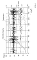
- FIG. 1 shows a diagram with the oil temperature over time, Lateral acceleration and level of a test drive.
- filtering is very general To understand signal conditioning, which is an assessment of the dynamics allowed.
- the filtered signals are related to each other, as soon as the value for the signal, its size for the change in level is responsible - here the lateral acceleration - over one predetermined threshold value K lies.
- the mean over a variety of these Ratio values correspond essentially to the viscosity of the engine oil.
- FIG. 3 shows a flow chart of the method.
- the oil level H and the lateral acceleration Q are measured. It has proven to be sufficient if the signals are scanned or the measured values are recorded at a rate of approximately 1 to 1.5 / s.
- the viscosity can also be calculated by an appropriate arrangement directly in the oil level sensor if there is also data from the Accelerometer can be accessed. Usually the data recorded and evaluated in a central control unit. The calculated viscosity is finally sent to a diagnostic device via an interface or by evaluated an onboard diagnostic device in the motor vehicle.
- the longitudinal acceleration or the engine speed instead of Lateral acceleration can be used as an output variable.
- the longitudinal acceleration or the engine speed can be used as an output variable.
- the longitudinal acceleration or the engine speed can be used as an output variable.
- the longitudinal acceleration is analogous to the lateral acceleration Movement of the oil in the oil pan affects the measured level.
- the use of the signal for the speed as an output variable can be a factor be used so that the amount of oil in the oil circuit is dependent of the speed changes. Only the signal acquisition and the measurement and Filter parameters can be adjusted accordingly to get out of these sizes To be able to determine the viscosity of the oil in an analogous manner.
Landscapes
- Engineering & Computer Science (AREA)
- Mechanical Engineering (AREA)
- General Engineering & Computer Science (AREA)
- Physics & Mathematics (AREA)
- Health & Medical Sciences (AREA)
- Life Sciences & Earth Sciences (AREA)
- Chemical & Material Sciences (AREA)
- Analytical Chemistry (AREA)
- Biochemistry (AREA)
- General Health & Medical Sciences (AREA)
- General Physics & Mathematics (AREA)
- Immunology (AREA)
- Pathology (AREA)
- Lubrication Details And Ventilation Of Internal Combustion Engines (AREA)
- Measurement Of Levels Of Liquids Or Fluent Solid Materials (AREA)
Abstract
Description
- Figur 1
- zeigt ein Diagramm mit dem zeitlichen Verlauf von Öltemperatur, Querbeschleunigung und Füllstandshöhe einer Testfahrt.
- Figur 2
- zeigt ein Diagramm mit dem zeitlichen Verlauf von Öltemperatur, SNV(Q), SNV(H) und ermittelter Viskosität X der Testfahrt.
- Figur 3
- zeigt ein Ablaufdiagramm des Verfahrens.
Claims (6)
- Verfahren zum Bestimmen der Viskosität einer Betriebsflüssigkeit einer Brennkraftmaschine eines Fahrzeugs durch Ermitteln der Füllstandshöhe der Betriebsflüssigkeit, wobei ein erstes Signal erfasst wird, das dem zeitlichen Verlauf der Füllstandshöhe entspricht,
dadurch gekennzeichnet,dass ein zweites Signal erfasst wird, das dem zeitlichen Verlauf eines Zustands des Fahrzeugs entspricht, das Einfluss auf die gemessene Füllstandshöhe der Betriebsflüssigkeit hat,dass das erste und das zweite Signal einer Filterung zugeführt werden, die eine Bewertung der Signale hinsichtlich ihrer Dynamik erlaubt und als Ergebnis ein drittes und ein viertes Signal liefert,dass das vierte Signal mit einem Schwellwert verglichen und in Abhängigkeit vom Ergebnis des Vergleichs ein Verhältnis des vierten Signals zum dritten Signal gebildet wird unddass der Mittelwert über eine Vielzahl von Werten der Viskosität der Betriebsflüssigkeit entspricht. - Verfahren nach Anspruch 1, dadurch gekennzeichnet, dass als zweites Signal die Querbeschleunigung des Fahrzeugs erfasst wird.
- Verfahren nach Anspruch 1 oder 2, dadurch gekennzeichnet, dass die Erfassung der Messwerte des ersten und zweiten Signals mit einer Rate von ca. 1 bis 1,5/s erfolgt.
- Verfahren nach einem der Ansprüche 1 bis 3, dadurch gekennzeichnet, dass zur Filterung eine gleitende Standardabweichung über eine erste Anzahl von Werten des ersten bzw. zweiten Signals gebildet und als drittes bzw. viertes Signal den Ausgang des Filters bilden.
- Verfahren nach Anspruch 4, dadurch gekennzeichnet, dass die Anzahl der Werte zur Ermittlung der gleitenden Standardabweichung im Bereich von 5 bis 100 liegt.
- Verfahren nach einem der Ansprüche 1 bis 5, dadurch gekennzeichnet, dass Mittelwert des Verhältnisses des vierten Signals zum dritten Signal über ca. 50 bis 300 Werte gebildet wird.
Applications Claiming Priority (2)
| Application Number | Priority Date | Filing Date | Title |
|---|---|---|---|
| DE10124888 | 2001-05-22 | ||
| DE10124888A DE10124888C2 (de) | 2001-05-22 | 2001-05-22 | Verfahren zum Bestimmen der Viskosität einer Betriebsflüssigkeit einer Brennkraftmaschine |
Publications (2)
| Publication Number | Publication Date |
|---|---|
| EP1262760A1 true EP1262760A1 (de) | 2002-12-04 |
| EP1262760B1 EP1262760B1 (de) | 2006-12-13 |
Family
ID=7685703
Family Applications (1)
| Application Number | Title | Priority Date | Filing Date |
|---|---|---|---|
| EP02010021A Expired - Lifetime EP1262760B1 (de) | 2001-05-22 | 2002-05-04 | Verfahren zum Bestimmen der Viskosität einer Betriebsflüssigkeit einer Brennkraftmaschine |
Country Status (4)
| Country | Link |
|---|---|
| US (1) | US6658359B2 (de) |
| EP (1) | EP1262760B1 (de) |
| DE (2) | DE10124888C2 (de) |
| ES (1) | ES2275770T3 (de) |
Cited By (1)
| Publication number | Priority date | Publication date | Assignee | Title |
|---|---|---|---|---|
| EP1580550A3 (de) * | 2004-03-26 | 2007-08-01 | Siemens Aktiengesellschaft | Verfahren zum Ermitteln einer für die Viskosität eines Brennkraftmaschinenöls charakteristischen Grösse |
Families Citing this family (8)
| Publication number | Priority date | Publication date | Assignee | Title |
|---|---|---|---|---|
| US9158855B2 (en) * | 2005-06-16 | 2015-10-13 | Buzzmetrics, Ltd | Extracting structured data from weblogs |
| IL213505A0 (en) * | 2011-06-13 | 2011-07-31 | Aharon Krishevsky | A vehicular engine appliance and method for watching thereover |
| US10598650B2 (en) * | 2012-08-22 | 2020-03-24 | General Electric Company | System and method for measuring an operative condition of a machine |
| US9523320B2 (en) * | 2013-10-15 | 2016-12-20 | Ford Global Technologies, Llc | Viscosity detection using sump |
| US10559138B2 (en) | 2015-12-18 | 2020-02-11 | Ge Global Sourcing Llc | Sensor signal processing system and method |
| CN107764364B (zh) * | 2017-09-30 | 2019-12-10 | 惠州华阳通用电子有限公司 | 一种汽车燃油表指示方法及其验证装置与方法 |
| US10681073B2 (en) | 2018-01-02 | 2020-06-09 | International Business Machines Corporation | Detecting unauthorized user actions |
| US10760460B1 (en) * | 2019-06-12 | 2020-09-01 | Ford Global Technologies, Llc | Method and system for engine oil level sensing |
Citations (4)
| Publication number | Priority date | Publication date | Assignee | Title |
|---|---|---|---|---|
| GB1529051A (en) * | 1976-01-15 | 1978-10-18 | Elf Aquitaine | Method of measuring and recording rheological characteristics of a petroleum product |
| DE4011448A1 (de) * | 1990-04-09 | 1991-10-10 | Siemens Ag | Anordnung zur viskositaetsmessung von fluessigkeiten |
| DE19518776A1 (de) * | 1995-05-22 | 1996-11-28 | Bayerische Motoren Werke Ag | Verfahren zum Ermitteln der Viskosität einer Betriebsflüssigkeit eines Kraftfahrzeug-Antriebsaggregats |
| JPH10260126A (ja) * | 1997-03-19 | 1998-09-29 | Koyo Seiko Co Ltd | 流体粘度測定方法ならびに流体粘度測定装置 |
Family Cites Families (8)
| Publication number | Priority date | Publication date | Assignee | Title |
|---|---|---|---|---|
| US4007629A (en) * | 1975-11-04 | 1977-02-15 | Hochstein Peter A | Method and apparatus for monitoring oil degradation |
| US4277971A (en) * | 1980-01-10 | 1981-07-14 | The United States Of America As Represented By The Secretary Of The Army | Fluidic oil viscometer |
| US4733556A (en) * | 1986-12-22 | 1988-03-29 | Ford Motor Company | Method and apparatus for sensing the condition of lubricating oil in an internal combustion engine |
| DE4119437A1 (de) * | 1991-06-13 | 1992-12-17 | Gistl Egmont | Einrichtung zur pegelmessung bei fluessigkeiten, insbesondere fuer oelstaende in kfz-motoren |
| DE4131969C2 (de) * | 1991-09-25 | 1995-08-17 | Fraunhofer Ges Forschung | Schmierölüberwachungseinrichtung |
| US5369396A (en) * | 1992-05-14 | 1994-11-29 | Toyota Jidosha Kabushiki Kaisha | Apparatus for detecting a level of liquid |
| US5377531A (en) * | 1993-09-30 | 1995-01-03 | Gomm; Nelson R. | Portable oil change analyzer |
| US6463796B1 (en) * | 2000-10-12 | 2002-10-15 | The Lubrizol Corporation | Continuous on-board diagnostic lubricant monitoring system and method |
-
2001
- 2001-05-22 DE DE10124888A patent/DE10124888C2/de not_active Expired - Fee Related
-
2002
- 2002-05-04 EP EP02010021A patent/EP1262760B1/de not_active Expired - Lifetime
- 2002-05-04 ES ES02010021T patent/ES2275770T3/es not_active Expired - Lifetime
- 2002-05-04 DE DE50208926T patent/DE50208926D1/de not_active Expired - Lifetime
- 2002-05-15 US US10/146,765 patent/US6658359B2/en not_active Expired - Lifetime
Patent Citations (4)
| Publication number | Priority date | Publication date | Assignee | Title |
|---|---|---|---|---|
| GB1529051A (en) * | 1976-01-15 | 1978-10-18 | Elf Aquitaine | Method of measuring and recording rheological characteristics of a petroleum product |
| DE4011448A1 (de) * | 1990-04-09 | 1991-10-10 | Siemens Ag | Anordnung zur viskositaetsmessung von fluessigkeiten |
| DE19518776A1 (de) * | 1995-05-22 | 1996-11-28 | Bayerische Motoren Werke Ag | Verfahren zum Ermitteln der Viskosität einer Betriebsflüssigkeit eines Kraftfahrzeug-Antriebsaggregats |
| JPH10260126A (ja) * | 1997-03-19 | 1998-09-29 | Koyo Seiko Co Ltd | 流体粘度測定方法ならびに流体粘度測定装置 |
Non-Patent Citations (1)
| Title |
|---|
| PATENT ABSTRACTS OF JAPAN vol. 1998, no. 14 31 December 1998 (1998-12-31) * |
Cited By (1)
| Publication number | Priority date | Publication date | Assignee | Title |
|---|---|---|---|---|
| EP1580550A3 (de) * | 2004-03-26 | 2007-08-01 | Siemens Aktiengesellschaft | Verfahren zum Ermitteln einer für die Viskosität eines Brennkraftmaschinenöls charakteristischen Grösse |
Also Published As
| Publication number | Publication date |
|---|---|
| DE10124888C2 (de) | 2003-04-17 |
| DE50208926D1 (de) | 2007-01-25 |
| ES2275770T3 (es) | 2007-06-16 |
| DE10124888A1 (de) | 2002-12-12 |
| EP1262760B1 (de) | 2006-12-13 |
| US6658359B2 (en) | 2003-12-02 |
| US20020174712A1 (en) | 2002-11-28 |
Similar Documents
| Publication | Publication Date | Title |
|---|---|---|
| AT505105B1 (de) | Verfahren zur beurteilung der fahrbarkeit von fahrzeugen | |
| AT520320B1 (de) | Verfahren und eine Vorrichtung zum Erzeugen eines dynamischen Geschwindigkeitsprofils eines Kraftfahrzeugs | |
| DE3878020T2 (de) | Verfahren und geraet zur ermittlung der mittelstellung des lenkungssystems eines fahrzeugs. | |
| DE102013114913B4 (de) | Verfahren zum Schaltsteuern eines Automatikgetriebes in einem Fahrzeug | |
| DE4015415B4 (de) | Vorrichtung zur Erfassung eines veränderlichen Betriebsparameters | |
| DE2941977A1 (de) | Einrichtung zum optimieren von betriebskenngroessen einer brennkraftmaschine | |
| DE102010039949A1 (de) | Verfahren zur Erkennung fehlender Fahreraktivität am Lenkrad eines Kraftfahrzeugs | |
| DE102012003020A1 (de) | Regelsystem zur Drehzahlregelung eines Antriebsmotors | |
| DE102012217772A1 (de) | Verfahren zur Bestimmung des maximalen Kraftschlussbeiwerts | |
| EP1262760B1 (de) | Verfahren zum Bestimmen der Viskosität einer Betriebsflüssigkeit einer Brennkraftmaschine | |
| DE69126263T2 (de) | Antriebseinheit | |
| DE60218829T2 (de) | Fahrbarkeit-einstufungsmethode und system | |
| DE4215938C2 (de) | Aussetzererkennungssystem bei einem Verbrennungsmotor | |
| DE102005060219A1 (de) | Verfahren und Vorrichtung zur Abschätzung des Reibkoeffizienten zwischen Straße und Reifen eines Kraftfahrzeuges | |
| DE102017122934A1 (de) | Verfahren zur Kontrolle eines Abgasverhaltens einer Verbrennungskraftmaschine | |
| EP1063498A2 (de) | Verfahren und Vorrichtung zur Bestimmung der Flüssigkeitsmenge in einem bewegten Behalter | |
| DE4401835B4 (de) | Vorrichtung zur Ermittlung des Ölwechselzeitpunktes eines Kraftfahrzeugmotors | |
| EP1470978A1 (de) | Verfahren und Vorrichtung zur Erkenung eines Fahrzustands | |
| DE4115647B4 (de) | Steuersystem in einem Fahrzeug | |
| WO2002065065A1 (de) | Verfahren zur ermittlung der füllmenge eines betriebsmittels in einen kraftfahrzeug | |
| DE102011057188A1 (de) | Verfahren und System zum Messen einer Motorölverschlechterung | |
| DE102021112465B4 (de) | Verfahren zum erkennen einer abnormen stelle einer fahrzeuginternen komponente, system zum erkennen der abnormen stelle einer fahrzeuginternen komponente, vorrichtung zum erkennen der abnormen stelle einer fahrzeuginternen komponente, vorrichtung zum steuern einer meldung über eine abnorme stelle einer fahrzeuginternen komponente und vorrichtung zum steuern eines fahrzeugs | |
| DE102006059071A1 (de) | Verfahren zur Bestimmung der Ölqualität | |
| EP2977648A2 (de) | Verfahren und vorrichtung zur erkennung eines übersetzungsverhältnisses an einem fahrzeug | |
| DE10124890C2 (de) | Verfahren zum Bestimmen der Viskosität einer Betriebsflüssigkeit einer Brennkraftmaschine |
Legal Events
| Date | Code | Title | Description |
|---|---|---|---|
| PUAI | Public reference made under article 153(3) epc to a published international application that has entered the european phase |
Free format text: ORIGINAL CODE: 0009012 |
|
| AK | Designated contracting states |
Kind code of ref document: A1 Designated state(s): AT BE CH CY DE DK ES FI FR GB GR IE IT LI LU MC NL PT SE TR |
|
| AX | Request for extension of the european patent |
Free format text: AL;LT;LV;MK;RO;SI |
|
| 17P | Request for examination filed |
Effective date: 20021030 |
|
| AKX | Designation fees paid |
Designated state(s): DE ES FR GB IT SE |
|
| GRAP | Despatch of communication of intention to grant a patent |
Free format text: ORIGINAL CODE: EPIDOSNIGR1 |
|
| GRAS | Grant fee paid |
Free format text: ORIGINAL CODE: EPIDOSNIGR3 |
|
| GRAA | (expected) grant |
Free format text: ORIGINAL CODE: 0009210 |
|
| AK | Designated contracting states |
Kind code of ref document: B1 Designated state(s): DE ES FR GB IT SE |
|
| PG25 | Lapsed in a contracting state [announced via postgrant information from national office to epo] |
Ref country code: IT Free format text: LAPSE BECAUSE OF FAILURE TO SUBMIT A TRANSLATION OF THE DESCRIPTION OR TO PAY THE FEE WITHIN THE PRESCRIBED TIME-LIMIT;WARNING: LAPSES OF ITALIAN PATENTS WITH EFFECTIVE DATE BEFORE 2007 MAY HAVE OCCURRED AT ANY TIME BEFORE 2007. THE CORRECT EFFECTIVE DATE MAY BE DIFFERENT FROM THE ONE RECORDED. Effective date: 20061213 |
|
| REG | Reference to a national code |
Ref country code: GB Ref legal event code: FG4D Free format text: NOT ENGLISH |
|
| REF | Corresponds to: |
Ref document number: 50208926 Country of ref document: DE Date of ref document: 20070125 Kind code of ref document: P |
|
| GBT | Gb: translation of ep patent filed (gb section 77(6)(a)/1977) |
Effective date: 20070124 |
|
| REG | Reference to a national code |
Ref country code: SE Ref legal event code: TRGR |
|
| ET | Fr: translation filed | ||
| REG | Reference to a national code |
Ref country code: ES Ref legal event code: FG2A Ref document number: 2275770 Country of ref document: ES Kind code of ref document: T3 |
|
| PLBE | No opposition filed within time limit |
Free format text: ORIGINAL CODE: 0009261 |
|
| STAA | Information on the status of an ep patent application or granted ep patent |
Free format text: STATUS: NO OPPOSITION FILED WITHIN TIME LIMIT |
|
| 26N | No opposition filed |
Effective date: 20070914 |
|
| PGFP | Annual fee paid to national office [announced via postgrant information from national office to epo] |
Ref country code: ES Payment date: 20080529 Year of fee payment: 7 |
|
| PGFP | Annual fee paid to national office [announced via postgrant information from national office to epo] |
Ref country code: IT Payment date: 20080522 Year of fee payment: 7 |
|
| PGFP | Annual fee paid to national office [announced via postgrant information from national office to epo] |
Ref country code: SE Payment date: 20080513 Year of fee payment: 7 |
|
| PGFP | Annual fee paid to national office [announced via postgrant information from national office to epo] |
Ref country code: GB Payment date: 20080522 Year of fee payment: 7 |
|
| GBPC | Gb: european patent ceased through non-payment of renewal fee |
Effective date: 20090504 |
|
| PG25 | Lapsed in a contracting state [announced via postgrant information from national office to epo] |
Ref country code: GB Free format text: LAPSE BECAUSE OF NON-PAYMENT OF DUE FEES Effective date: 20090504 |
|
| REG | Reference to a national code |
Ref country code: ES Ref legal event code: FD2A Effective date: 20090505 |
|
| PG25 | Lapsed in a contracting state [announced via postgrant information from national office to epo] |
Ref country code: ES Free format text: LAPSE BECAUSE OF NON-PAYMENT OF DUE FEES Effective date: 20090505 |
|
| PG25 | Lapsed in a contracting state [announced via postgrant information from national office to epo] |
Ref country code: IT Free format text: LAPSE BECAUSE OF NON-PAYMENT OF DUE FEES Effective date: 20090504 |
|
| PG25 | Lapsed in a contracting state [announced via postgrant information from national office to epo] |
Ref country code: SE Free format text: LAPSE BECAUSE OF NON-PAYMENT OF DUE FEES Effective date: 20090505 |
|
| PGFP | Annual fee paid to national office [announced via postgrant information from national office to epo] |
Ref country code: DE Payment date: 20140531 Year of fee payment: 13 |
|
| REG | Reference to a national code |
Ref country code: FR Ref legal event code: PLFP Year of fee payment: 14 |
|
| PGFP | Annual fee paid to national office [announced via postgrant information from national office to epo] |
Ref country code: FR Payment date: 20150521 Year of fee payment: 14 |
|
| REG | Reference to a national code |
Ref country code: DE Ref legal event code: R119 Ref document number: 50208926 Country of ref document: DE |
|
| PG25 | Lapsed in a contracting state [announced via postgrant information from national office to epo] |
Ref country code: DE Free format text: LAPSE BECAUSE OF NON-PAYMENT OF DUE FEES Effective date: 20151201 |
|
| REG | Reference to a national code |
Ref country code: FR Ref legal event code: ST Effective date: 20170131 |
|
| PG25 | Lapsed in a contracting state [announced via postgrant information from national office to epo] |
Ref country code: FR Free format text: LAPSE BECAUSE OF NON-PAYMENT OF DUE FEES Effective date: 20160531 |