EP1262654A1 - Electromagnetic fuel injector - Google Patents
Electromagnetic fuel injector Download PDFInfo
- Publication number
- EP1262654A1 EP1262654A1 EP00901896A EP00901896A EP1262654A1 EP 1262654 A1 EP1262654 A1 EP 1262654A1 EP 00901896 A EP00901896 A EP 00901896A EP 00901896 A EP00901896 A EP 00901896A EP 1262654 A1 EP1262654 A1 EP 1262654A1
- Authority
- EP
- European Patent Office
- Prior art keywords
- nozzle body
- fuel
- needle
- swirler
- electromagnetic
- Prior art date
- Legal status (The legal status is an assumption and is not a legal conclusion. Google has not performed a legal analysis and makes no representation as to the accuracy of the status listed.)
- Withdrawn
Links
Images



Classifications
-
- F—MECHANICAL ENGINEERING; LIGHTING; HEATING; WEAPONS; BLASTING
- F02—COMBUSTION ENGINES; HOT-GAS OR COMBUSTION-PRODUCT ENGINE PLANTS
- F02M—SUPPLYING COMBUSTION ENGINES IN GENERAL WITH COMBUSTIBLE MIXTURES OR CONSTITUENTS THEREOF
- F02M61/00—Fuel-injectors not provided for in groups F02M39/00 - F02M57/00 or F02M67/00
- F02M61/16—Details not provided for in, or of interest apart from, the apparatus of groups F02M61/02 - F02M61/14
- F02M61/168—Assembling; Disassembling; Manufacturing; Adjusting
-
- F—MECHANICAL ENGINEERING; LIGHTING; HEATING; WEAPONS; BLASTING
- F02—COMBUSTION ENGINES; HOT-GAS OR COMBUSTION-PRODUCT ENGINE PLANTS
- F02M—SUPPLYING COMBUSTION ENGINES IN GENERAL WITH COMBUSTIBLE MIXTURES OR CONSTITUENTS THEREOF
- F02M51/00—Fuel-injection apparatus characterised by being operated electrically
- F02M51/06—Injectors peculiar thereto with means directly operating the valve needle
- F02M51/061—Injectors peculiar thereto with means directly operating the valve needle using electromagnetic operating means
- F02M51/0625—Injectors peculiar thereto with means directly operating the valve needle using electromagnetic operating means characterised by arrangement of mobile armatures
- F02M51/0664—Injectors peculiar thereto with means directly operating the valve needle using electromagnetic operating means characterised by arrangement of mobile armatures having a cylindrically or partly cylindrically shaped armature, e.g. entering the winding; having a plate-shaped or undulated armature entering the winding
- F02M51/0671—Injectors peculiar thereto with means directly operating the valve needle using electromagnetic operating means characterised by arrangement of mobile armatures having a cylindrically or partly cylindrically shaped armature, e.g. entering the winding; having a plate-shaped or undulated armature entering the winding the armature having an elongated valve body attached thereto
-
- F—MECHANICAL ENGINEERING; LIGHTING; HEATING; WEAPONS; BLASTING
- F02—COMBUSTION ENGINES; HOT-GAS OR COMBUSTION-PRODUCT ENGINE PLANTS
- F02M—SUPPLYING COMBUSTION ENGINES IN GENERAL WITH COMBUSTIBLE MIXTURES OR CONSTITUENTS THEREOF
- F02M61/00—Fuel-injectors not provided for in groups F02M39/00 - F02M57/00 or F02M67/00
- F02M61/04—Fuel-injectors not provided for in groups F02M39/00 - F02M57/00 or F02M67/00 having valves, e.g. having a plurality of valves in series
- F02M61/10—Other injectors with elongated valve bodies, i.e. of needle-valve type
- F02M61/12—Other injectors with elongated valve bodies, i.e. of needle-valve type characterised by the provision of guiding or centring means for valve bodies
-
- F—MECHANICAL ENGINEERING; LIGHTING; HEATING; WEAPONS; BLASTING
- F02—COMBUSTION ENGINES; HOT-GAS OR COMBUSTION-PRODUCT ENGINE PLANTS
- F02M—SUPPLYING COMBUSTION ENGINES IN GENERAL WITH COMBUSTIBLE MIXTURES OR CONSTITUENTS THEREOF
- F02M61/00—Fuel-injectors not provided for in groups F02M39/00 - F02M57/00 or F02M67/00
- F02M61/16—Details not provided for in, or of interest apart from, the apparatus of groups F02M61/02 - F02M61/14
- F02M61/162—Means to impart a whirling motion to fuel upstream or near discharging orifices
-
- F—MECHANICAL ENGINEERING; LIGHTING; HEATING; WEAPONS; BLASTING
- F02—COMBUSTION ENGINES; HOT-GAS OR COMBUSTION-PRODUCT ENGINE PLANTS
- F02M—SUPPLYING COMBUSTION ENGINES IN GENERAL WITH COMBUSTIBLE MIXTURES OR CONSTITUENTS THEREOF
- F02M2200/00—Details of fuel-injection apparatus, not otherwise provided for
- F02M2200/30—Fuel-injection apparatus having mechanical parts, the movement of which is damped
- F02M2200/306—Fuel-injection apparatus having mechanical parts, the movement of which is damped using mechanical means
-
- F—MECHANICAL ENGINEERING; LIGHTING; HEATING; WEAPONS; BLASTING
- F02—COMBUSTION ENGINES; HOT-GAS OR COMBUSTION-PRODUCT ENGINE PLANTS
- F02M—SUPPLYING COMBUSTION ENGINES IN GENERAL WITH COMBUSTIBLE MIXTURES OR CONSTITUENTS THEREOF
- F02M2200/00—Details of fuel-injection apparatus, not otherwise provided for
- F02M2200/80—Fuel injection apparatus manufacture, repair or assembly
- F02M2200/8061—Fuel injection apparatus manufacture, repair or assembly involving press-fit, i.e. interference or friction fit
Definitions
- the present invention relates to an electromagnetic fuel injector (injection valve) for an internal combustion engine.
- This type of fuel injector is configured such that an electromagnetic coil and a yoke are arranged around a hollow cylindrical fixed core. And a nozzle body containing a movable element (thereafter call “needle”) with a valve element is fixed to the lower portion of the yoke, so that the needle is urged toward a valve seat by the force of a return spring.
- needle a movable element
- a two-point support guide system is generally used for the needle in order to achieve the stability of a stroke movement.
- the movable element is a needle valve
- the tip of the needle valve is slidably guided on the inner circumference of a fuel swirler housed inside a nozzle body.
- a large-diameter portion functioning as a guide surface on a movable side is formed in the needle valve, to be thus slidably guided on the inner circumference of the nozzle body.
- a similar two-point support guide system is used for a needle configured by integrally coupling a ball and a rod which serve as a valve element.
- valve element collides with a valve seat during a valve closing operation in the electromagnetic fuel injector, the valve is accidentally opened by a bounce of the valve element, thereby inducing a fear of so-called secondary injection. Therefore, there are various demands for the technique for preventing such secondary injection, the configuration which contributes to assembling facilitation, in particular, automatic assembling, and the like.
- An object of the present invention is to provide a fuel injector which can solve problems such as cost reduction, centering accuracy (coaxial accuracy) and assembling facilitation of a fuel injector, simplicity of component parts, the degree of fixing freedom, and prevention of secondary injection.
- the present invention has been proposed to attain the above-described object by way of a variety of modes.
- the gist of the present invention is as follows:
- An electromagnetic fuel injector is basically configured such that an electromagnetic coil and a yoke are arranged around a fixed core, a nozzle body containing therein a needle with a valve element is fixed to the lower portion of the yoke, and the needle is urged toward a valve seat with application of the force of a return spring, and further, is provided with the following means:
- a hollow fixed core 1 an electromagnetic coil 2 and a yoke 4 are arranged from the center toward the outer diameter in a fuel injector 100, and further, a needle 5 with a valve element is contained inside a nozzle body (also referred to as a nozzle holder) 18 fixed to the lower portion of the yoke 4, wherein the needle 5 is urged toward a valve seat 31 by the force of a return spring 7.
- a nozzle body also referred to as a nozzle holder
- the yoke 4 With respect to the basic movement of the fuel injector 100, when the electromagnetic coil 2 is energized, the yoke 4, the fixed core 1, a movable core 14 (i.e., a part of the needle 5) and the upper portion of the nozzle body 18 constitute a magnetic circuit, so that the needle 5 is attracted against the force of the return spring 7, thereby achieving a valve opening; in contrast, when the energization of the electromagnetic coil 2 is stopped, the needle 5 abuts against the valve seat 31 by the force of the return spring 7, thereby achieving a valve closing.
- the lower end of the fixed core 1 functions as a stopper for receiving the needle 5 during the valve opening.
- the fixed core 1 is formed into an elongated, hollow and slenderly cylindrical shape.
- the fixed core 1 and the nozzle body 18 are coupled to each other via a non-magnetic, cylindrical seal ring 8 extending over the outer circumference of one end on the nozzle body side of the fixed core 1 and the inner circumference of one end of the nozzle body 18.
- the seal ring 8 is ground with material such as SUS316, and is formed into a cylinder having a flange 8a at one end thereof.
- One end of the cylinder on a side opposite to the flange 8a is press-fitted and welded to one end of the outer circumference of the fixed core 1; on the other hand, the flange 8a is press-fitted and welded to an annular step (an annular groove) 18c formed at the inner edge of the upper end of the nozzle body 18.
- Such welding is performed over the entire coupling boundary of, for example, portions designated by reference characters (b) and (c) by laser welding in order to keep sealability.
- annular step 18c is a part having the greatest inner diameter of the stepped inner circumference of the nozzle body 18.
- An upper portion 18b of the nozzle body 18 has greatest inner and outer diameters in the nozzle body 1 in order to house therein the movable core 14a, described later, in such a manner as to allow a freely reciprocating movement (a stroke movement required for opening or closing a valve).
- a slender, long nozzle portion 18a extends from the lower portion.
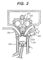
- the long nozzle portion 18a enables an injector body having a large diameter to be placed at a position apart from (i.e., a position without any interference with) a suction valve 101, a drive mechanism 102 for a suction/exhaust valve, a intake manifold 103 or the cylinder head 106 in the case where the suction valve 101, the drive mechanism 102, the intake manifold 103 and the like are mounted at a high density, with an attendant advantage of the higher degree of fixing freedom.
- the upper portion (the large-diameter portion) 18b of the nozzle body 18 extends upward to a position at which a magnetic flux for attracting the movable core is allowed to pass when the electromagnetic coil 2 is energized, that is, to a position at which a part of the magnetic circuit is constituted.
- the upper portion 18b of the nozzle body 18 also serves as a part of the yoke 4.
- the upper end surface of the nozzle body 18 includes the above-described annular step 18c for allowing the flange 8a of the seal ring 8 to be press-fitted thereto while a step 18d to be press-fitted in a spigot joint manner to (i.e., in uneven engagement with) the yoke 4, and therefore, includes three stepped surfaces in total.
- an opening at the lower end i.e., one end facing the nozzle body 18
- a resin mold 3 is formed slightly larger than the outer diameter of the electromagnetic coil 2 with a resin mold 3, and thus, is formed into a so-called drop-bottomed shape.
- a step 4c is formed at the lower end of the yoke to be press-fitted to the step 18d of the nozzle body 18 in the spigot joint manner.
- an upper wall 4b (hereinafter referred to as a shoulder) is formed in such a manner as to cover the upper end of the resin mold 3 of the electromagnetic coil 2.
- a core inserting hole 4a engageable with the outer circumference of the fixed core 1 is formed by drawing.
- the yoke 4 configured as described above is disposed from above the fixed core 1. Furthermore, the yoke 4 is configured such that it can be press-fitted (coupled) to the annular step 18d of the nozzle body 18 in the spigot joint manner in such a manner as to cover the electromagnetic core 2 with the resin mold 3. At a part of the shoulder 4b of the yoke 4 is formed as a window 4d, through which a connector terminal 29 for the electromagnetic coil 3 can be inserted.
- the electromagnetic coil 2 is received at the upper end surface of the nozzle body 18, and then, is pressed at the inner surface of the shoulder 4b of the yoke 4, to be thus fixed thereto.
- the yoke 4 and the nozzle body 18 are annularly welded to each other at a jointed portion (a) of the press-fitted portion (i.e., the spigot-jointed portion) therebetween, and further, the yoke 4 and the fixed core 1 are welded to each other at a position (d), thereby keeping the sealability.
- the fixed core 1, the yoke 4, the needle 5 and the nozzle body 18 are made of, for example, a stainless-based magnetic material (i.e., electromagnetic stainless) in order to constitute the magnetic circuit of the electromagnetic coil 2. Its machining mode will be described later.
- a stainless-based magnetic material i.e., electromagnetic stainless
- the orifice plate 19 is formed by, for example, a stainless-based disk-like chip, and is provided at the center thereof with an injection orifice (an orifice) 20, upstream of which the valve seat 31 is formed.
- the orifice plate 19 is press-fitted to the inner circumference 18f of the lower end of the nozzle body 18.
- the swirler 21 is loosely fitted to the inner circumference of the lower end of the nozzle body 18, and is made of a sintered alloy such as SUS416.
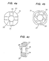
- the swirler 21 is formed by a substantially disk-like chip, and is provided at the center thereof with a center hole (a guide) 25 for slidably guiding the tip (the valve element) of the needle 5 and at the upper surface thereof with a guide groove 24 for guiding fuel toward the outer circumference, as shown in Figs. 4(a) and 4(c).
- annular step (an annular passage) 23 is formed at the peripheral edge of the lower surface of the swirler 21, and further, a plurality of, for example, six passage grooves 26 for forming a fuel swirl are arranged between the annular passage 23 and the center hole 25.
- the passage groove 26 is formed in substantially the tangential direction from the outer diameter of the swirler 21 to the inner diameter thereof, so as to generate swirling force in the fuel injected from the passage groove 26 toward the lower end of the center hole 25.
- the annular step 23 is formed because it need serve as a fuel sump. Moreover, a plurality of chamfers 27 are formed at the outer circumference of the swirler 21. The chamfers 27 are referred to in machining the grooves 24 and 26 and the like.
- the inner circumference (the stepped inner circumference) 18f with a receiving surface 18e for receiving the swirler 21 and the orifice plate 19.
- the swirler 21 is received at the receiving surface 18e of the nozzle body 18, to be loosely fitted to the inner circumference of the nozzle body.
- the orifice plate 19 is press-fitted and welded to the inner circumference in such a manner as to press the swirler 21.
- the swirler 21 and the orifice plate 19 are disposed in the above-described manner, so that the swirler 21 can be held between the receiving surface 18e and the orifice plate 19, and further, an annular fuel passage 22 is defined between the outer circumference of the swirler 21 and the inner circumference of the tip of the nozzle body 18.
- the annular fuel passage 22 can be sufficiently secured as a fuel passage without any chamber 27. Via these annular fuel passages 22 and 23, the fuel can flow into the groove 26 for forming a swirl in the swirler 21.
- the upper surface of the swirler 21 is configured such that the fuel guide groove 24 is formed for the purpose of the press-contact with the receiving surface 18e formed in the nozzle body 18, so that the fuel staying upstream of the swirler can flow into the annular fuel passage 22 around the swirler 21 via the groove 24.
- the groove 24 may be formed on a side of the receiving surface 18e of the nozzle body other than the upper end surface of the swirler 21.
- a passage groove for guiding the fuel around the swirler is defined between the upper end surface of the swirler and the receiving surface of the nozzle body receiving the former.
- a part of the orifice plate 19 intrudes into the groove 26 formed at one end surface of the swirler 21 to such an extent that the part cannot interfere with the flow in the passage groove, and thus, secures the function of a detent of the swirler 21.
- the hardness of the swirler 21 is made to be greater than that of the orifice plate 19, a part of the orifice plate 19 can bite the groove 26 when the orifice plate 19 is press-fitted, thereby securing the detent of the swirler 21 and preventing any misalignment of the swirler 21.
- the needle 5 includes a valve rod (i.e., a needle) 16 and the hollow, cylindrical movable core 14 having an outer-diameter greater than that of the valve rod 16.
- the valve rod 16 and the movable core 14 are constituted of separate members, and are integrally coupled to each other by press-fitting and welding the valve rod 16 to one end of the movable core 14.
- each of the movable core 14 and the valve rod 16 serves as a guide surface on a movable side.
- one part 14a at the outer peripheral surface of the movable core 14 is slidably guided on the inner circumference of the seal ring 8 during a stroke movement at the time of the valve opening or closing, and then, the peripheral surface near the tip of the valve rod 16 is slidably guided to the center hole 25 of the swirler 21, thereby constituting a so-called two-point support guide system.
- the diameter of the outer circumference 14a of the upper portion of the movable core 14 is made to be greater than that of an outer circumference 14b of the lower portion thereof, so that the outer circumference 14a of the upper portion is slidably guided at the inner circumferential surface of the seal ring 8; in the meantime, the diameter of the outer circumference 14b of the lower portion is made to be smaller than that of the outer circumference 14a of the upper portion, so that a sufficient fuel passage 13 can be secured between the outer circumference 14b of the lower portion and the inner circumference of the nozzle body 18.
- a step 14c is formed at the inner surface of the upper portion of the movable core 14, and is provided with an annular plate spring (i.e., a damper plate) 50.
- the plate spring 50 is formed into an annular shape, and an inside portion designated by reference numeral 51 is punched.
- a plurality of elastic pieces 52 projecting inward are formed by punching in arrangement at equal intervals in the circumferential direction.
- the elastic pieces 52 in the plate spring 50 receive one end of a cylindrical movable mass (i.e., a weight) 9, which is, for example, a carbon steel forging product.
- the movable mass 9 is positioned over one end of the inner circumference of the fixed core 1 and one end of the inner circumference of the movable core 14.
- a hollow hole 11 of the fixed core 1 serves as a fuel passage. Inside the hollow hole 11 are contained the movable mass 9, the return spring 7 and a spring presser 6 in order from under.
- a filter 30 is disposed at the upper end of the hollow hole 11.
- the spring presser 6 is fixed by caulking a peripheral portion 10 of the fixed core 1.
- the movable mass 9 is interposed between the return spring 7 and the needle 5 (the movable core 14) in such a manner as to be freely moved in an axial direction independently of the needle 5.
- the spring plate 50 is interposed between the movable mass 9 and the needle 5, so that the elastic pieces 52 of the spring plate 50 receive the movable mass 9.
- the movable mass 9 fulfills a damper function of suppressing a bounce of the needle 5 during a valve closing movement owing to its independence of the needle 5 with a valve.
- This damper function produces a remarkably effective result, the principle of which is considered as follows: namely, it is considered that although the needle 5 is about to bounce when the needle 5 collides against the valve seat 31 by the force of the return spring 7 during the valve closing movement, the inertia of the movable mass 9 and the resilient deformation of the spring plate 50 absorb kinetic energy of the bounce at that time, thereby attenuating the bounce.
- a connector mold (i.e., a resin mold) 27 is formed around a portion projecting from the yoke 4, of the fixed core 1.
- the component parts are inserted from above in reference to the nozzle body 18 except for resin molding with the connector mold.
- the yoke 4 is a pressed and cut product.
- the nozzle body 18 is a cold forged product through not cutting but lathing.
- the swirler 21 is a sintered product through cutting.
- the orifice plate 19 is lathed, and further, is quenched in order to enhance its hardness.
- the valve seat 31 and the orifice 20 are ground and end-lapped.
- valve rod 16 is quenched, and the movable core 14 is annealed. Thereafter, these component parts 14 and 16 are integrally coupled to each other by press-fitting and welding, thus constituting the needle 5.
- the outer circumference of the needle 5 is ground.
- the outer peripheral surface (the movable guide surface) 14a at the upper portion and the end surface (the movable stopper surface) in the movable core 14 are subjected to hard plating.
- the fixed core 1 is a cold forged product through lathing and annealing, and further, the tip thereof serving as a stopper surface with respect to the needle is subjected to hard plating.
- the seal ring 8 is lathed, and then, is press-fitted and welded to one end of the outer circumference of the fixed core 1 after plating.
- the swirler 21 is loosely fitted to the nozzle body 18 by the use of a centering jig, and thereafter, the orifice plate 19 is press-fitted and welded to the nozzle body 18.
- the needle 5 having the plate spring 50 disposed therein is inserted into the nozzle body 18 from above, and then, the flange at one end of the seal ring 8 fixed to the fixed core 1 with the seal ring 8 is press-fitted and welded to the nozzle body 18, so that the fixed core 1 and the nozzle body 18 are integrally coupled to each other.
- the step of the nozzle body 18 serving as the coupled (press-fitted) portion is measured, and further, the step of the flange of the seal ring 8 on the side of the fixed core 1 is measured.
- the fixed core 1 and the nozzle body 18 through the measurement examination are integrally coupled to each other. Consequently, the coaxial accuracy can be ensured.
- the assembly of the electromagnetic coil 2 and the yoke 4 are fitted into the fixed core 1 from above.
- the yoke 4 is also coupled to the nozzle body 18 by press-fitting and welding. And then, the connector mold 27 is formed.
- the above finished products constitute the magnetic circuit, described already, when the electromagnetic coil 2 is energized (excited), so that the needle 5 is attracted until it abuts on one end of the fixed core 1 against the force of the return spring 7, thereby achieving the valve opening movement.
- pressurized fuel is injected with a swirl from the injection orifice 20 via the swirler 21 through the filter 30, the fuel passages 11 and 12, the orifices 15 and the passages 13 and 17.
- the present embodiment can produce the following effects:
- the present invention can solve the problems so as to reduce the cost of the fuel injector, enhance the centering accuracy (the coaxial accuracy), facilitate the assembling work, simplify the component parts, offer the degree of fixing freedom, prevent any secondary injection and the like.
Landscapes
- Engineering & Computer Science (AREA)
- Chemical & Material Sciences (AREA)
- Combustion & Propulsion (AREA)
- Mechanical Engineering (AREA)
- General Engineering & Computer Science (AREA)
- Physics & Mathematics (AREA)
- Electromagnetism (AREA)
- Manufacturing & Machinery (AREA)
- Fuel-Injection Apparatus (AREA)
Abstract
Description
Claims (17)
- An electromagnetic fuel injector, in which a hollow fixed core, an electromagnetic coil and a yoke are arranged from the center toward the outer diameter, a needle with a valve element is contained in a nozzle body fixed to the lower portion of the yoke, and the needle is urged toward a valve seat by the force of a return spring, the electromagnetic fuel injector characterized in that:a fuel swirler positioned upstream of an injection orifice is disposed at the tip of the nozzle body, the fixed core and the nozzle body being coupled to each other via a non-magnetic cylindrical seal ring press-fitted and welded to the outer circumference of one end on the nozzle body side of the fixed core and the inner circumference of one end of the nozzle body; andthe inner circumference of the fuel swirler and the inner circumference of the seal ring function as a guide for slidably guiding a stroke movement of the needle.
- An electromagnetic fuel injector according to claim 1, characterized in that the yoke and the nozzle body also are coupled to each other by press-fitting and welding.
- An electromagnetic fuel injector according to claim 2, characterized in that the seal ring has a flange at one end thereof, one end of a cylindrical portion on a side opposite to the flange is press-fitted and welded to one end of the outer circumference of the fixed core, while the flange is press-fitted and welded to an annular step formed at the upper end of the nozzle body; and
the yoke and the nozzle body are press-fitted in a spigot joint manner, followed by welding. - An electromagnetic fuel injector, in which an electromagnetic coil and a yoke are arranged around a hollow, cylindrical fixed core, a nozzle body containing therein a needle with a valve element is fixed to the lower portion of the yoke, and the needle is urged toward a valve seat by the force of a return spring, the electromagnetic fuel injector characterized in that:the electromagnetic coil and the yoke are configured in such a manner as to be fitted around the fixed core from above the fixed core;the yoke can be coupled to the upper end of the nozzle body in such a manner as to cover the electromagnetic core;a terminal taking-out window for the electromagnetic coil is formed at a part of the upper portion of the yoke; andthe inner surface of the upper end of the yoke presses the electromagnetic coil, thus fixing the coil.
- An electromagnetic fuel injector according to claim 4, characterized in that a bore of the upper end of the yoke is drawn, and the inner circumference of the upper end is coupled to the outer circumference of the fixed core by any of welding, press-fitting and caulking.
- An electromagnetic fuel injector, in which an electromagnetic coil and a yoke are arranged around a fixed core, a nozzle body containing therein a needle with a valve element is fixed to the lower portion of the yoke, and the needle is urged toward a valve seat by the force of a return spring, the electromagnetic fuel injector characterized in that:the fixed core and the nozzle body are coupled to each other via a non-magnetic cylindrical seal ring extending over the outer circumference of one end of the fixed core and the inner circumference of one end of the nozzle body;the inner circumference of the seal ring serves as a guide for the needle;the needle has a hollow, cylindrical movable core, the outer circumference of the upper portion of the movable core being slidably guided on the inner circumference of the seal ring during a stroke movement, a fuel passage being secured between the outer circumference of the lower portion and the inner circumference of the nozzle body, and the fuel passage communicating with another fuel passage defined inside of the movable core via a through hole formed at the movable core.
- An electromagnetic fuel injector according to claim 6, characterized in that the outer circumference of the lower portion of the movable core is made to be smaller in diameter than the outer circumference of the upper portion thereof so as to enlarge the fuel passage defined between the outer circumference of the lower portion and the inner circumference of the nozzle body, the through hole being formed on a core wall on which the outer circumference of the lower portion is positioned.
- An electromagnetic fuel injector characterized in that:a nozzle body, an orifice plate having an injection orifice and a fuel swirler are formed of separate members;an inner circumference having a receiving surface for disposing the fuel swirler and the orifice plate is formed at one end on a fuel injection side of the nozzle body;the fuel swirler is loosely fitted to the inner circumference of the nozzle body in such a manner as to be received at the receiving surface of the nozzle body; andthe orifice plate is press-fitted and welded to the inner circumference in such a manner as to press the fuel swirler.
- An electromagnetic fuel injector characterized in that:a nozzle body, an orifice plate having an injection orifice and a fuel swirler are formed of separate members;an inner circumference having a receiving surface for disposing the fuel swirler and the orifice plate is formed at one end on a fuel injection side of the nozzle body; andthe fuel swirler is held between the receiving surface of the nozzle body and the orifice plate, thus defining an annular fuel passage between the outer circumference of the fuel swirler and the inner circumference of the nozzle body, so that fuel flows into a passage groove formed at the lower end surface of the fuel swirler via the annular fuel passage.
- An electromagnetic fuel injector according to claim 8 or claim 9, characterized in that a guide groove for guiding the fuel to the outer circumference of the fuel swirler is formed between the upper end surface of the fuel swirler and the receiving surface of the nozzle body for receiving the upper end surface of the fuel swirler.
- An electromagnetic fuel injector according to claim 10, characterized in that the guide groove is formed at the upper end surface of the fuel swirler and/or the receiving surface of the nozzle body.
- An electromagnetic fuel injector according to any one of claims 8 to 11, characterized in that the hardness of the fuel swirler is greater than that of the orifice plate.
- An electromagnetic fuel injector according to any one of claims 8 to 12, characterized in that a part of the orifice plate intrudes into the passage groove for generating a swirl, formed at the lower end surface of the fuel swirler.
- An electromagnetic fuel injector in which a fuel swirler is disposed upstream of a fuel injection orifice, the electromagnetic fuel injector characterized in that:a passage groove for generating a swirl and an annular passage communicating with the passage groove on an upstream side are formed at the lower end surface of the fuel swirler.
- An electromagnetic fuel injector according to claim 14, characterized in that the annular passage is defined by forming an annular step at the peripheral edge of one end surface of the fuel swirler.
- An electromagnetic fuel injector, in which a hollow fixed core, an electromagnetic coil and a yoke are arranged from the center toward the outer diameter, a needle with a valve element is contained in a nozzle body fixed to the lower portion of the yoke, and the needle is urged toward a valve seat with application of the force of a return spring, the electromagnetic fuel injector characterized in that:a mass movable in an axial direction independently of the needle is interposed between the return spring and the needle.
- An electromagnetic fuel injector, in which a hollow fixed core, an electromagnetic coil and a yoke are arranged from the center toward the outer diameter, a needle having a valve element is contained in a nozzle body fixed to the lower portion of the yoke, and the needle is urged toward a valve seat by the force of a return spring, the electromagnetic fuel injector characterized in that:a mass movable in an axial direction independently of the needle is interposed between the return spring and the needle, and a plate spring is interposed between the mass and the needle.
Applications Claiming Priority (1)
| Application Number | Priority Date | Filing Date | Title |
|---|---|---|---|
| PCT/JP2000/000374 WO2001055585A1 (en) | 2000-01-26 | 2000-01-26 | Electromagnetic fuel injector |
Publications (2)
| Publication Number | Publication Date |
|---|---|
| EP1262654A1 true EP1262654A1 (en) | 2002-12-04 |
| EP1262654A4 EP1262654A4 (en) | 2005-04-06 |
Family
ID=11735618
Family Applications (1)
| Application Number | Title | Priority Date | Filing Date |
|---|---|---|---|
| EP00901896A Withdrawn EP1262654A4 (en) | 2000-01-26 | 2000-01-26 | ELECTROMAGNETICALLY ACTUATED FUEL INJECTOR |
Country Status (4)
| Country | Link |
|---|---|
| US (1) | US7021569B1 (en) |
| EP (1) | EP1262654A4 (en) |
| JP (1) | JP3816801B2 (en) |
| WO (1) | WO2001055585A1 (en) |
Cited By (4)
| Publication number | Priority date | Publication date | Assignee | Title |
|---|---|---|---|---|
| EP1281859A3 (en) * | 2001-08-03 | 2003-11-19 | Hitachi, Ltd. | Electronic fuel injector |
| EP1469191A1 (en) * | 2003-04-14 | 2004-10-20 | Siemens Aktiengesellschaft | Valve assembly |
| CN102359428B (en) * | 2006-02-17 | 2014-03-12 | 株式会社日立制作所 | Electromagnetic fuel injection valve |
| EP3139030A1 (en) * | 2015-09-03 | 2017-03-08 | Continental Automotive GmbH | Injector for a combustion engine |
Families Citing this family (16)
| Publication number | Priority date | Publication date | Assignee | Title |
|---|---|---|---|---|
| JP2003232268A (en) * | 2002-02-08 | 2003-08-22 | Hitachi Ltd | Electromagnetic fuel injection valve |
| FR2889257B1 (en) * | 2005-08-01 | 2007-11-02 | Renault Sas | FUEL INJECTION DEVICE AND METHOD FOR CONTROLLING SUCH A DEVICE |
| JP4691523B2 (en) * | 2007-05-09 | 2011-06-01 | 日立オートモティブシステムズ株式会社 | Control circuit for electromagnetic fuel injection valve |
| US20100044471A1 (en) * | 2008-08-22 | 2010-02-25 | Bircann Raul A | Fuel injector with energy adsorbing pole |
| US7886718B2 (en) * | 2008-09-26 | 2011-02-15 | Caterpillar Inc. | Fuel injector having integral body guide and nozzle case for pressure containment |
| JP5394298B2 (en) * | 2010-03-26 | 2014-01-22 | 株式会社ケーヒン | Electromagnetic fuel injection valve |
| RU2013110062A (en) * | 2010-08-10 | 2014-09-20 | Роннелл Компани, Инк. | DIPOLE TRIBOELECTRIC INJECTOR NOZZLE |
| TWI421407B (en) * | 2011-01-10 | 2014-01-01 | Sanyang Industry Co Ltd | Fuel nozzle improved structure |
| JP5961383B2 (en) * | 2012-01-11 | 2016-08-02 | 日立オートモティブシステムズ株式会社 | Fuel injection valve |
| RU2544626C1 (en) * | 2014-04-16 | 2015-03-20 | Олег Савельевич Кочетов | Centrifugal wide-flare sprayer |
| JP6187563B2 (en) * | 2015-09-28 | 2017-08-30 | 株式会社デンソー | Fuel injection valve |
| JP6380323B2 (en) * | 2015-10-02 | 2018-08-29 | 株式会社デンソー | Fuel injection device |
| RU2631279C1 (en) * | 2016-03-18 | 2017-09-20 | Олег Савельевич Кочетов | Wide-flame centrifugal nozzle |
| DE102017212971A1 (en) | 2017-07-27 | 2019-01-31 | Robert Bosch Gmbh | Mounting element, mounting kit, method of mounting and component |
| RU2653829C1 (en) * | 2017-09-21 | 2018-05-14 | Олег Савельевич Кочетов | Absorber |
| CN113915038B (en) * | 2021-08-19 | 2024-09-20 | 北油电控燃油喷射系统(天津)有限公司 | Electromagnetic assembly of fuel injector for high-pressure common rail fuel injection system |
Family Cites Families (18)
| Publication number | Priority date | Publication date | Assignee | Title |
|---|---|---|---|---|
| JPS564936Y2 (en) * | 1975-11-21 | 1981-02-03 | ||
| JPS564936A (en) | 1979-06-22 | 1981-01-19 | Mitsubishi Electric Corp | Pulse generator |
| US4474332A (en) * | 1982-01-11 | 1984-10-02 | Essex Group, Inc. | Electromagnetic fuel injector having improved response rate |
| DE3314899A1 (en) * | 1983-04-25 | 1984-10-25 | Mesenich, Gerhard, Dipl.-Ing., 4630 Bochum | SPRING ARRANGEMENT WITH ADDITIONAL DIMENSIONS FOR IMPROVING THE DYNAMIC BEHAVIOR OF ELECTROMAGNET SYSTEMS |
| DE3905992A1 (en) * | 1989-02-25 | 1989-09-21 | Mesenich Gerhard | ELECTROMAGNETIC HIGH PRESSURE INJECTION VALVE |
| JPH0710471B2 (en) * | 1989-09-25 | 1995-02-08 | 株式会社日立製作所 | Concentric coupling method for precision parts composed of multiple members, and method for assembling fuel injection nozzle using the same |
| DE4018256A1 (en) * | 1990-06-07 | 1991-12-12 | Bosch Gmbh Robert | ELECTROMAGNETICALLY ACTUABLE FUEL INJECTION VALVE |
| DE4310819A1 (en) * | 1993-04-02 | 1994-10-06 | Bosch Gmbh Robert | Procedure for adjusting a valve |
| JPH0874699A (en) | 1994-09-09 | 1996-03-19 | Zexel Corp | Fuel injection valve |
| JP3734541B2 (en) | 1995-10-31 | 2006-01-11 | 三菱電機株式会社 | In-cylinder fuel injection valve |
| DE19547406B4 (en) | 1995-12-19 | 2007-10-31 | Robert Bosch Gmbh | Fuel injector |
| JP3473884B2 (en) * | 1996-07-29 | 2003-12-08 | 三菱電機株式会社 | Fuel injection valve |
| JP3505054B2 (en) * | 1997-01-17 | 2004-03-08 | 株式会社日立製作所 | Injector |
| JP3933739B2 (en) * | 1997-01-30 | 2007-06-20 | 三菱電機株式会社 | Fuel injection valve |
| JP3645087B2 (en) | 1998-04-07 | 2005-05-11 | 愛三工業株式会社 | Fuel injection valve |
| JP2000297720A (en) * | 1999-04-13 | 2000-10-24 | Hitachi Ltd | Fuel injection device |
| DE19932761A1 (en) | 1999-07-14 | 2001-01-18 | Bosch Gmbh Robert | Fuel injector |
| JP2001082283A (en) * | 1999-09-20 | 2001-03-27 | Hitachi Ltd | Electromagnetic fuel injection valve |
-
2000
- 2000-01-26 JP JP2001555691A patent/JP3816801B2/en not_active Expired - Lifetime
- 2000-01-26 US US09/763,972 patent/US7021569B1/en not_active Expired - Lifetime
- 2000-01-26 WO PCT/JP2000/000374 patent/WO2001055585A1/en not_active Ceased
- 2000-01-26 EP EP00901896A patent/EP1262654A4/en not_active Withdrawn
Cited By (7)
| Publication number | Priority date | Publication date | Assignee | Title |
|---|---|---|---|---|
| EP1281859A3 (en) * | 2001-08-03 | 2003-11-19 | Hitachi, Ltd. | Electronic fuel injector |
| US6918548B2 (en) | 2001-08-03 | 2005-07-19 | Hitachi, Ltd. | Electronic fuel injector |
| EP1469191A1 (en) * | 2003-04-14 | 2004-10-20 | Siemens Aktiengesellschaft | Valve assembly |
| CN102359428B (en) * | 2006-02-17 | 2014-03-12 | 株式会社日立制作所 | Electromagnetic fuel injection valve |
| EP3139030A1 (en) * | 2015-09-03 | 2017-03-08 | Continental Automotive GmbH | Injector for a combustion engine |
| WO2017036751A1 (en) * | 2015-09-03 | 2017-03-09 | Continental Automotive Gmbh | Injector for a combustion engine |
| CN108026882A (en) * | 2015-09-03 | 2018-05-11 | 大陆汽车有限公司 | Injector for combustion engine |
Also Published As
| Publication number | Publication date |
|---|---|
| EP1262654A4 (en) | 2005-04-06 |
| WO2001055585A1 (en) | 2001-08-02 |
| JP3816801B2 (en) | 2006-08-30 |
| US7021569B1 (en) | 2006-04-04 |
Similar Documents
| Publication | Publication Date | Title |
|---|---|---|
| US7021569B1 (en) | Fuel injection valve | |
| JP3734702B2 (en) | Electromagnetic fuel injection valve | |
| EP0685034B1 (en) | Fuel injector | |
| US6039271A (en) | Fuel injection valve | |
| US6186472B1 (en) | Fuel injection valve | |
| JPWO2001055585A1 (en) | Electromagnetic fuel injection valve | |
| US6783109B2 (en) | Electromagnetic fuel injection valve | |
| EP1219822B1 (en) | A fuel injector and method of assembling the same | |
| EP1617071B1 (en) | Electromagnetic type fuel injection valve | |
| EP1219825A1 (en) | Modular fuel injector having a surface treatment on an impact surface of an electromagnetic actuator and having an integral filter and adjustment assembly | |
| JP2001082283A (en) | Electromagnetic fuel injection valve | |
| JP4453745B2 (en) | Fuel injection valve | |
| US6279841B1 (en) | Fuel injection valve | |
| JP2005036696A (en) | Electromagnetically driven fuel injection valve | |
| JP4160595B2 (en) | Electromagnetic fuel injection valve | |
| JP4071257B2 (en) | Electromagnetic fuel injection valve | |
| US6666389B2 (en) | Fuel injection valve | |
| JP4071255B2 (en) | Electromagnetic fuel injection valve | |
| US20060060680A1 (en) | Fuel injector with a deep-drawn thin shell connector member and method of connecting components | |
| JP2005009421A (en) | Electromagnetic fuel injection valve | |
| JP4160594B2 (en) | Electromagnetic fuel injection valve | |
| JP2002048032A (en) | Electromagnetic fuel injection valve and internal combustion engine | |
| WO2023242980A1 (en) | Fuel injection device | |
| WO1994019600A1 (en) | Fuel injector | |
| JP2003269640A (en) | solenoid valve |
Legal Events
| Date | Code | Title | Description |
|---|---|---|---|
| PUAI | Public reference made under article 153(3) epc to a published international application that has entered the european phase |
Free format text: ORIGINAL CODE: 0009012 |
|
| 17P | Request for examination filed |
Effective date: 20011015 |
|
| AK | Designated contracting states |
Kind code of ref document: A1 Designated state(s): AT BE CH CY DE DK ES FI FR GB GR IE IT LI LU MC NL PT SE |
|
| RBV | Designated contracting states (corrected) |
Designated state(s): DE FR IT |
|
| RIC1 | Information provided on ipc code assigned before grant |
Ipc: 7F 02M 61/18 B Ipc: 7F 02M 61/16 B Ipc: 7F 02M 51/08 B Ipc: 7F 02M 51/06 A |
|
| A4 | Supplementary search report drawn up and despatched |
Effective date: 20050215 |
|
| 17Q | First examination report despatched |
Effective date: 20080806 |
|
| STAA | Information on the status of an ep patent application or granted ep patent |
Free format text: STATUS: THE APPLICATION IS DEEMED TO BE WITHDRAWN |
|
| 18D | Application deemed to be withdrawn |
Effective date: 20081217 |