EP1262622B1 - Underlying structural member - Google Patents
Underlying structural member Download PDFInfo
- Publication number
- EP1262622B1 EP1262622B1 EP02008949A EP02008949A EP1262622B1 EP 1262622 B1 EP1262622 B1 EP 1262622B1 EP 02008949 A EP02008949 A EP 02008949A EP 02008949 A EP02008949 A EP 02008949A EP 1262622 B1 EP1262622 B1 EP 1262622B1
- Authority
- EP
- European Patent Office
- Prior art keywords
- area
- conformed
- underlay
- underlay assembly
- assembly
- Prior art date
- Legal status (The legal status is an assumption and is not a legal conclusion. Google has not performed a legal analysis and makes no representation as to the accuracy of the status listed.)
- Expired - Lifetime
Links
Images


Classifications
-
- E—FIXED CONSTRUCTIONS
- E06—DOORS, WINDOWS, SHUTTERS, OR ROLLER BLINDS IN GENERAL; LADDERS
- E06B—FIXED OR MOVABLE CLOSURES FOR OPENINGS IN BUILDINGS, VEHICLES, FENCES OR LIKE ENCLOSURES IN GENERAL, e.g. DOORS, WINDOWS, BLINDS, GATES
- E06B3/00—Window sashes, door leaves, or like elements for closing wall or like openings; Layout of fixed or moving closures, e.g. windows in wall or like openings; Features of rigidly-mounted outer frames relating to the mounting of wing frames
- E06B3/96—Corner joints or edge joints for windows, doors, or the like frames or wings
- E06B3/9624—Corner joints or edge joints for windows, doors, or the like frames or wings with means specially adapted for aligning the frontal surfaces of adjacent frame member ends
-
- E—FIXED CONSTRUCTIONS
- E06—DOORS, WINDOWS, SHUTTERS, OR ROLLER BLINDS IN GENERAL; LADDERS
- E06B—FIXED OR MOVABLE CLOSURES FOR OPENINGS IN BUILDINGS, VEHICLES, FENCES OR LIKE ENCLOSURES IN GENERAL, e.g. DOORS, WINDOWS, BLINDS, GATES
- E06B3/00—Window sashes, door leaves, or like elements for closing wall or like openings; Layout of fixed or moving closures, e.g. windows in wall or like openings; Features of rigidly-mounted outer frames relating to the mounting of wing frames
- E06B3/96—Corner joints or edge joints for windows, doors, or the like frames or wings
- E06B3/964—Corner joints or edge joints for windows, doors, or the like frames or wings using separate connection pieces, e.g. T-connection pieces
- E06B3/9645—Mitre joints
Definitions
- the invention relates to a deposit component for Stabilization and height equalization of abutting oneself Surfaces of frame profiles according to the generic term of Claim 1.
- Such a deposit component is known from DE 2609388 known.
- Frame profiles in particular made of aluminum, are used in the Construction industry on a large scale, especially in windows used. This is usually the frame Frame legs joined together, the frame legs off any length of extruded profiles mitred tailored and assembled.
- the object underlying the invention is therein, a deposit component according to the preamble of Claim 1, not during but after the Joining the frame profiles in a simple way can be introduced.
- the depository component according to the invention is thus designed such that a rotation on the catch or Locking position can not be done and the Course of the Einfkurve an automatic reverse rotation prevented.
- Depository component according to the invention are the subject of Claims 2 to 7.
- Fig. 5 shows another embodiment of the Deposit component according to the invention in a plan view in the locked position.
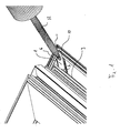
- Figure 1 is schematically the corner of a window sash reproduced, the one of interest here Area is the corner of a rollover bar; mutatis mutandis the reinforcement according to the invention of the corner region and the Protection of the miter cut but also in the corner area a glazing ridge done.
- the two assembled frame legs are through the miter cut 11 separated from each other and show inside pointing webs 10, which in the following because of their Arrangement on the outer frame leg area as outer webs be designated; opposite these webs, and the outer webs 10 parallel, internal webs 9 are arranged.
- the deposit component 1 has an end region, the symmetrically the abutting outer webs 10th interpreted, as well as an opposite area, which the Stege 9 underlined. This covers the deposit component the miter 11 and lies with the top portion. 2 under the bridge 9 on the wall of the underlying groove at.
- the depository member 1 is a non-circular opening 6 formed, in which a rotary tool, for example a Screwdriver, can be used with its help the deposit component from an unillustrated starting position screwed into the illustrated end position becomes; the hatching on the longitudinal sides of the deposit component 1 indicates that these margins are light are inwardly inflected, so that thereby the depository component a certain elasticity in the vertical direction is awarded to the level of the deposit component, so that the deposit component by screwing in his End position jammed under the webs 9 and 10.
- a rotary tool for example a Screwdriver
- this inflection serves to create a Cavity between depository component and corner area with Gehrungsfuge, through the opening 6 by means of an injection molding tool 12 adhesive material can be introduced, the on the one hand the deposit component permanently fixed and on the other hand, the miter joint 11 seals gas-tight and watertight.
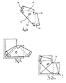
- FIG. 2 shows in detail the depository component according to the invention 1, as used in Figure 1, again.
- the deposit component has two opposite ones Margins 4 on; the end region 5 is for storage formed in the corner of the frame profiles, while the opposite End area 2/3 to the submission of the / opposite webs (s) 9 is formed according to Figure 1.
- the end portion 2 is approximately triangular in shape, wherein the straight edge 2a with the center line through the Deposit component or with the side edges 4 an angle of 45 °.
- a non-circular opening 6 is formed, which for a Intervention for a tool as described in FIG. 1, is formed, and on the other for the injection of adhesive serves.
- This opening is preferably with a bead 7 surrounded, which facilitates the introduction of the tool and Promotes clean working when injecting the adhesive.
- Exemplary dimensions of such a depository component for practical use are: total length about 35 mm, Width in the middle area about 14 mm; the open space below the center line of the component, which is curved by the Training is about 1 mm high.
- FIG. 3 shows another embodiment of a Deposit component for use in one Internal corner, for example on the frame.
- the component has a butterfly-like Shape.
- On the median line after the proper Insertion with the miter joint is flush, one end is rectangular notch 13 is provided, which arranged such is that by continuing the said center line halved; the rectangular incision 13th Opposite baseline 15 goes to the two diegelekken 14 rounded over so that this depository component over the tool engaging in the non-circular opening 6 according to Figures 3b and 3c in the end position by a rotary-sliding movement can be brought and under the jetties and 9 and 10 locked.
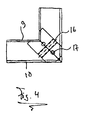
- FIG. 4 shows an embodiment in particular characterized in that the deposit component in the longitudinal direction in itself against a restoring force is shortenable; this is, in the rest of the analog version to the previously described embodiments, the central area 16 fauxpreßbar, for example, by an intermediately stored elastic or resilient element 16, such trained with a tool on the approach holes or Ansatznoppen 17 of the corner angle compressed during assembly, introduced into the corner area and left out so that the angle is at its original length expands and thereby the webs 9 and 10 underlined.
- an intermediately stored elastic or resilient element 16 such trained with a tool on the approach holes or Anthesisnoppen 17 of the corner angle compressed during assembly, introduced into the corner area and left out so that the angle is at its original length expands and thereby the webs 9 and 10 underlined.
- FIG. 5 shows a further embodiment of the invention Deposit component, which in the cases of Use comes in which the profile has no support bar, which the end region 5 of the component can underpin, like this, for example, in internal corners (for example, in Frame or at the glass web of wings) is the case.
- the end portion 5 as angled leg 5a formed, for example at an angle of about 90 °, which is supported on an adjacent web 18.
Abstract
Description
Die Erfindung betrifft ein Hinterlegungsbauteil zur
Stabilisierung und Höhenangleichung von aneinander stoßenden
Flächen von Rahmenprofilen nach dem Oberbegriff des
Anspruchs 1.The invention relates to a deposit component for
Stabilization and height equalization of abutting oneself
Surfaces of frame profiles according to the generic term of
Ein derartiges Hinterlegungsbauteil ist aus der DE 2609388 bekannt.Such a deposit component is known from DE 2609388 known.
Rahmenprofile insbesondere aus Aluminium werden in der Bauwirtschaft in großen Umfang insbesondere bei Fenstern verwendet. Hierbei werden üblicherweise die Rahmen aus Rahmenschenkeln zusammengefügt, wobei die Rahmenschenkel aus beliebig langen extrudierten Profilen auf Gehrung zugeschnitten und zusammengesetzt werden.Frame profiles, in particular made of aluminum, are used in the Construction industry on a large scale, especially in windows used. This is usually the frame Frame legs joined together, the frame legs off any length of extruded profiles mitred tailored and assembled.
Im Bereich der Eckverbindung bzw. des Gehrungsschnittes besteht zum einen das Problem, die aneinander stoßenden Ebenen planar aneinanderzufügen, und es ist zum anderen erwünscht, diese Eckbereiche zur Erhöhung der Stabilität der Eckverbindung zu verstärken. Zu diesem Zweck wird ein Hinterlegungsbauteil vorgesehen.In the area of the corner joint or the Miter cut there is the one problem, the planar join together abutting planes, and it On the other hand, it is desirable to increase these corner areas strengthen the stability of the corner joint. To this Purpose is a depository component provided.
Die der Erfindung zugrunde liegende Aufgabe besteht
darin, ein Hinterlegungsbauteil nach dem Oberbegriff des
Anspruchs 1 zu schaffen, das nicht während sondern nach dem
Zusammenfügen der Rahmenprofile auf einfache Weise
einbringbar ist.The object underlying the invention is
therein, a deposit component according to the preamble of
Diese Aufgabe wird durch die Merkmale des Anspruchs 1
gelöst.This object is achieved by the features of
Das erfindungsgemäße Hinterlegungsbauteil ist somit derart gestaltet, dass eine Verdrehung über die Rast- oder Verriegelungsstellung hinaus nicht erfolgen kann und der Verlauf der Eindrehkurve ein selbsttätiges Rückdrehen verhindert.The depository component according to the invention is thus designed such that a rotation on the catch or Locking position can not be done and the Course of the Eindrehkurve an automatic reverse rotation prevented.
Weitere vorteilhafte Ausgestaltungen des
erfindungsgemäßen Hinterlegungsbauteils sind Gegenstand der
Ansprüche 2 bis 7.Further advantageous embodiments of
Depository component according to the invention are the subject of
Die Erfindung wird anhand der folgenden Figuren näher
erläutert. Hierbei zeigen
Fig. 5 eine weitere Ausführungsform des erfindungsgemäßen Hinterlegungsbauteil in einer Draufsicht in der eingerasteten Position.Fig. 5 shows another embodiment of the Deposit component according to the invention in a plan view in the locked position.
In Figur 1 wird schematisch der Eckbereich eines Fensterflügels wiedergegeben, wobei der hier interessierende Bereich die Ecke eines Überschlagsteges ist; sinngemäß kann die erfindungsgemäße Verstärkung des Eckbereichs und der Absicherung des Gehrungsschnitts aber auch im Eckbereich eines Verglasungssteges erfolgen.In Figure 1 is schematically the corner of a window sash reproduced, the one of interest here Area is the corner of a rollover bar; mutatis mutandis the reinforcement according to the invention of the corner region and the Protection of the miter cut but also in the corner area a glazing ridge done.
Die beiden zusammengefügten Rahmenschenkel sind durch
den Gehrungsschnitt 11 voneinander getrennt und weisen nach
innen weisende Stege 10 auf, die im folgenden wegen ihrer
Anordnung am äußeren Rahmenschenkelbereich als äußere Stege
bezeichnet werden; diesen Stegen gegenüberliegend, und den
äußeren Stegen 10 parallel, sind innenliegende Stege 9 angeordnet.The two assembled frame legs are through
the
Das Hinterlegungsbauteil 1 weist einen Endbereich auf,
der symetrisch die aneinander stoßenden äußeren Stege 10
unterfasst, sowie einen gegenüberliegenden Bereich, der die
Stege 9 unterfasst. Hierbei überdeckt das Hinterlegungsbauteil
die Gehrungsfuge 11 und liegt mit dem Spitzenbereich 2
unter dem Steg 9 an der Wandung der darunterliegende Rille
an.The
In dem Hinterlegungsbauteil 1 ist eine unrunde Öffnung
6 ausgebildet, in die ein Drehwerkzeug, beispielsweise ein
Schraubenzieher, eingesetzt werden kann, mit dessen Hilfe
das Hinterlegungsbauteil aus einer nicht abgebildeten Ausgangsposition
in die abgebildete Endposition eingedreht
wird; die Schraffierung an den Längsseiten des Hinterlegungsbauteils
1 soll andeuten, daß diese Seitenränder leicht
nach innen eingebogen sind, so daß hierdurch dem Hinterlegungsbauteil
eine gewisse Elastizität in senkrechter Richtung
zur Ebene des Hinterlegungsbauteils verliehen wird, so
daß das Hinterlegungsbauteil durch das Eindrehen in seine
Endposition unter den Stegen 9 und 10 verklemmt.In the
Insbesondere dient diese Einbiegung der Schaffung eines
Hohlraums zwischen Hinterlegungsbauteil und Eckbereich mit
Gehrungsfuge, in den durch die Öffnung 6 mittels eines Spritzwerkzeugs
12 Klebematerial eingebracht werden kann, das
zum einen das Hinterlegungsbauteil nachhaltig fixiert und
zum anderen die Gehrungsfuge 11 gas- und wasserdicht abdichtet.In particular, this inflection serves to create a
Cavity between depository component and corner area with
Gehrungsfuge, through the opening 6 by means of an
Figur 2 gibt im einzelnen den erfindungsgemäßen Hinterlegungsbauteil
1, wie er in Figur 1 eingesetzt ist, wieder.FIG. 2 shows in detail the depository component according to the
Hierbei weist das Hinterlegungsbauteil zwei sich gegenüberliegende
Ränder 4 auf; der Endbereich 5 ist zur Lagerung
in der Ecke der Rahmenprofile ausgebildet, während der gegenüberliegende
Endbereich 2/3 zur Unterfassung des/der
gegenüberliegenden Stege(s) 9 gemäß Figur 1 ausgebildet ist.
Hierbei ist der Endbereich 2 etwa dreiecksförmig ausgebildet,
wobei die gerade Kante 2a mit der Mittellinie durch das
Hinterlegungsbauteil bzw. mit den Seitenkanten 4 einen Winkel
von 45° bildet. In der Fläche des Hinterlegungsbauteils
1 ist eine unrunde Öffnung 6 ausgebildet, die zum einen zum
Eingriff für ein Werkzeug, wie bei Figur 1 beschrieben,
ausgebildet ist, und zum anderen zum Einspritzen von Klebstoff
dient. Bevorzugt ist diese Öffnung mit einer Wulst 7
umgeben, die die Einführung des Werkzeugs erleichtert und
sauberes Arbeiten beim Einspritzen des Klebstoffs fördert.In this case, the deposit component has two opposite ones
Margins 4 on; the
Gemäß Figur 2a, bei der die Bezugszeichen die zuvor
gegebene Bedeutung besetzen, ist das Hinterlegungsbauteil
nicht plan sondern insich gebogen ausgebildet; ebenso können
lediglich die Kanten 4, wie in Figur 1 beschrieben, nach
innen abgegebogen sein. Hierdurch kann das erfindungsgemäße
Hinterlegungsbauteil in Richtung senkrecht zur Ebene des
Winkels in gewissem Umfang elastisch sein und während der
Montage etwas aufgespreizt werden, um sich in der Endposition
unter den Stegen 9 und 10 gemäß Figur 1 zu verriegeln.
Insbesondere wird aber durch diese spezielle Verformung
unter dem Hinterlegungsbauteil über der Gehrungsfuge ein
Hohlraum geschaffen, in den Klebemittel eingespritzt werden
kann. Bevorzugt ist das Ende 5 im Randbereich etwas gebogen,
um etwas leichteres Ansetzen unter den Steg zu ermöglichen,
wie in Figur 2b schematisch dargestellt.According to Figure 2a, in which the reference numerals previously
occupy given meaning, is the depository component
not planed but designed to be curved; as well
only the
Beispielhafte Maße eines solchen Hinterlegungsbauteils für den praktischen Einsatz sind: Gesamtlänge etwa 35 mm, Breite im mittleren Bereich etwa 14 mm; der Freiraum unterhalb der Mittellinie des Bauteils, der durch die gebogene Ausbildung entsteht, ist etwa 1 mm hoch.Exemplary dimensions of such a depository component for practical use are: total length about 35 mm, Width in the middle area about 14 mm; the open space below the center line of the component, which is curved by the Training is about 1 mm high.
Figur 3 zeigt eine andere Ausführungsform eines
Hinterlegungsbauteils für Anwendung in einer
Innenecke, beispielsweise am Blendrahmen. Bei dieser Ausführungsform
hat das Bauteil eine schmetterlingsähnliche
Form. Auf der Mittellinie, die nach dem ordnungsgemäßen
Einsetzen mit der Gehrungsfuge fluchtet, ist endseitig eine
rechtwinklige Einkerbung 13 vorgesehen, die derart angeordnet
ist, daß sie durch die Fortführung der genannten Mittellinie
halbiert wird; die dem rechtwinkligen Einschnitt 13
gegenüberliegende Grundlinie 15 geht an den beiden Flügelekken
14 abgerundet derart über, daß dieser Hinterlegungsbauteil
über das in die unrunde Öffnung 6 eingreifende Werkzeug
gemäß Figuren 3b und 3c in die Endstellung durch eine Dreh-Schiebebewegung
gebracht werden kann und unter den Stegen
und 9 und 10 verriegelt.FIG. 3 shows another embodiment of a
Deposit component for use in one
Internal corner, for example on the frame. In this embodiment
the component has a butterfly-like
Shape. On the median line, after the proper
Insertion with the miter joint is flush, one end is
Figur 4 gibt eine Ausführungsform wieder, die im besonderen
dadurch gekennzeichnet ist, daß das Hinterlegungsbauteil
in Längsrichtung in sich gegen eine Rückstellkraft
verkürzbar ist; hierbei ist, in im übrigen analoger Ausführung
zu den vorher beschriebenen Ausführungsformen, der Mittelbereich
16 zusammenpreßbar, beispielsweise durch ein zwischengelagertes
elastisches oder federndes Element 16, derart
ausgebildet, das mit einem Werkzeug über die Ansatzlöcher
oder Ansatznoppen 17 der Eckwinkel bei Montage zusammengedrückt,
in den Eckbereich eingeführt und ausgelassen
wird, so daß sich der Winkel auf seine ursprüngliche Länge
ausdehnt und hierbei die Stege 9 und 10 unterfasst.FIG. 4 shows an embodiment in particular
characterized in that the deposit component
in the longitudinal direction in itself against a restoring force
is shortenable; this is, in the rest of the analog version
to the previously described embodiments, the
Figur 5 zeigt eine weitere Ausführungsform des erfindungsgemäßen
Hinterlegungsbauteils, das in den Fällen zum
Einsatz kommt, bei denen das Profil keinen Stützsteg aufweist,
den der Endbereich 5 des Bauteils unterfassen kann,
wie dieses beispielsweise bei Innenecken (zum Beispiel bei
Blendrahmen oder am Glassteg von Flügeln) der Fall ist.
Hierbei ist der Endbereich 5 als angewinkelter Schenkel 5a
ausgebildet, beispielsweise unter einem Winkel von etwa 90°,
der sich an einem benachbarten Steg 18 abstützt.FIG. 5 shows a further embodiment of the invention
Deposit component, which in the cases of
Use comes in which the profile has no support bar,
which the
Claims (7)
- An underlay assembly for stabilization and height equalization of abutting frame profile surfaces, which is designed as a flat assembly and is of a shape and size to engage or lock underneath opposing ribs (9, 10) that are arranged in the abutment area of the surfaces, one end area (5) of which is conformed for clasping underneath the corner area of the outer ribs (10) of the frame profile that abut each other, wherein the opposing end area (2, 3) thereof is conformed for clasping engagement underneath the opposing, inner abutting ribs (9) of the frame profile, and wherein means (6) are provided on the underlay assembly for installing or mounting a tool that can be used to bring the underlay assembly into the engaging or locking end position covering the mitered cutout, characterized in that it has two edges (4) extending along the length of the underlay assembly, wherein a first edge (4) adjoins a tapered area (2) in the end area (2, 3) for clasping engagement underneath the opposing, inner abutting ribs (9), which tapered area includes a straight edge (2a) that forms an angle of 45° with the edge area, wherein the edge (2a) adjoins an area (3) shaped like part of a circle, which in turn adjoins the second edge 4, and wherein the two edges (4) combine to form a partial circle in the tapered end area (5) for clasping under the corner area of the outer, abutting ribs (10), which end area is provided to lie flush in the corner of the frame profile.
- The underlay assembly according to claim 1, characterized in that it is conformed to engage or lock underneath the ribs (9, 10) and at the same time to cover the mitred joint.
- The underlay assembly according to claim 1, characterized in that the opposing side areas of the edges (4) are curved slightly downwards.
- The underlay assembly according to claim 3, characterized in that a non-circular opening (6) is conformed in the surface of the underlay assembly (1) for introducing the turning tool.
- The underlay assembly according to claim 4, characterized in that the opening (6) is surrounded by a bead (7).
- The underlay assembly according to claim 1, characterized in that it is conformed to be retractable in its lengthwise direction against the restoring force of an elastic or spring-loaded element (16), wherein the means (17) for engaging a tool is conformed on the surface of the underlay assembly, via which the underlay assembly can be pressed together in the lengthwise direction during assembly.
- The underlay assembly according to any of the preceding claims, characterized in that the end area (5) is conformed as an angled leg (5a), which extends essentially perpendicularly to the longitudinal axis of the assembly, and is conformed for clasping underneath an adjacent profile rib (18).
Applications Claiming Priority (2)
| Application Number | Priority Date | Filing Date | Title |
|---|---|---|---|
| DE10126278A DE10126278C2 (en) | 2001-05-29 | 2001-05-29 | deposit component |
| DE10126278 | 2001-05-29 |
Publications (3)
| Publication Number | Publication Date |
|---|---|
| EP1262622A2 EP1262622A2 (en) | 2002-12-04 |
| EP1262622A3 EP1262622A3 (en) | 2003-11-05 |
| EP1262622B1 true EP1262622B1 (en) | 2005-09-28 |
Family
ID=7686610
Family Applications (1)
| Application Number | Title | Priority Date | Filing Date |
|---|---|---|---|
| EP02008949A Expired - Lifetime EP1262622B1 (en) | 2001-05-29 | 2002-04-22 | Underlying structural member |
Country Status (4)
| Country | Link |
|---|---|
| EP (1) | EP1262622B1 (en) |
| AT (1) | ATE305560T1 (en) |
| DE (2) | DE10126278C2 (en) |
| ES (1) | ES2249509T3 (en) |
Families Citing this family (4)
| Publication number | Priority date | Publication date | Assignee | Title |
|---|---|---|---|---|
| DE10217574B3 (en) * | 2002-04-19 | 2004-02-19 | Welser Profile Ag | Kit with corner connector |
| DE202010008917U1 (en) * | 2010-10-28 | 2012-01-30 | SCHÜCO International KG | Frame construction and insertion tool |
| CN104832049A (en) * | 2015-04-02 | 2015-08-12 | 佛山市爵豹机械设备有限公司 | Door and window sleeve |
| FR3041369B1 (en) * | 2015-09-17 | 2018-03-02 | Atlantem Ind | JOINED JOINERY FRAMEWORK AND METHOD OF MANUFACTURING THE SAME |
Family Cites Families (4)
| Publication number | Priority date | Publication date | Assignee | Title |
|---|---|---|---|---|
| DE2226409C3 (en) * | 1972-05-31 | 1980-11-20 | Schueco Heinz Schuermann Gmbh & Co, 4800 Bielefeld | Connector for profiles or pipes |
| DE2609388C3 (en) * | 1976-03-06 | 1980-02-14 | W. Hartmann & Co (Gmbh & Co), 2000 Hamburg | Stabilizing and alignment element for miter joints between two construction profiles |
| DE29910478U1 (en) * | 1998-06-19 | 1999-11-11 | Hartmann & Co W | Fastener |
| ITRN990011A1 (en) * | 1999-04-30 | 2000-10-30 | L M Dei F Lli Monticelli S R L | APPARATUS AND METHOD FOR CONNECTION OF PROFILE ELEMENTS IN CONDITION OF COPLANARITY AND MUTUAL SOLIDARITY, IN THE MANUFACTURE OF CANVAS |
-
2001
- 2001-05-29 DE DE10126278A patent/DE10126278C2/en not_active Expired - Fee Related
-
2002
- 2002-04-22 ES ES02008949T patent/ES2249509T3/en not_active Expired - Lifetime
- 2002-04-22 EP EP02008949A patent/EP1262622B1/en not_active Expired - Lifetime
- 2002-04-22 AT AT02008949T patent/ATE305560T1/en active
- 2002-04-22 DE DE50204365T patent/DE50204365D1/en not_active Expired - Lifetime
Also Published As
| Publication number | Publication date |
|---|---|
| DE50204365D1 (en) | 2006-02-09 |
| ES2249509T3 (en) | 2006-04-01 |
| EP1262622A3 (en) | 2003-11-05 |
| DE10126278C2 (en) | 2003-06-12 |
| ATE305560T1 (en) | 2005-10-15 |
| EP1262622A2 (en) | 2002-12-04 |
| DE10126278A1 (en) | 2002-12-19 |
Similar Documents
| Publication | Publication Date | Title |
|---|---|---|
| EP2520737B1 (en) | Construction panel with a device for connection with at least one further construction panel on a base | |
| EP1033273A2 (en) | Foldable top for motor vehicle provided with an exterior top cover and comprising at least a glass panel | |
| EP1262622B1 (en) | Underlying structural member | |
| DE102014102465B4 (en) | switch cabinet | |
| EP0724061B1 (en) | Connecting element | |
| DE19615378A1 (en) | Sealing body for window or door profiles | |
| DE3611487C2 (en) | ||
| DE19828382C2 (en) | Arrangement for fastening a post having a hollow cross section to the window frame of a window or a door made of plastic or light metal | |
| DE2609388B2 (en) | Stabilization and alignment element for miter joints between two construction profiles | |
| DE102007024250A1 (en) | Excerpt profile for window panel | |
| EP2687650A1 (en) | Construction panel with a device for connection with at least one further construction panel on a base | |
| DE2231577A1 (en) | PACKAGING REAR FIXING OF THE FURNITURE | |
| EP0215937B1 (en) | Hollow profile material for the construction of support mounts and frames | |
| DE3609992C2 (en) | Door frame for sheathing metal frames | |
| DE4308955C2 (en) | Angle piece for a frame or sash for the adjustable mounting of a close-meshed insect screen | |
| EP0033491B1 (en) | Frame for structures, in particular for show cases and show cabinets | |
| DE4042660C2 (en) | Hollow profiled double glazing bar | |
| DE2814953A1 (en) | Detachable window profile frame to base frame fixture - involves transverse screw through slit dividing serrated bolt shaft (OE 15.8.78) | |
| EP2754838B1 (en) | Frame or T-shaped joints | |
| EP1052166A2 (en) | Arrangement for the attachment of a plastic sheet at a frame, particularly at a flange of a car body | |
| DE2507393A1 (en) | Roller sliding door and window sectioned frame - has H-sectioned components with screws between clamping battens on roller carriers | |
| DE2004189A1 (en) | Frame profile with insert profile | |
| DE102021131887A1 (en) | Building opening-closing element | |
| DE19800375C1 (en) | Ground mounting for wooden paving panels | |
| DE202007008187U1 (en) | Excerpt profile for window panel |
Legal Events
| Date | Code | Title | Description |
|---|---|---|---|
| PUAI | Public reference made under article 153(3) epc to a published international application that has entered the european phase |
Free format text: ORIGINAL CODE: 0009012 |
|
| AK | Designated contracting states |
Kind code of ref document: A2 Designated state(s): AT BE CH CY DE DK ES FI FR GB GR IE IT LI LU MC NL PT SE TR |
|
| AX | Request for extension of the european patent |
Free format text: AL;LT;LV;MK;RO;SI |
|
| RAP1 | Party data changed (applicant data changed or rights of an application transferred) |
Owner name: NORSK HYDRO ASA |
|
| PUAL | Search report despatched |
Free format text: ORIGINAL CODE: 0009013 |
|
| AK | Designated contracting states |
Kind code of ref document: A3 Designated state(s): AT BE CH CY DE DK ES FI FR GB GR IE IT LI LU MC NL PT SE TR |
|
| AX | Request for extension of the european patent |
Extension state: AL LT LV MK RO SI |
|
| RIC1 | Information provided on ipc code assigned before grant |
Ipc: 7E 06B 3/964 A Ipc: 7E 06B 3/96 B |
|
| 17P | Request for examination filed |
Effective date: 20031125 |
|
| 17Q | First examination report despatched |
Effective date: 20040209 |
|
| AKX | Designation fees paid |
Designated state(s): AT BE CH CY DE DK ES FI FR GB GR IE IT LI LU MC NL PT SE TR |
|
| GRAP | Despatch of communication of intention to grant a patent |
Free format text: ORIGINAL CODE: EPIDOSNIGR1 |
|
| GRAS | Grant fee paid |
Free format text: ORIGINAL CODE: EPIDOSNIGR3 |
|
| GRAA | (expected) grant |
Free format text: ORIGINAL CODE: 0009210 |
|
| AK | Designated contracting states |
Kind code of ref document: B1 Designated state(s): AT BE CH CY DE DK ES FI FR GB GR IE IT LI LU MC NL PT SE TR |
|
| PG25 | Lapsed in a contracting state [announced via postgrant information from national office to epo] |
Ref country code: FI Free format text: LAPSE BECAUSE OF FAILURE TO SUBMIT A TRANSLATION OF THE DESCRIPTION OR TO PAY THE FEE WITHIN THE PRESCRIBED TIME-LIMIT Effective date: 20050928 |
|
| REG | Reference to a national code |
Ref country code: GB Ref legal event code: FG4D Free format text: NOT ENGLISH |
|
| REG | Reference to a national code |
Ref country code: CH Ref legal event code: EP |
|
| REG | Reference to a national code |
Ref country code: IE Ref legal event code: FG4D Free format text: LANGUAGE OF EP DOCUMENT: GERMAN |
|
| GBT | Gb: translation of ep patent filed (gb section 77(6)(a)/1977) |
Effective date: 20051129 |
|
| PG25 | Lapsed in a contracting state [announced via postgrant information from national office to epo] |
Ref country code: DK Free format text: LAPSE BECAUSE OF FAILURE TO SUBMIT A TRANSLATION OF THE DESCRIPTION OR TO PAY THE FEE WITHIN THE PRESCRIBED TIME-LIMIT Effective date: 20051228 Ref country code: GR Free format text: LAPSE BECAUSE OF FAILURE TO SUBMIT A TRANSLATION OF THE DESCRIPTION OR TO PAY THE FEE WITHIN THE PRESCRIBED TIME-LIMIT Effective date: 20051228 |
|
| REG | Reference to a national code |
Ref country code: CH Ref legal event code: NV Representative=s name: E. BLUM & CO. PATENTANWAELTE |
|
| REG | Reference to a national code |
Ref country code: SE Ref legal event code: TRGR |
|
| REF | Corresponds to: |
Ref document number: 50204365 Country of ref document: DE Date of ref document: 20060209 Kind code of ref document: P |
|
| REG | Reference to a national code |
Ref country code: ES Ref legal event code: FG2A Ref document number: 2249509 Country of ref document: ES Kind code of ref document: T3 |
|
| PG25 | Lapsed in a contracting state [announced via postgrant information from national office to epo] |
Ref country code: MC Free format text: LAPSE BECAUSE OF NON-PAYMENT OF DUE FEES Effective date: 20060430 |
|
| ET | Fr: translation filed | ||
| PLBE | No opposition filed within time limit |
Free format text: ORIGINAL CODE: 0009261 |
|
| STAA | Information on the status of an ep patent application or granted ep patent |
Free format text: STATUS: NO OPPOSITION FILED WITHIN TIME LIMIT |
|
| 26N | No opposition filed |
Effective date: 20060629 |
|
| REG | Reference to a national code |
Ref country code: CH Ref legal event code: PFA Owner name: NORSK HYDRO ASA Free format text: NORSK HYDRO ASA#BYGDOY ALLE 2#0257 OSLO 2 (NO) -TRANSFER TO- NORSK HYDRO ASA#BYGDOY ALLE 2#0257 OSLO 2 (NO) |
|
| PG25 | Lapsed in a contracting state [announced via postgrant information from national office to epo] |
Ref country code: LU Free format text: LAPSE BECAUSE OF NON-PAYMENT OF DUE FEES Effective date: 20060422 Ref country code: TR Free format text: LAPSE BECAUSE OF FAILURE TO SUBMIT A TRANSLATION OF THE DESCRIPTION OR TO PAY THE FEE WITHIN THE PRESCRIBED TIME-LIMIT Effective date: 20050928 |
|
| PG25 | Lapsed in a contracting state [announced via postgrant information from national office to epo] |
Ref country code: CY Free format text: LAPSE BECAUSE OF FAILURE TO SUBMIT A TRANSLATION OF THE DESCRIPTION OR TO PAY THE FEE WITHIN THE PRESCRIBED TIME-LIMIT Effective date: 20050928 |
|
| PGFP | Annual fee paid to national office [announced via postgrant information from national office to epo] |
Ref country code: PT Payment date: 20100416 Year of fee payment: 9 |
|
| PGFP | Annual fee paid to national office [announced via postgrant information from national office to epo] |
Ref country code: SE Payment date: 20110414 Year of fee payment: 10 Ref country code: ES Payment date: 20110426 Year of fee payment: 10 Ref country code: IE Payment date: 20110426 Year of fee payment: 10 Ref country code: FR Payment date: 20110510 Year of fee payment: 10 |
|
| PGFP | Annual fee paid to national office [announced via postgrant information from national office to epo] |
Ref country code: GB Payment date: 20110421 Year of fee payment: 10 Ref country code: AT Payment date: 20110414 Year of fee payment: 10 Ref country code: NL Payment date: 20110426 Year of fee payment: 10 |
|
| PGFP | Annual fee paid to national office [announced via postgrant information from national office to epo] |
Ref country code: IT Payment date: 20110421 Year of fee payment: 10 |
|
| REG | Reference to a national code |
Ref country code: PT Ref legal event code: MM4A Free format text: LAPSE DUE TO NON-PAYMENT OF FEES Effective date: 20111024 |
|
| PG25 | Lapsed in a contracting state [announced via postgrant information from national office to epo] |
Ref country code: PT Free format text: LAPSE BECAUSE OF NON-PAYMENT OF DUE FEES Effective date: 20111024 |
|
| REG | Reference to a national code |
Ref country code: NL Ref legal event code: V1 Effective date: 20121101 |
|
| REG | Reference to a national code |
Ref country code: SE Ref legal event code: EUG |
|
| REG | Reference to a national code |
Ref country code: AT Ref legal event code: MM01 Ref document number: 305560 Country of ref document: AT Kind code of ref document: T Effective date: 20120422 |
|
| GBPC | Gb: european patent ceased through non-payment of renewal fee |
Effective date: 20120422 |
|
| REG | Reference to a national code |
Ref country code: IE Ref legal event code: MM4A |
|
| REG | Reference to a national code |
Ref country code: FR Ref legal event code: ST Effective date: 20121228 |
|
| PG25 | Lapsed in a contracting state [announced via postgrant information from national office to epo] |
Ref country code: IE Free format text: LAPSE BECAUSE OF NON-PAYMENT OF DUE FEES Effective date: 20120422 Ref country code: AT Free format text: LAPSE BECAUSE OF NON-PAYMENT OF DUE FEES Effective date: 20120422 Ref country code: GB Free format text: LAPSE BECAUSE OF NON-PAYMENT OF DUE FEES Effective date: 20120422 |
|
| PG25 | Lapsed in a contracting state [announced via postgrant information from national office to epo] |
Ref country code: SE Free format text: LAPSE BECAUSE OF NON-PAYMENT OF DUE FEES Effective date: 20120423 Ref country code: IT Free format text: LAPSE BECAUSE OF NON-PAYMENT OF DUE FEES Effective date: 20120422 Ref country code: FR Free format text: LAPSE BECAUSE OF NON-PAYMENT OF DUE FEES Effective date: 20120430 |
|
| PG25 | Lapsed in a contracting state [announced via postgrant information from national office to epo] |
Ref country code: NL Free format text: LAPSE BECAUSE OF NON-PAYMENT OF DUE FEES Effective date: 20121101 |
|
| REG | Reference to a national code |
Ref country code: ES Ref legal event code: FD2A Effective date: 20131030 |
|
| PG25 | Lapsed in a contracting state [announced via postgrant information from national office to epo] |
Ref country code: ES Free format text: LAPSE BECAUSE OF NON-PAYMENT OF DUE FEES Effective date: 20120423 |
|
| REG | Reference to a national code |
Ref country code: DE Ref legal event code: R082 Ref document number: 50204365 Country of ref document: DE Representative=s name: KOTITSCHKE & HEURUNG PARTNERSCHAFT MBB PATENT-, DE |
|
| PGFP | Annual fee paid to national office [announced via postgrant information from national office to epo] |
Ref country code: CH Payment date: 20140418 Year of fee payment: 13 |
|
| REG | Reference to a national code |
Ref country code: CH Ref legal event code: PUE Owner name: SAPA AS, NO Free format text: FORMER OWNER: NORSK HYDRO ASA, NO |
|
| REG | Reference to a national code |
Ref country code: DE Ref legal event code: R082 Ref document number: 50204365 Country of ref document: DE Representative=s name: KOTITSCHKE & HEURUNG PARTNERSCHAFT MBB PATENT-, DE |
|
| REG | Reference to a national code |
Ref country code: DE Ref legal event code: R082 Ref document number: 50204365 Country of ref document: DE Effective date: 20140109 Ref country code: DE Ref legal event code: R082 Ref document number: 50204365 Country of ref document: DE Representative=s name: KOTITSCHKE & HEURUNG PARTNERSCHAFT MBB PATENT-, DE Effective date: 20141017 Ref country code: DE Ref legal event code: R082 Ref document number: 50204365 Country of ref document: DE Representative=s name: KOTITSCHKE & HEURUNG PARTNERSCHAFT MBB PATENT-, DE Effective date: 20140109 Ref country code: DE Ref legal event code: R081 Ref document number: 50204365 Country of ref document: DE Owner name: SAPA AS, NO Free format text: FORMER OWNER: NORSK HYDRO ASA, OSLO, NO Effective date: 20141017 |
|
| REG | Reference to a national code |
Ref country code: DE Ref legal event code: R082 Ref document number: 50204365 Country of ref document: DE |
|
| REG | Reference to a national code |
Ref country code: CH Ref legal event code: PL |
|
| PG25 | Lapsed in a contracting state [announced via postgrant information from national office to epo] |
Ref country code: CH Free format text: LAPSE BECAUSE OF NON-PAYMENT OF DUE FEES Effective date: 20150430 Ref country code: LI Free format text: LAPSE BECAUSE OF NON-PAYMENT OF DUE FEES Effective date: 20150430 |
|
| PGFP | Annual fee paid to national office [announced via postgrant information from national office to epo] |
Ref country code: DE Payment date: 20210420 Year of fee payment: 20 |
|
| PGFP | Annual fee paid to national office [announced via postgrant information from national office to epo] |
Ref country code: BE Payment date: 20210420 Year of fee payment: 20 |
|
| REG | Reference to a national code |
Ref country code: DE Ref legal event code: R082 Ref document number: 50204365 Country of ref document: DE Representative=s name: EISENFUEHR SPEISER PATENTANWAELTE RECHTSANWAEL, DE |
|
| REG | Reference to a national code |
Ref country code: DE Ref legal event code: R071 Ref document number: 50204365 Country of ref document: DE |
|
| REG | Reference to a national code |
Ref country code: BE Ref legal event code: MK Effective date: 20220422 |