EP1052166A2 - Arrangement for the attachment of a plastic sheet at a frame, particularly at a flange of a car body - Google Patents
Arrangement for the attachment of a plastic sheet at a frame, particularly at a flange of a car body Download PDFInfo
- Publication number
- EP1052166A2 EP1052166A2 EP00107956A EP00107956A EP1052166A2 EP 1052166 A2 EP1052166 A2 EP 1052166A2 EP 00107956 A EP00107956 A EP 00107956A EP 00107956 A EP00107956 A EP 00107956A EP 1052166 A2 EP1052166 A2 EP 1052166A2
- Authority
- EP
- European Patent Office
- Prior art keywords
- arrangement according
- pins
- frame
- disc
- area
- Prior art date
- Legal status (The legal status is an assumption and is not a legal conclusion. Google has not performed a legal analysis and makes no representation as to the accuracy of the status listed.)
- Granted
Links
Images

Classifications
-
- B—PERFORMING OPERATIONS; TRANSPORTING
- B60—VEHICLES IN GENERAL
- B60J—WINDOWS, WINDSCREENS, NON-FIXED ROOFS, DOORS, OR SIMILAR DEVICES FOR VEHICLES; REMOVABLE EXTERNAL PROTECTIVE COVERINGS SPECIALLY ADAPTED FOR VEHICLES
- B60J1/00—Windows; Windscreens; Accessories therefor
- B60J1/004—Mounting of windows
- B60J1/006—Mounting of windows characterised by fixation means such as clips, adhesive, etc.
Definitions
- the invention relates to an arrangement according to the preamble of patent claim 1.
- the invention lies the task of an arrangement for fastening such Creating a plastic disc that does not require the use of an adhesive is easy can be manufactured and canceled and the attachment with structurally simple additions also a cover strip allowed.
- a particular advantage of the invention can be seen in the fact that it is known per se and proven locking devices, such as spreader bars or nuts, washers and sliders, gets along. The same applies to the design of the plug holders for the Cover strip, which is essentially only extensions on the cover strip and with these interacting end-face depressions or peripheral areas on the pins contains.
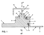
- FIG. 1 If one looks first at FIG. 1, one can see at 1 that of a polycarbonate Manufactured plastic window pane with the edge area 2, which is detachable Attachment to the body flange 3 is formed.
- the body flange 3 is arranged sunk against the body side part 4 such that the outer surface 5 of the disc 1 is aligned with the outer surface 6 of the body side part 4 and so one Forms the outside of the vehicle, which is aerodynamically designed.
- the near-edge pane area 2 at 7 and 8 Has recesses for receiving elastic seals 9 and 10, the gap Seal 11 between pane 1 on the one hand and body on the other.
- a plurality of pins 12 are provided in this embodiment are uniform in material with the disc 1 and perpendicular to the main plane of the same point. They penetrate individual through holes 13 in the body flange 3 and wear on their circumference spreader bars 14, which are after inserting the pin 12 through the through holes 13 behind the body flange 3, so that this between the end faces of the expansion webs 14 on the one hand and the sealing strip 9 on the other is clamped elastically and a movement of the disc 1 of the Body flange away (so down in Figure 1) is prevented. On the other hand is a disassembly of the disc 1 easily by manual or by means of a tool compression of the clamping webs 14 possible.
- the through holes 13 thus have a correspondingly large diameter.
- the screw pin 34 does not carry a screw head, but for attaching one Screwing tool a polygonal profile 35, which at the same time for sliding one with in the shape of the recess 36 provided extension 37 on the cover strip 38 serves.
- an additional component is also shown as Locking means in the form of the pin or slider 40 provided according to the Double arrow 41 on the pin 42, which is again of the same material here, on the disk 43 can be postponed or withdrawn.
- the extension 44 is also here with a Recess 45 provided on the free end of the pin 42 to produce a Clamp connection is pushed on.
Abstract
Description
Die Erfindung betrifft eine Anordnung gemäß dem Oberbegriff des Patentanspruchs 1.The invention relates to an arrangement according to the preamble of patent claim 1.
Vor allem zur Herstellung von Fensterscheiben für Kraftfahrzeug-Karosserien ist es bekannt, Kunststoffe, insbesondere ein Polycarbonat, zu verwenden. Der Erfindung liegt die Aufgabe zugrunde, eine Anordnung zur Befestigung einer derartigen Kunststoffscheibe zu schaffen, die ohne Verwendung eines Klebers auskommt, leicht herstell- und aufhebbar ist und mit konstruktiv einfachen Ergänzungen die Befestigung auch einer Abdeckleiste erlaubt.It is especially for the production of window panes for motor vehicle bodies known to use plastics, especially a polycarbonate. The invention lies the task of an arrangement for fastening such Creating a plastic disc that does not require the use of an adhesive is easy can be manufactured and canceled and the attachment with structurally simple additions also a cover strip allowed.
Die erfindungsgemäße Lösung dieser Aufgabe besteht in den kennzeichnenden Merkmalen des Hauptanspruchs, vorteilhafte Ausbildungen der Erfindung beschreiben die Unteransprüche.The inventive solution to this problem consists in the characterizing Features of the main claim describe advantageous embodiments of the invention the subclaims.
Ein besonderer Vorteil der Erfindung ist darin zu sehen, daß sie mit für sich bekannten und bewährten Arretiermitteln, wie Spreizstegen oder Muttern, Scheiben und Schiebern, auskommt. Entsprechendes gilt für die Ausbildung der Steckhalterungen für die Abdeckleiste, die im wesentlichen nur Fortsätze an der Abdeckleiste und mit diesen zusammenwirkende stirnseitige Vertiefungen oder Umfangsbereiche an den Zapfen enthält.A particular advantage of the invention can be seen in the fact that it is known per se and proven locking devices, such as spreader bars or nuts, washers and sliders, gets along. The same applies to the design of the plug holders for the Cover strip, which is essentially only extensions on the cover strip and with these interacting end-face depressions or peripheral areas on the pins contains.
Drei Ausführungsbeispiele der Erfindung werden im folgenden anhand der Zeichnung erläutert, deren Figuren Horizontalschnitte durch den Befestigungsbereich einer Kraftfahrzeug-Fensterscheibe an einem Karosserieflansch wiedergeben.Three embodiments of the invention are described below with reference to the drawing explained, whose figures are horizontal sections through the fastening area of a Play a motor vehicle window on a body flange.
Betrachtet man zunächst Figur 1, so erkennt man bei 1 die aus einem Polycarbonat
gefertigte Kunststoff-Fensterscheibe mit dem Randbereich 2, der zur lösbaren
Befestigung an dem Karosserieflansch 3 ausgebildet ist. Der Karosserieflansch 3 ist
gegenüber dem Karosserieseitenteil 4 derart versenkt angeordnet, daß die Außenfläche
5 der Scheibe 1 mit der Außenfläche 6 des Karosserieseitenteils 4 fluchtet und so eine
Fahrzeugaußenseite bildet, die strömungsgünstig gestaltet ist.If one looks first at FIG. 1, one can see at 1 that of a polycarbonate
Manufactured plastic window pane with the
Ehe auf die eigentliche Befestigung der Scheibe 1 am Karosserielflansch 3 eingegangen
wird, sei darauf hingewiesen, daß der randnahe Scheibenbereich 2 bei 7 und 8
Vertiefungen zur Aufnahme von elastischen Dichtungen 9 und 10 aufweist, die den Spalt
11 zwischen Scheibe 1 einerseits und Karosserie andererseits abdichten.Before going into the actual attachment of the washer 1 to the
Betrachtet man nun die Mittel zur Befestigung der Scheibe 1 am Karosserieflansch 3, so
sind eine Vielzahl von Zapfen 12 vorgesehen, die in diesem Ausführungsbeispiel
materialeinheitlich mit der Scheibe 1 sind und senkrecht zur Hauptebene derselben
weisen. Sie durchsetzen individuelle Durchstecklöcher 13 im Karosserieflansch 3 und
tragen auf ihrem Umfang Spreizstege 14, die sich nach dem Durchstecken der Zapfen
12 durch die Durchstecklöcher 13 hinter den Karosserielflansch 3 legen, so daß dieser
zwischen den Stirnseiten der Spreizstege 14 einerseits und der Dichtleiste 9 andererseits
gleichsam elastisch eingespannt ist und eine Bewegung der Scheibe 1 von dem
Karosserieflansch weg (in Figur 1 also nach unten) verhindert ist. Auf der anderen Seite
ist eine Demontage der Scheibe 1 leicht durch manuelles oder mittels eines Werkzeugs
vorgenommenes Zusammendrücken der Klemmstege 14 möglich. Die Durchstecklöcher
13 besitzen also einen entsprechend großen Durchmesser.If we now consider the means for fastening the pane 1 to the
In Figur 1 ist durch den Pfeil 15 die Bewegung der Scheibe 1 relativ zum
Karosserieseitenteil 4 bei der Montage der Scheibe, dagegen durch den Pfeil 16 die
entsprechende Relativbewegung bei der Demontage der Scheibe angedeutet.In Figure 1 by
Auf ihren Stirnseiten sind die Zapfen 12 mit Vertiefungen 17 zur klemmenden Aufnahme
von Fortsätzen 18 an der Abdeckleiste 19 versehen, die nach Montage der Scheibe 1 an
dem Karosserieseitenteil 4 aufgesteckt wird. Die entsprechende Bewegung der
Abdeckleiste 19 ist durch den Pfeil 20, ihre Bewegung zur Demontage, die vor der
Demontage der Scheibe 1 (Zusammendrücken der Spreizstege 14) erfolgen muß, durch
den Pfeil 21 angedeutet. On their end faces are the
Während bei dieser Ausführungsform der Erfindung also zur Herstellung der
Befestigungsverbindungen für Scheibe 1 und Abdeckleiste 19 keine zusätzlichen Teile
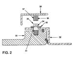
erforderlich sind, ist bei der Ausführungsform nach Figur 2 zur Befestigung der Scheibe
30 an dem wiederum mit Durchstecklöchern 31 versehenen Karosserieflansch 32 eine
Sicherungsscheibe 33 vorgesehen, an deren Stelle auch eine Mutter treten kann und die
nach Durchstecken oder Einschrauben von die Zapfen 12 in Figur 1 ersetzenden
Schraubzapfen 34 auf eine umfangseitige Vertiefung der Schraubzapfen 34 geschoben
oder auf einen Gewindebereich aufgeschraubt wird.So while in this embodiment of the invention for the manufacture of
Fastening connections for disc 1 and
Der Schraubzapfen 34 trägt keinen Schraubenkopf, sondern zum Ansetzen eines
Schraubwerkzeugs ein Mehrkantprofil 35, das zugleich zum Aufschieben eines mit einer
in der Form angepaßten Ausnehmung 36 versehenen Fortsatzes 37 an der Abdeckleiste
38 dient.The
Auch in dem Ausführungsbeispiel nach Figur 3 ist ein zusätzliches Bauteil als
Arretiermittel in Gestalt des Stiftes oder Schiebers 40 vorgesehen, der gemäß dem
Doppelpfeil 41 auf den hier wieder materialeinheitlichen Stift 42 an der Scheibe 43
aufgeschoben bzw. abgezogen werden kann. Auch hier ist der Fortsatz 44 mit einer
Ausnehmung 45 versehen, die auf das freie Ende des Zapfens 42 zur Herstellung einer
Klemmverbindung aufgeschoben wird.In the exemplary embodiment according to FIG. 3, an additional component is also shown as
Locking means in the form of the pin or
Zur Befestigung der Scheibe 43 werden also die verschiedenen Zapfen 42 durch
Durchstecklöcher 46 im Karosserieflansch 47 hindurchgesteckt, dann werden die
Arretiermittel 40 in Figur 3 von rechts nach links auf den mit einer Vertiefung versehenen
Umfang des jeweiligen Zapfens 42 aufgeschoben oder, im Falle eines Sperrstifts, in ein
Querloch des Zapfens 42 eingesetzt, und anschließend wird die Abdeckleiste 48
aufgesteckt. Bei der Demontage erfolgen diese Montageschritte verständlicherweise in
umgekehrter Reihenfolge.The
Mit der Erfindung ist demgemäß eine gattungsgemäße Befestigungsanordnung geschaffen, die montage- und demontagefreundlich ist und deren Konstruktion sich durch Robustheit auszeichnet.With the invention is accordingly a generic mounting arrangement created that is easy to assemble and disassemble and whose construction characterized by robustness.
Claims (12)
Applications Claiming Priority (2)
| Application Number | Priority Date | Filing Date | Title |
|---|---|---|---|
| DE19921481A DE19921481A1 (en) | 1999-05-08 | 1999-05-08 | Arrangement for fastening a plastic pane to a frame, in particular a body flange |
| DE19921481 | 1999-05-08 |
Publications (3)
| Publication Number | Publication Date |
|---|---|
| EP1052166A2 true EP1052166A2 (en) | 2000-11-15 |
| EP1052166A3 EP1052166A3 (en) | 2001-01-17 |
| EP1052166B1 EP1052166B1 (en) | 2006-07-26 |
Family
ID=7907570
Family Applications (1)
| Application Number | Title | Priority Date | Filing Date |
|---|---|---|---|
| EP00107956A Expired - Lifetime EP1052166B1 (en) | 1999-05-08 | 2000-04-17 | Plastic sheet-frame-arrangement with a plastic window sheet and a car body flange of a vehicle forming the frame |
Country Status (3)
| Country | Link |
|---|---|
| EP (1) | EP1052166B1 (en) |
| AT (1) | ATE334037T1 (en) |
| DE (2) | DE19921481A1 (en) |
Families Citing this family (5)
| Publication number | Priority date | Publication date | Assignee | Title |
|---|---|---|---|---|
| US7637554B2 (en) | 2006-10-20 | 2009-12-29 | Exatec Llc | Flush mounted plastic window |
| WO2008051903A2 (en) * | 2006-10-20 | 2008-05-02 | Exatec, Llc | Flush mounted plastic window for vehicles |
| US7758104B2 (en) * | 2007-02-13 | 2010-07-20 | Clark Equipment Company | Window arrangement for a construction vehicle |
| US8091955B2 (en) | 2009-04-16 | 2012-01-10 | Clark Equipment Company | Sliding window for work vehicle cab |
| FR3002495B1 (en) * | 2013-02-26 | 2015-03-20 | Peugeot Citroen Automobiles Sa | WINDSHIELDS OF WHICH AT LEAST THE INNER PART IS CONSISTED OF A TRANSPARENT PLASTIC WALL |
Citations (3)
| Publication number | Priority date | Publication date | Assignee | Title |
|---|---|---|---|---|
| US3819226A (en) * | 1972-10-10 | 1974-06-25 | Coleman Co | Attachment assembly for snowmobile windshield |
| EP0415716A1 (en) * | 1989-08-31 | 1991-03-06 | Hashimoto Forming Industry Co Ltd | Synthetic resin window for automotive vehicles or the like |
| DE19642648A1 (en) * | 1996-10-16 | 1998-04-23 | Volkswagen Ag | Production of window including module carriers by pressure injection moulding |
Family Cites Families (4)
| Publication number | Priority date | Publication date | Assignee | Title |
|---|---|---|---|---|
| DE3333672A1 (en) * | 1983-09-17 | 1985-04-04 | Volkswagenwerk Ag, 3180 Wolfsburg | Holder for a window pane, in particular on a flange of a vehicle body of a motor vehicle |
| IT1183758B (en) * | 1985-02-15 | 1987-10-22 | Comind Spa Azienda Ages | FIXED CRYSTAL FOR MOTOR VEHICLES AND ITS DIRECT AND REVERSIBLE CONNECTION METHOD TO THE VEHICLE BODY |
| DE19835877B4 (en) * | 1997-08-07 | 2006-03-09 | Kabushiki Kaisha Toyota Jidoshokki, Kariya | vehicle window |
| DE19824517A1 (en) * | 1998-06-02 | 1999-12-09 | Fritz Richard Gmbh & Co Kg | Disc or disc unit for insertion into a predetermined opening of a vehicle or the like |
-
1999
- 1999-05-08 DE DE19921481A patent/DE19921481A1/en not_active Ceased
-
2000
- 2000-04-17 DE DE50013211T patent/DE50013211D1/en not_active Expired - Lifetime
- 2000-04-17 AT AT00107956T patent/ATE334037T1/en not_active IP Right Cessation
- 2000-04-17 EP EP00107956A patent/EP1052166B1/en not_active Expired - Lifetime
Patent Citations (3)
| Publication number | Priority date | Publication date | Assignee | Title |
|---|---|---|---|---|
| US3819226A (en) * | 1972-10-10 | 1974-06-25 | Coleman Co | Attachment assembly for snowmobile windshield |
| EP0415716A1 (en) * | 1989-08-31 | 1991-03-06 | Hashimoto Forming Industry Co Ltd | Synthetic resin window for automotive vehicles or the like |
| DE19642648A1 (en) * | 1996-10-16 | 1998-04-23 | Volkswagen Ag | Production of window including module carriers by pressure injection moulding |
Also Published As
| Publication number | Publication date |
|---|---|
| DE19921481A1 (en) | 2000-11-09 |
| ATE334037T1 (en) | 2006-08-15 |
| EP1052166A3 (en) | 2001-01-17 |
| EP1052166B1 (en) | 2006-07-26 |
| DE50013211D1 (en) | 2006-09-07 |
Similar Documents
| Publication | Publication Date | Title |
|---|---|---|
| DE4404348A1 (en) | Process for the production and installation of a glass pane with a frame, in particular on a vehicle part | |
| EP0865813A1 (en) | Filter cartridge with a frame | |
| AT501449B1 (en) | CONNECTING DEVICE FOR CONNECTING COMPONENTS | |
| EP1052166A2 (en) | Arrangement for the attachment of a plastic sheet at a frame, particularly at a flange of a car body | |
| EP1394420B1 (en) | Insert for a wall opening, particularly in a vehicle body | |
| DE2231577A1 (en) | PACKAGING REAR FIXING OF THE FURNITURE | |
| DE3345954A1 (en) | FRUITBED | |
| DE2934215A1 (en) | Fitting for domestic bowl into table top - consists of frame of strips with adhesive compartment | |
| DE102008046850B4 (en) | Support for photovoltaic modules and associated assembly and associated assembly method | |
| DE2507393A1 (en) | Roller sliding door and window sectioned frame - has H-sectioned components with screws between clamping battens on roller carriers | |
| DE1964770A1 (en) | Dismountable box, preferably as a piece of furniture | |
| DE2933712A1 (en) | Right angle corner connector for three frame bars - has plastics cube with metal inserts in sides for screw fixing ends of bars | |
| DE19936306B4 (en) | Worktop and cover plate | |
| DE3740939A1 (en) | Marking unit | |
| DD222366A1 (en) | LID COVER FOR COATED WASHING MACHINES | |
| DE3302820A1 (en) | Changeable frame | |
| DE1797571C3 (en) | Frame for slide film pictures | |
| DE19836435C1 (en) | Door system, especially door intercom system | |
| DE4320285C2 (en) | Spirit level | |
| DE7416216U (en) | Removable frame with a picture arranged between a pane of glass and a picture carrier | |
| DE10209121A1 (en) | Adhesive-free, watertight frame construction for watertight container, especially aquarium, has profile elements that accept continuous seals in which transparent aquarium walls can be fitted without adhesive | |
| DE3530391C1 (en) | Construction element as part of display structures, such as show stands or similar temporary structures | |
| DE19848901C1 (en) | Case made of aluminum or plastic for holding medical emergency equipment, tools, photographic or video equipment comprises lower and upper parts connected to each other by at least one functional component | |
| DE20203260U1 (en) | Arrangement for connecting an assembly carrier to a door panel of a motor vehicle door | |
| WO2002056436A1 (en) | Enclosure, particularly for accommodating electrical and electronic components |
Legal Events
| Date | Code | Title | Description |
|---|---|---|---|
| PUAI | Public reference made under article 153(3) epc to a published international application that has entered the european phase |
Free format text: ORIGINAL CODE: 0009012 |
|
| AK | Designated contracting states |
Kind code of ref document: A2 Designated state(s): AT BE CH CY DE DK ES FI FR GB GR IE IT LI LU MC NL PT SE |
|
| AX | Request for extension of the european patent |
Free format text: AL;LT;LV;MK;RO;SI |
|
| PUAL | Search report despatched |
Free format text: ORIGINAL CODE: 0009013 |
|
| AK | Designated contracting states |
Kind code of ref document: A3 Designated state(s): AT BE CH CY DE DK ES FI FR GB GR IE IT LI LU MC NL PT SE |
|
| AX | Request for extension of the european patent |
Free format text: AL;LT;LV;MK;RO;SI |
|
| 17P | Request for examination filed |
Effective date: 20010717 |
|
| AKX | Designation fees paid |
Free format text: AT BE CH CY DE DK ES FI FR GB GR IE IT LI LU MC NL PT SE |
|
| 17Q | First examination report despatched |
Effective date: 20020322 |
|
| GRAP | Despatch of communication of intention to grant a patent |
Free format text: ORIGINAL CODE: EPIDOSNIGR1 |
|
| RTI1 | Title (correction) |
Free format text: PLASTIC SHEET-FRAME-ARRANGEMENT WITH A PLASTIC WINDOW SHEET AND A CAR BODY FLANGE OF A VEHICLE FORMING THE FRAME |
|
| GRAS | Grant fee paid |
Free format text: ORIGINAL CODE: EPIDOSNIGR3 |
|
| GRAA | (expected) grant |
Free format text: ORIGINAL CODE: 0009210 |
|
| AK | Designated contracting states |
Kind code of ref document: B1 Designated state(s): AT BE CH CY DE DK ES FI FR GB GR IE IT LI LU MC NL PT SE |
|
| PG25 | Lapsed in a contracting state [announced via postgrant information from national office to epo] |
Ref country code: IT Free format text: LAPSE BECAUSE OF FAILURE TO SUBMIT A TRANSLATION OF THE DESCRIPTION OR TO PAY THE FEE WITHIN THE PRESCRIBED TIME-LIMIT;WARNING: LAPSES OF ITALIAN PATENTS WITH EFFECTIVE DATE BEFORE 2007 MAY HAVE OCCURRED AT ANY TIME BEFORE 2007. THE CORRECT EFFECTIVE DATE MAY BE DIFFERENT FROM THE ONE RECORDED. Effective date: 20060726 Ref country code: FI Free format text: LAPSE BECAUSE OF FAILURE TO SUBMIT A TRANSLATION OF THE DESCRIPTION OR TO PAY THE FEE WITHIN THE PRESCRIBED TIME-LIMIT Effective date: 20060726 Ref country code: IE Free format text: LAPSE BECAUSE OF FAILURE TO SUBMIT A TRANSLATION OF THE DESCRIPTION OR TO PAY THE FEE WITHIN THE PRESCRIBED TIME-LIMIT Effective date: 20060726 Ref country code: NL Free format text: LAPSE BECAUSE OF FAILURE TO SUBMIT A TRANSLATION OF THE DESCRIPTION OR TO PAY THE FEE WITHIN THE PRESCRIBED TIME-LIMIT Effective date: 20060726 |
|
| REG | Reference to a national code |
Ref country code: GB Ref legal event code: FG4D Free format text: NOT ENGLISH |
|
| REG | Reference to a national code |
Ref country code: CH Ref legal event code: EP |
|
| REG | Reference to a national code |
Ref country code: IE Ref legal event code: FG4D Free format text: LANGUAGE OF EP DOCUMENT: GERMAN |
|
| REF | Corresponds to: |
Ref document number: 50013211 Country of ref document: DE Date of ref document: 20060907 Kind code of ref document: P |
|
| PG25 | Lapsed in a contracting state [announced via postgrant information from national office to epo] |
Ref country code: SE Free format text: LAPSE BECAUSE OF FAILURE TO SUBMIT A TRANSLATION OF THE DESCRIPTION OR TO PAY THE FEE WITHIN THE PRESCRIBED TIME-LIMIT Effective date: 20061026 Ref country code: DK Free format text: LAPSE BECAUSE OF FAILURE TO SUBMIT A TRANSLATION OF THE DESCRIPTION OR TO PAY THE FEE WITHIN THE PRESCRIBED TIME-LIMIT Effective date: 20061026 |
|
| PG25 | Lapsed in a contracting state [announced via postgrant information from national office to epo] |
Ref country code: ES Free format text: LAPSE BECAUSE OF FAILURE TO SUBMIT A TRANSLATION OF THE DESCRIPTION OR TO PAY THE FEE WITHIN THE PRESCRIBED TIME-LIMIT Effective date: 20061106 |
|
| GBT | Gb: translation of ep patent filed (gb section 77(6)(a)/1977) |
Effective date: 20061025 |
|
| PG25 | Lapsed in a contracting state [announced via postgrant information from national office to epo] |
Ref country code: PT Free format text: LAPSE BECAUSE OF FAILURE TO SUBMIT A TRANSLATION OF THE DESCRIPTION OR TO PAY THE FEE WITHIN THE PRESCRIBED TIME-LIMIT Effective date: 20061226 |
|
| NLV1 | Nl: lapsed or annulled due to failure to fulfill the requirements of art. 29p and 29m of the patents act | ||
| ET | Fr: translation filed | ||
| PLBE | No opposition filed within time limit |
Free format text: ORIGINAL CODE: 0009261 |
|
| STAA | Information on the status of an ep patent application or granted ep patent |
Free format text: STATUS: NO OPPOSITION FILED WITHIN TIME LIMIT |
|
| 26N | No opposition filed |
Effective date: 20070427 |
|
| REG | Reference to a national code |
Ref country code: CH Ref legal event code: PL |
|
| BERE | Be: lapsed |
Owner name: VOLKSWAGEN A.G. Effective date: 20070430 |
|
| PG25 | Lapsed in a contracting state [announced via postgrant information from national office to epo] |
Ref country code: CH Free format text: LAPSE BECAUSE OF NON-PAYMENT OF DUE FEES Effective date: 20070430 Ref country code: LI Free format text: LAPSE BECAUSE OF NON-PAYMENT OF DUE FEES Effective date: 20070430 |
|
| PG25 | Lapsed in a contracting state [announced via postgrant information from national office to epo] |
Ref country code: BE Free format text: LAPSE BECAUSE OF NON-PAYMENT OF DUE FEES Effective date: 20070430 |
|
| PG25 | Lapsed in a contracting state [announced via postgrant information from national office to epo] |
Ref country code: GR Free format text: LAPSE BECAUSE OF FAILURE TO SUBMIT A TRANSLATION OF THE DESCRIPTION OR TO PAY THE FEE WITHIN THE PRESCRIBED TIME-LIMIT Effective date: 20061027 |
|
| PG25 | Lapsed in a contracting state [announced via postgrant information from national office to epo] |
Ref country code: AT Free format text: LAPSE BECAUSE OF NON-PAYMENT OF DUE FEES Effective date: 20070417 |
|
| PG25 | Lapsed in a contracting state [announced via postgrant information from national office to epo] |
Ref country code: MC Free format text: LAPSE BECAUSE OF NON-PAYMENT OF DUE FEES Effective date: 20070430 |
|
| PG25 | Lapsed in a contracting state [announced via postgrant information from national office to epo] |
Ref country code: LU Free format text: LAPSE BECAUSE OF NON-PAYMENT OF DUE FEES Effective date: 20070417 Ref country code: CY Free format text: LAPSE BECAUSE OF FAILURE TO SUBMIT A TRANSLATION OF THE DESCRIPTION OR TO PAY THE FEE WITHIN THE PRESCRIBED TIME-LIMIT Effective date: 20060726 |
|
| PGFP | Annual fee paid to national office [announced via postgrant information from national office to epo] |
Ref country code: GB Payment date: 20140430 Year of fee payment: 15 |
|
| PGFP | Annual fee paid to national office [announced via postgrant information from national office to epo] |
Ref country code: FR Payment date: 20140428 Year of fee payment: 15 |
|
| GBPC | Gb: european patent ceased through non-payment of renewal fee |
Effective date: 20150417 |
|
| PG25 | Lapsed in a contracting state [announced via postgrant information from national office to epo] |
Ref country code: GB Free format text: LAPSE BECAUSE OF NON-PAYMENT OF DUE FEES Effective date: 20150417 |
|
| REG | Reference to a national code |
Ref country code: FR Ref legal event code: ST Effective date: 20151231 |
|
| PG25 | Lapsed in a contracting state [announced via postgrant information from national office to epo] |
Ref country code: FR Free format text: LAPSE BECAUSE OF NON-PAYMENT OF DUE FEES Effective date: 20150430 |
|
| PGFP | Annual fee paid to national office [announced via postgrant information from national office to epo] |
Ref country code: DE Payment date: 20160430 Year of fee payment: 17 |
|
| REG | Reference to a national code |
Ref country code: DE Ref legal event code: R119 Ref document number: 50013211 Country of ref document: DE |
|
| PG25 | Lapsed in a contracting state [announced via postgrant information from national office to epo] |
Ref country code: DE Free format text: LAPSE BECAUSE OF NON-PAYMENT OF DUE FEES Effective date: 20171103 |