EP1261237A1 - Trocknungsvorrichtung - Google Patents
Trocknungsvorrichtung Download PDFInfo
- Publication number
- EP1261237A1 EP1261237A1 EP02252754A EP02252754A EP1261237A1 EP 1261237 A1 EP1261237 A1 EP 1261237A1 EP 02252754 A EP02252754 A EP 02252754A EP 02252754 A EP02252754 A EP 02252754A EP 1261237 A1 EP1261237 A1 EP 1261237A1
- Authority
- EP
- European Patent Office
- Prior art keywords
- sidewall
- electric field
- media
- slot
- waveguide
- Prior art date
- Legal status (The legal status is an assumption and is not a legal conclusion. Google has not performed a legal analysis and makes no representation as to the accuracy of the status listed.)
- Granted
Links
Images


Classifications
-
- H—ELECTRICITY
- H05—ELECTRIC TECHNIQUES NOT OTHERWISE PROVIDED FOR
- H05B—ELECTRIC HEATING; ELECTRIC LIGHT SOURCES NOT OTHERWISE PROVIDED FOR; CIRCUIT ARRANGEMENTS FOR ELECTRIC LIGHT SOURCES, IN GENERAL
- H05B6/00—Heating by electric, magnetic or electromagnetic fields
- H05B6/64—Heating using microwaves
- H05B6/80—Apparatus for specific applications
- H05B6/802—Apparatus for specific applications for heating fluids
-
- B—PERFORMING OPERATIONS; TRANSPORTING
- B41—PRINTING; LINING MACHINES; TYPEWRITERS; STAMPS
- B41J—TYPEWRITERS; SELECTIVE PRINTING MECHANISMS, i.e. MECHANISMS PRINTING OTHERWISE THAN FROM A FORME; CORRECTION OF TYPOGRAPHICAL ERRORS
- B41J11/00—Devices or arrangements of selective printing mechanisms, e.g. ink-jet printers or thermal printers, for supporting or handling copy material in sheet or web form
- B41J11/0015—Devices or arrangements of selective printing mechanisms, e.g. ink-jet printers or thermal printers, for supporting or handling copy material in sheet or web form for treating before, during or after printing or for uniform coating or laminating the copy material before or after printing
- B41J11/002—Curing or drying the ink on the copy materials, e.g. by heating or irradiating
- B41J11/0021—Curing or drying the ink on the copy materials, e.g. by heating or irradiating using irradiation
-
- B—PERFORMING OPERATIONS; TRANSPORTING
- B41—PRINTING; LINING MACHINES; TYPEWRITERS; STAMPS
- B41M—PRINTING, DUPLICATING, MARKING, OR COPYING PROCESSES; COLOUR PRINTING
- B41M7/00—After-treatment of prints, e.g. heating, irradiating, setting of the ink, protection of the printed stock
- B41M7/0081—After-treatment of prints, e.g. heating, irradiating, setting of the ink, protection of the printed stock using electromagnetic radiation or waves, e.g. ultraviolet radiation, electron beams
Definitions
- This invention relates to heating using electromagnetic energy. More particularly, this invention relates to the drying of a fluid using electromagnetic energy.
- a drying apparatus for drying a fluid residing on media includes a waveguide having an aperture configured to allow the media to move through the aperture.
- the drying apparatus includes an electromagnetic energy source configured to establish an electric field within the waveguide, with an angle formed between a direction of the electric field and a longitudinal axes of fibers within the media greater than ten degrees and less than or equal to ninety degrees.
- a method for drying a fluid residing on media includes generating an electric field. The method further includes exposing the media and the fluid to the electric field, with an angle between the electric field and a longitudinal axes of fibers included within the media greater than ten degrees and less than or equal to ninety degrees.
- An imaging device for forming an image on media corresponding to image data includes a controller configured to generate signals from the image data and a print head arranged to receive the signals and configured to eject ink onto the media according to the signals.
- the imaging device also includes a drying apparatus including a waveguide having an aperture configured to allow the media to move through the aperture, and an electromagnetic energy source configured to establish an electric field within the waveguide.
- An angle formed between a direction of the electric field and a longitudinal axes of fibers within the media ranges between greater than forty-five degrees and less than or equal to ninety degrees.
- FIG. 1 is a simplified schematic diagram of an embodiment of an inkjet imaging device that includes an embodiment of the drying apparatus.
- Shown in Figure 2 is a cross sectional view of a rectangular waveguide.
- Shown in Figure 3A and Figure 3B is a cross sectional view of a rectangular waveguide showing, respectively, the electric field established for the TE 10 mode and the TE 01 mode.
- Shown in Figure 4 is a simplified schematic diagram of an embodiment of the drying apparatus.
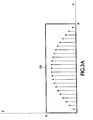
- Shown in Figure 5 is the spatial relationship between an electric field and media in a rectangular waveguide that could be used in an embodiment of the drying apparatus.
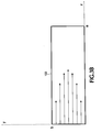
- Shown in Figure 6 is a spatial relationship between an electric field and media in a rectangular waveguide that could be used in an embodiment of the drying apparatus.
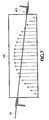
- Shown in Figure 7 is a spatial relationship between an electric field and media in a rectangular waveguide that could be used in an embodiment of the drying apparatus.
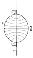
- Shown in Figure 8 is a spatial relationship between an electric field and media in a circular waveguide that could be used in an embodiment of the drying apparatus.
- the drying apparatus is not limited to the disclosed embodiments. Although an embodiment of the drying apparatus will be disclosed in the context of an inkjet imaging device, such as an inkjet printer, it should be recognized that embodiments of the drying apparatus could be used in a variety of applications in which it is desired to selectively dry a fluid while reducing heating of the material upon which the fluid is placed.
- FIG. 1 Shown in Figure 1 is a simplified schematic diagram of an embodiment of an inkjet imaging device, inkjet printer 10, including a simplified representation of an embodiment of the drying apparatus, radiation heater 12.
- Controller 14 receives image data corresponding to an image and generates print data used by print head driver 16 included within controller 14. It should be recognized that, alternatively, inkjet printer 10 could be implemented with printhead driver 16 located externally to controller 14. Typically, the image data is supplied by a computer.
- Print head driver 16 generates drive signals that cause print head 18 to eject ink onto media 20 in a way that forms an image corresponding to the image data.
- the ink may include compounds added to increase its dielectric loss.
- Print head 18 includes an array of nozzles from which ink droplets are ejected.
- Print head 18 includes reservoirs for storing the different colors of ink (such as cyan, magenta, yellow, and black) used to form the images on media 20.
- media 20 After passing beneath print head 18, media 20 passes through radiation heater 12 during which water is removed from the ink by exposure to the electromagnetic energy generated by radiation heater 12. Radiation heater 12 exposes media 20 to the electromagnetic energy it generates so that the ink absorbs significantly more power than media 20. As a result, water is removed from the ink deposited on media 20 without significant heating of media 20, thereby reducing the amount of shrinking experienced by media 20. In addition, because radiation heater 12 is positioned close to print head 18 and downstream print head 18 in the media path, water is removed from the ink sufficiently rapidly to significantly reduce the amount of water absorbed into media 20, thereby reducing distortion of media 20 that would result from water absorption. However, depending upon the rate at which media 20 is moved, print head 18 maybe positioned farther or more closely to print head 18.
- the cutoff frequency for the TE 20 mode is at a higher frequency than the cutoff frequency for the TE 10 mode.
- the axial electric field component is zero and the transverse electric field component has only a component corresponding to the y axes.
- the spatial variation of the transverse electric field in the z dimension (the axial direction in rectangular waveguide 100) is determined by the propagation constant ⁇ .
- the value of ⁇ can, in general, be complex , including an imaginary component and a real component.
- the real component of ⁇ is dependent upon the mode propagating within rectangular waveguide 100 and the permittivity and permeability of the dielectric (typically air) within rectangular waveguide 100.
- the real component of ⁇ accounts for the shift in the phase of the electric field dependent upon the position along the z axis within rectangular waveguide 100.
- the imaginary component is dependent upon resistive loss in the walls of rectangular waveguide 100 (usually relatively small) or energy absorption by a load, such as ink and media, placed within rectangular waveguide 100.
- the imaginary component of ⁇ corresponds to the attenuation constant for the magnitude of the electric field along the z axis within rectangular waveguide 100 where the loading occurs.
- the axial electric field component is zero and the transverse electric field component has only a component corresponding to the x axes.
- the spatial variation of the transverse electric field is given by equation 5.
- FIG. 3a and Figure 3b Shown in Figure 3a and Figure 3b are graphical representations of the electric field magnitude across rectangular waveguide 100 for the TE 10 mode and the TE 01 mode.
- the magnitude of the transverse electric field follows the magnitude of a half cycle of a sinusoid across either the x axes or the y axes.
- the electric field rectangular waveguide 100 will go through a single maximum near the center and be substantially zero near the sidewalls of rectangular waveguide 100.
- the previously discussed expressions for the transverse electric field apply to a rectangular waveguide for which there is only electromagnetic energy propagating in one direction.
- a standing wave will result.
- the distribution of the electric field for a cross section in the x-y plane would be the same. However, the maximum amplitude of the electric field will vary along the z axes and this would be taken into consideration to position media 20 for the drying operation.
- Shown in Figure 4 is a simplified schematic representation of an embodiment of the drying apparatus, including radiation heater 200.
- Radiation heater 200 generates electromagnetic energy that propagates through ink deposited on media 20. Most of the power dissipated in the ink results from exposure of the ink to the electric field. The heating of ink on media 20 results primarily from the action of the time varying electric field upon the dipoles within the ink.
- the orientation of the electric fields generated by radiation heater 200 relative to a longitudinal axes of fibers within media 20 contributes to the preferential dissipation of power emitted from radiation heater 200 in the ink deposited on the surface of media 20 instead of media 20.
- radiation heater 200 By using radiation heater 200, the increase in temperature experienced by media 20 during drying of the ink is lower than would result had convection or conduction heaters been used. As a result of the lower temperatures to which media 20 is exposed, shrinking of media 20 is reduced. Using resistive convection or conduction heaters to dry ink can cause shrinking of media 20 resulting from the power dissipated in the media. The shrinking can be sufficient to cause the print job to be discarded. Using the typical types of microwave heaters can also cause unacceptable amounts of warping in media 20 resulting from the absorption of microwave energy into media 20.
- radiation heater 200 has the capability to supply sufficient power to rapidly dry ink on the surface of media 20 while keeping the power dissipated within media 20 at a relatively low level, the water included within the ink is less likely to be absorbed into the fibers of media 20 and shrinking resulting from heating of media 20 is less likely to result. Absorption of water into media 20 can cause a warping of media 20 known as cockle. The severity of cockle can be sufficient to cause discarding of the print job.
- Radiation heater 200 includes rectangular waveguide 202 and a power source, such as electromagnetic energy source 204.
- Electromagnetic energy source 204 generates the electromagnetic radiation that propagates down rectangular waveguide 202.
- Electromagnetic energy source 204 could include for example, a magnetron tube to generate high frequency electromagnetic radiation.
- the radiation generated by electromagnetic energy source 204 is coupled into rectangular waveguide 202.
- the coupling of the electromagnetic radiation into rectangular waveguide 202 may be done so that either the TE 10 or the TE 01 mode of propagation results (with the frequency of the output from electromagnetic energy source 204 above the cutoff frequency of the desired mode) by proper placement of an output probe from electromagnetic energy source 204 within rectangular waveguide 202.
- the TE 10 mode is excited.
- the TE 01 mode is excited.
- media 20 is formed so that the longitudinal axes of the fibers within it are parallel to the longest dimension (perpendicular to the shortest dimension) of media 20. However, some sizes of media 20 are formed so that the longitudinal axes of the fibers are perpendicular to the longest dimension (parallel to the shortest dimension) of media 20.
- the orientation of the longitudinal axes of the fibers within media 20 with respect to its longest and shortest dimensions is generally determined by how large rolls of media 20 are cut after their formation.
- the fibers within media 20 contain water molecules. Upon exposure to a time varying electric field, the power dissipated within media 20 results primarily from the movement of polarized water molecules contained within the fibers of media 20.
- the amount of power absorbed by media 20 will be maximized when the electric field vector is substantially parallel to the orientation of the longitudinal axes of the fibers in media 20.
- the amount of power absorbed into media 20 changes from a maximum to a minimum.
- the power absorbed by the ink placed upon media 20 does not have the orientation dependence that exists for media 20.
- media 20 moves through rectangular waveguide 202 through slot 206, with slot 206 placed on the face of rectangular waveguide 202 corresponding to the largest cross sectional dimension.
- rectangular waveguide 202 is terminated by a load matched to its characteristic impedance so that there is a forward propagating wave down rectangular waveguide 202, but the amplitude of any reflected wave is substantially zero.
- the placement of the output probe from electromagnetic energy source 204 is such that the TE 10 mode is excited within rectangular waveguide 202. With the establishment of the TE 10 mode, the resulting electric field will exist substantially parallel to the direction of movement of media 20 through slot 206.
- this unit of media 20 is moved through rectangular waveguide 202 so that the longitudinal axes of the fibers are substantially perpendicular to the electric field, then the power absorbed within media 20 will be at a relative minimum with respect to the absorption of power as a function of the spatial orientation between the electric field and the longitudinal axes of the fibers.
- the unit of media 20 can be moved through rectangular waveguide 202 so that the longitudinal axes of the fibers is substantially perpendicular to the electric field vector.
- One way to reduce the power dissipated in a unit of media 20 is to control the orientation of the longitudinal axes of fibers within units of media 20 with respect to the direction of movement of media 20 through slot 206.
- consistently ensuring that the orientation of the longitudinal axes of the fibers on all units of media 20 passed through slot 206 is substantially perpendicular to the electric field may be difficult because of variation of the fiber orientation between units of media 20.
- Another way in which to establish a substantially perpendicular relationship between the longitudinal axes of fibers within units of media 20 and the electric field is to orient the electric field so that it is perpendicular to a plane formed by a unit of media 20 moving through slot 206.
- it will exist substantially perpendicular to the longitudinal axes of fibers within units of media 20 independent of the orientation of the longitudinal axes of the fibers within units of media 20 or the orientation of units of media 20 as they move through rectangular waveguide 202.
- Establishing the TE 01 mode within rectangular waveguide 202 will creates this relationship between the electric field and the longitudinal axes of the fibers.
- the power absorbed by units of media 20 will be at a relative minimum.
- the wall currents on the largest area face flow in a direction parallel to the electric field (the vertical direction in Figure 4).
- Placing Slot 206 in the axial direction on the largest area face of rectangular waveguide 202 would (without use of additional measures) disrupt the flow of the wall currents on the largest area face of rectangular waveguide 202 and interfere with the establishment of the TE 01 mode.
- Shown in Figure 5 is a more detailed representation of rectangular waveguide 202.
- waveguide choke 208 is attached at slot 206.
- waveguide choke 208 substantially reduces the amount of energy that would otherwise be radiated from slot 206, providing for more efficient operation of embodiments of the drying apparatus.
- waveguide choke 208 uses a magnetron operating at 2.45 giga-hertz in a WR340 size rectangular waveguide.
- the slots are shown in Figure 5 as located at the midpoint of their respective walls, the position of the slots could be moved toward either of the other walls in rectangular waveguide 202.
- TM 11 mode there are propagation modes (for example, the TM 11 mode in a rectangular waveguide) for which the wall currents flow in the axial direction of the rectangular waveguide.
- a slot can be placed in a wall in the axial direction to allow media to be moved through the slot so that the electric field exists substantially perpendicular to a plane defined by the media while moving through the rectangular waveguide.
- a waveguide choke would not need to be used because the disruption to the wall currents resulting from a slot in a wall in the axial direction is sufficiently small to permit propagation of the TM 11 mode.
- waveguide choke 208 is matched to the wavelength of the TE 01 mode propagating within rectangular waveguide 202.
- Waveguide choke 208 shown in Figure 5, is not necessarily in proper relative proportion to rectangular waveguide 202.
- Member 210 and member 212 (as well as the corresponding members on the opposite of rectangular waveguide 202 ) are each a quarter wavelength long. The short at the end of member 210 establishes a wall current maximum at this end of member 210. A quarter wavelength away from the short (at the intersection of member 210 and member 212) the wall currents are at zero. A quarter wavelength away from the intersection of member 210 and member 212 (at the intersection of member 212 with the face of rectangular waveguide 202) the wall currents are again at a maximum.
- the effect waveguide choke 208 is to reduce disruption of the wall currents at slot 206, thereby permitting the TE 01 mode to propagate within rectangular waveguide 202.
- FIG. 6 shows an implementation of rectangular waveguide 300 for which slot 302 has been placed on the smallest area face of rectangular waveguide 300.
- Waveguide choke 208 permits slot 302 to be placed in the axial direction on the smallest area face of rectangular waveguide 300 without substantial disruption of the wall currents.
- the TE 10 mode establishes a electric field substantially perpendicular to the fibers of media 20.
- Figure 6 shows slot 302 located in the center of the face of rectangular waveguide 300, it should be recognized the slot 302 could be located near the top or bottom of the face. With slot 302 located near the top or bottom of the face, there may be less disruption of wall currents, thereby permitting the TE 10 mode to be more easily established as the dominant propagation mode.
- rectangular waveguide 202 and rectangular waveguide 300 could be modified to include an internal ridge on the top sidewall and an internal ridge on the bottom sidewall along the axial direction, centered at the midpoint along the cross section, respectively, of the top sidewall and the bottom sidewall. Where the ridges are located within the cross section of the rectangular waveguide, the distance between the top sidewall interior surface and the bottom sidewall interior surface is reduced. These ridges have an effect similar to the plates of a parallel plate capacitor to increase the uniformity and intensity of the electric field between the ridges within rectangular waveguide 202 and rectangular waveguide 300, thereby compensating for attenuation of the electric field magnitude resulting from power absorption by the ink and media.
- Non-perpendicularity between the electric field and the longitudinal axes of the fibers can be controlled by changing the direction of media movement through the rectangular waveguide, the orientation of the media with respect to the direction of media movement through the rectangular waveguide, changing the orientation of the rectangular waveguide with respect to the direction of media movement through the rectangular waveguide, or some combination of two or more of these factors.
- non-perpendicularity between the electric field and the longitudinal axes of the fibers can be controlled as shown in Figure 7 by locating slot 400 and slot 402 on opposite faces of rectangular waveguide 404 so that the plane in which media 20 moves through rectangular waveguide 404 is tilted with respect to the planes established by the two faces of the rectangular waveguide perpendicular to the electric field.
- slot 400 and slot 402 could be placed on the two faces of rectangular waveguide perpendicular to the electric field to achieve a different range of non-perpendicularity between the electric field and the longitudinal axes of the fibers.
- the degree of non-perpendicularity for which a problem will result from the absorption of power in the media will vary depending upon environmental conditions (such as temperature and humidity) and media types. Determination of the maximum permissible degree of non-perpendicularity so that the shrinkage of the media remains within an acceptable range can be done empirically for the expected range of media types and environmental conditions.
- a first way in which the maximum acceptable degree of non-perpendicularity could be determined would use the configuration shown in Figure 4, with slot 206 made sufficiently long to permit media 20 to move through slot 206 while rotated at any angle up to 90 degrees.
- the electric field will exist substantially parallel to the direction of movement of media 20 through slot 206.
- the long axes of media 20 will be substantially parallel to the direction of movement of media 20 through slot 206.
- measurements of the media temperature change and forward power before and after the location of media 20 are made for a variety of angles between the long dimension of media 20 and the direction of movement of media 20 through slot 206.
- Measurement of the temperature of media 20 could be accomplished by using a thermal imaging camera. Then, by understanding the relationship between the amount of shrinking and the temperature media 20 reaches from the absorption of power, a maximum acceptable degree of non-perpendicularity can be determined.
- the maximum acceptable degree of non-perpendicularity is associated with a media temperature and a corresponding amount of shrinking and will vary depending upon the environmental conditions and the type of media for which the determination is made.
- a second way in which the maximum acceptable degree of non-perpendicularity could be determined involves the measurement of the power propagated through rectangular waveguide 202 on the load side of media 20 while it is positioned within slot 206.
- a TE 10 mode is established within rectangular waveguide 202.
- the power propagated on the load side of media 20 is measured as the angle between the electric field and the longitudinal axes of the fibers within media 20 is changed. With the orientation between the electric field and the longitudinal axes of the fibers within media 20 incrementally changing from substantially parallel to substantially perpendicular, the incremental increase in power propagated down rectangular waveguide 202 toward load 200 results from a reduction in the power absorbed by media 20.
- the minimum amount of power absorbed by media 20 can be measured.
- the maximum allowable non-perpendicularity between the electric field and the fibers can be determined.
- Circular waveguide 500 Shown in Figure 8 is an example of a circular waveguide 500 that could be used for an embodiment of the drying apparatus.
- Circular waveguide 500 is operating in the TE 11 mode.
- the axial electric field is zero and the transverse electric has field lines as shown in Figure 8.
- the electric field lines are substantially perpendicular to the plane defined by media 20. It should be recognized that slot 502 and slot 504 could be move around the circumference of circular waveguide without establishing a degree of non-perpendicularity between the longitudinal axes of the fibers in media 20 and the electric field.
Landscapes
- Physics & Mathematics (AREA)
- Electromagnetism (AREA)
- Health & Medical Sciences (AREA)
- General Health & Medical Sciences (AREA)
- Toxicology (AREA)
- Constitution Of High-Frequency Heating (AREA)
- Drying Of Solid Materials (AREA)
- Ink Jet (AREA)
- Accessory Devices And Overall Control Thereof (AREA)
Applications Claiming Priority (2)
| Application Number | Priority Date | Filing Date | Title |
|---|---|---|---|
| US09/846,147 US6428161B1 (en) | 2001-04-30 | 2001-04-30 | Drying apparatus |
| US846147 | 2001-04-30 |
Publications (2)
| Publication Number | Publication Date |
|---|---|
| EP1261237A1 true EP1261237A1 (de) | 2002-11-27 |
| EP1261237B1 EP1261237B1 (de) | 2007-06-27 |
Family
ID=25297077
Family Applications (1)
| Application Number | Title | Priority Date | Filing Date |
|---|---|---|---|
| EP02252754A Expired - Lifetime EP1261237B1 (de) | 2001-04-30 | 2002-04-18 | Trocknungsvorrichtung |
Country Status (4)
| Country | Link |
|---|---|
| US (1) | US6428161B1 (de) |
| EP (1) | EP1261237B1 (de) |
| JP (1) | JP3642764B2 (de) |
| DE (1) | DE60220854T2 (de) |
Families Citing this family (14)
| Publication number | Priority date | Publication date | Assignee | Title |
|---|---|---|---|---|
| JP2005193615A (ja) * | 2004-01-09 | 2005-07-21 | Oki Data Corp | 画像形成装置 |
| US7298994B2 (en) * | 2004-04-16 | 2007-11-20 | Eastman Kodak Company | Process and printing machine for the use of liquid print colors |
| JP4943088B2 (ja) * | 2006-08-11 | 2012-05-30 | 美濃窯業株式会社 | 連続焼成装置 |
| JP4943087B2 (ja) * | 2006-08-11 | 2012-05-30 | 大学共同利用機関法人自然科学研究機構 | 連続焼成炉及び連続焼成方法 |
| US20080282573A1 (en) * | 2007-05-14 | 2008-11-20 | William Hein | Tilting microwave dryer and heater |
| JP5460976B2 (ja) | 2008-06-25 | 2014-04-02 | 株式会社ミマキエンジニアリング | インクジェットプリンタ |
| JP2010005915A (ja) | 2008-06-26 | 2010-01-14 | Mimaki Engineering Co Ltd | インクジェットプリンタ及び印刷方法 |
| JP2010012752A (ja) | 2008-07-07 | 2010-01-21 | Mimaki Engineering Co Ltd | インクジェットプリンタ及び印刷方法 |
| CN101939168B (zh) | 2008-10-07 | 2012-12-05 | 株式会社御牧工程 | 喷墨打印机 |
| JP4891978B2 (ja) | 2008-11-28 | 2012-03-07 | 株式会社ミマキエンジニアリング | インクジェットプリンタ |
| JP5631057B2 (ja) * | 2010-05-17 | 2014-11-26 | キヤノン株式会社 | インクジェット記録装置および校正方法 |
| CN102569967B (zh) * | 2012-01-04 | 2015-02-11 | 西安电子科技大学 | 波导调配器中抑制电磁场泄露的方法 |
| JP6486169B2 (ja) * | 2015-03-31 | 2019-03-20 | 帝人株式会社 | 加熱方法、炭素繊維の製造方法及び炭素繊維並びに加熱装置 |
| JP2018122561A (ja) * | 2017-02-03 | 2018-08-09 | 株式会社Screenホールディングス | 画像記録装置、乾燥装置および画像記録方法 |
Citations (5)
| Publication number | Priority date | Publication date | Assignee | Title |
|---|---|---|---|---|
| US3740515A (en) * | 1970-11-27 | 1973-06-19 | Canadian Patents Dev | Microwave heating apparatus |
| US4626640A (en) * | 1984-10-02 | 1986-12-02 | U.S. Philips Corporation | Microwave arrangement for heating material |
| US5278375A (en) * | 1990-03-07 | 1994-01-11 | Microondes Energie Systemes | Microwave applicator device for the treatment of sheet or lap products |
| US5631685A (en) * | 1993-11-30 | 1997-05-20 | Xerox Corporation | Apparatus and method for drying ink deposited by ink jet printing |
| WO2000004746A1 (en) * | 1998-07-16 | 2000-01-27 | The Board Of Regents, The University Of Texas System | Method and apparatus for rapid drying of coated materials with close capture of vapors |
Family Cites Families (12)
| Publication number | Priority date | Publication date | Assignee | Title |
|---|---|---|---|---|
| DE2515823C2 (de) | 1975-04-11 | 1984-06-07 | Felix Schoeller jr. GmbH & Co KG, 4500 Osnabrück | Verfahren zur Herstellung eines durch Mikrowellenbehandlung zu trocknenden fotografischen Trägermaterials |
| JP2629170B2 (ja) * | 1985-06-08 | 1997-07-09 | ブラザー工業株式会社 | レーザプリンタ |
| US5264869A (en) * | 1991-08-19 | 1993-11-23 | Xerox Corporation | Electro-optical control apparatus and system for spot position control in an optical output device |
| US5563644A (en) | 1992-02-03 | 1996-10-08 | Xerox Corporation | Ink jet printing processes with microwave drying |
| US5220346A (en) * | 1992-02-03 | 1993-06-15 | Xerox Corporation | Printing processes with microwave drying |
| US5500668A (en) | 1994-02-15 | 1996-03-19 | Xerox Corporation | Recording sheets for printing processes using microwave drying |
| US5693129A (en) | 1997-01-13 | 1997-12-02 | Xerox Corporation | Ink jet ink compositions comprising anti-curl hydroxyamide derivatives and printing processes |
| US5814138A (en) | 1997-01-24 | 1998-09-29 | Xerox Corporation | Microwave dryable thermal ink jet inks |
| US6090749A (en) | 1997-03-31 | 2000-07-18 | Hewlett-Packard Company | Method for applying clear, vivid, and water-fast printed images to a susbtrate |
| JPH10315456A (ja) | 1997-05-12 | 1998-12-02 | Xerox Corp | プリント装置及びインクジェットプリンタ |
| US5997623A (en) | 1997-06-16 | 1999-12-07 | Xerox Corporation | Ink jet inks comprising anti-curl agents and printing processes |
| US5853469A (en) | 1997-07-31 | 1998-12-29 | Xerox Corporation | Ink compositions for ink jet printing |
-
2001
- 2001-04-30 US US09/846,147 patent/US6428161B1/en not_active Expired - Fee Related
-
2002
- 2002-04-18 EP EP02252754A patent/EP1261237B1/de not_active Expired - Lifetime
- 2002-04-18 DE DE60220854T patent/DE60220854T2/de not_active Expired - Fee Related
- 2002-04-19 JP JP2002117036A patent/JP3642764B2/ja not_active Expired - Fee Related
Patent Citations (5)
| Publication number | Priority date | Publication date | Assignee | Title |
|---|---|---|---|---|
| US3740515A (en) * | 1970-11-27 | 1973-06-19 | Canadian Patents Dev | Microwave heating apparatus |
| US4626640A (en) * | 1984-10-02 | 1986-12-02 | U.S. Philips Corporation | Microwave arrangement for heating material |
| US5278375A (en) * | 1990-03-07 | 1994-01-11 | Microondes Energie Systemes | Microwave applicator device for the treatment of sheet or lap products |
| US5631685A (en) * | 1993-11-30 | 1997-05-20 | Xerox Corporation | Apparatus and method for drying ink deposited by ink jet printing |
| WO2000004746A1 (en) * | 1998-07-16 | 2000-01-27 | The Board Of Regents, The University Of Texas System | Method and apparatus for rapid drying of coated materials with close capture of vapors |
Also Published As
| Publication number | Publication date |
|---|---|
| JP2003022890A (ja) | 2003-01-24 |
| DE60220854T2 (de) | 2008-03-06 |
| US6428161B1 (en) | 2002-08-06 |
| DE60220854D1 (de) | 2007-08-09 |
| JP3642764B2 (ja) | 2005-04-27 |
| EP1261237B1 (de) | 2007-06-27 |
Similar Documents
| Publication | Publication Date | Title |
|---|---|---|
| US6428161B1 (en) | Drying apparatus | |
| US5631685A (en) | Apparatus and method for drying ink deposited by ink jet printing | |
| US6901683B2 (en) | Method and apparatus for electromagnetic drying of printed media | |
| US7137694B2 (en) | Ink drying system for printer | |
| US10308010B2 (en) | Infrared-heated air knives for dryers | |
| US5410283A (en) | Phase shifter for fine tuning a microwave applicator | |
| EP2899030B1 (de) | Strahlungswärmeregelung mit einstellbarem reflektierendem Element | |
| CA1094144A (en) | Device for fusing and fixing a toner image on a carrier | |
| JP2018166035A (ja) | マイクロ波加熱装置および画像記録装置 | |
| US10744807B2 (en) | Microwave dryers for printing systems that utilize electromagnetic and radiative heating | |
| EP3461230B1 (de) | Drosseln für mikrowellentrockner, die mikrowellenenergie blockieren und das trocknen erleichtern. | |
| JP5934624B2 (ja) | 乾燥装置、乾燥装置を備えた印刷装置、および乾燥方法 | |
| US6072167A (en) | Enhanced uniformity in a length independent microwave applicator | |
| EP1283780A2 (de) | System und verfahren zum trocknen von druckfarbe mittels mikrowellenenergie | |
| JP2008179107A (ja) | プリンタ、印刷方法 | |
| JPS5826979A (ja) | マイクロ波による加熱及び乾燥装置 | |
| JPS629686A (ja) | ガスレ−ザ−装置 | |
| JP7454701B2 (ja) | 被照射材料を乾燥させるための方法、及び当該方法を実行するための赤外線照射装置 | |
| US10980087B2 (en) | Microwave coupler with integrated microwave shield | |
| US10052887B1 (en) | Serpentine microwave dryers for printing systems | |
| US8136935B2 (en) | Inkjet printer and ink dryer | |
| WO2018173395A1 (ja) | 印刷装置および印刷方法 | |
| US20250306507A1 (en) | Fixing device and recording medium floating device | |
| JP4134473B2 (ja) | 高周波加熱装置 | |
| JP2008183844A (ja) | プリンタ、印刷方法 |
Legal Events
| Date | Code | Title | Description |
|---|---|---|---|
| PUAI | Public reference made under article 153(3) epc to a published international application that has entered the european phase |
Free format text: ORIGINAL CODE: 0009012 |
|
| AK | Designated contracting states |
Kind code of ref document: A1 Designated state(s): AT BE CH CY DE DK ES FI FR GB GR IE IT LI LU MC NL PT SE TR |
|
| AX | Request for extension of the european patent |
Free format text: AL;LT;LV;MK;RO;SI |
|
| 17P | Request for examination filed |
Effective date: 20030204 |
|
| AKX | Designation fees paid |
Designated state(s): DE FR GB |
|
| 17Q | First examination report despatched |
Effective date: 20050610 |
|
| GRAP | Despatch of communication of intention to grant a patent |
Free format text: ORIGINAL CODE: EPIDOSNIGR1 |
|
| GRAS | Grant fee paid |
Free format text: ORIGINAL CODE: EPIDOSNIGR3 |
|
| GRAA | (expected) grant |
Free format text: ORIGINAL CODE: 0009210 |
|
| AK | Designated contracting states |
Kind code of ref document: B1 Designated state(s): DE FR GB |
|
| REG | Reference to a national code |
Ref country code: GB Ref legal event code: FG4D |
|
| REF | Corresponds to: |
Ref document number: 60220854 Country of ref document: DE Date of ref document: 20070809 Kind code of ref document: P |
|
| EN | Fr: translation not filed | ||
| PLBE | No opposition filed within time limit |
Free format text: ORIGINAL CODE: 0009261 |
|
| STAA | Information on the status of an ep patent application or granted ep patent |
Free format text: STATUS: NO OPPOSITION FILED WITHIN TIME LIMIT |
|
| 26N | No opposition filed |
Effective date: 20080328 |
|
| PG25 | Lapsed in a contracting state [announced via postgrant information from national office to epo] |
Ref country code: FR Free format text: LAPSE BECAUSE OF FAILURE TO SUBMIT A TRANSLATION OF THE DESCRIPTION OR TO PAY THE FEE WITHIN THE PRESCRIBED TIME-LIMIT Effective date: 20080222 |
|
| PGFP | Annual fee paid to national office [announced via postgrant information from national office to epo] |
Ref country code: DE Payment date: 20080602 Year of fee payment: 7 |
|
| PG25 | Lapsed in a contracting state [announced via postgrant information from national office to epo] |
Ref country code: DE Free format text: LAPSE BECAUSE OF NON-PAYMENT OF DUE FEES Effective date: 20091103 |
|
| REG | Reference to a national code |
Ref country code: GB Ref legal event code: 732E Free format text: REGISTERED BETWEEN 20120329 AND 20120404 |
|
| PGFP | Annual fee paid to national office [announced via postgrant information from national office to epo] |
Ref country code: GB Payment date: 20130326 Year of fee payment: 12 |
|
| GBPC | Gb: european patent ceased through non-payment of renewal fee |
Effective date: 20140418 |
|
| PG25 | Lapsed in a contracting state [announced via postgrant information from national office to epo] |
Ref country code: GB Free format text: LAPSE BECAUSE OF NON-PAYMENT OF DUE FEES Effective date: 20140418 |