EP1261159A1 - Sytème optique différentiel a multiplexage par reparition en longueur d'onde dense - Google Patents
Sytème optique différentiel a multiplexage par reparition en longueur d'onde dense Download PDFInfo
- Publication number
- EP1261159A1 EP1261159A1 EP01310123A EP01310123A EP1261159A1 EP 1261159 A1 EP1261159 A1 EP 1261159A1 EP 01310123 A EP01310123 A EP 01310123A EP 01310123 A EP01310123 A EP 01310123A EP 1261159 A1 EP1261159 A1 EP 1261159A1
- Authority
- EP
- European Patent Office
- Prior art keywords
- optical
- signals
- channels
- signal
- information
- Prior art date
- Legal status (The legal status is an assumption and is not a legal conclusion. Google has not performed a legal analysis and makes no representation as to the accuracy of the status listed.)
- Withdrawn
Links
Images


Classifications
-
- H—ELECTRICITY
- H04—ELECTRIC COMMUNICATION TECHNIQUE
- H04J—MULTIPLEX COMMUNICATION
- H04J14/00—Optical multiplex systems
- H04J14/02—Wavelength-division multiplex systems
-
- H—ELECTRICITY
- H04—ELECTRIC COMMUNICATION TECHNIQUE
- H04B—TRANSMISSION
- H04B10/00—Transmission systems employing electromagnetic waves other than radio-waves, e.g. infrared, visible or ultraviolet light, or employing corpuscular radiation, e.g. quantum communication
- H04B10/50—Transmitters
- H04B10/501—Structural aspects
- H04B10/506—Multiwavelength transmitters
Definitions
- This invention relates generally to communications and, more particularly, to optical communications systems.
- a DWDM signal is created by multiplexing several sequences (or streams) of information bits, e.g., M streams, on M different optical wavelengths (or channels).
- a DWDM signal may be created by modulating each laser of an M laser array with an associated one of the M information streams and combining the M laser array output signals, where each laser produces light at a different wavelength.
- each stream of information is conveyed via a separate optical channel (i.e., by an optical signal having a particular wavelength).
- M information-bearing signals are processed for providing an optical wavelength division multiplexed signal having (N) (M) channels such that each information bearing signal is associated with a different N channels, where N is greater than or equal to two.
- the apparatus receives the M information-bearing signals and (a) creates M optical signals, each at a different wavelength, by converting each of the M information bearing signals into the optical domain via M of the 2M electrical-to-optical converts, and (b) creates M inverted optical signals, each at a different wavelength, by first inverting each of the M information bearing signals (via the M inverters) before conversion into the optical domain via the remaining M electrical-to-optical converters.
- the M optical signals along with the M inverted optical signals are then applied to the multiplexer, which provides an optical wavelength division multiplexed (WDM) signal having 2M channels.
- WDM optical wavelength division multiplexed
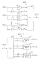
- FIG. 1 A portion of an illustrative apparatus, 100, in accordance with the principles of the invention is shown in FIG. 1.
- mux 115 is a dense wavelength division multiplexer
- electrical-optical element 110-1 is an electrical to optical converter, as known in the art.
- node refers to any communications equipment, illustrations of which are routers, gateways, etc.
- Apparatus 100 comprises M inverters (105-1 through 105-M), 2M electrical-to-optical (E/O) converters (110-1 through 110-2M) and a multiplexer (mux) 115.
- E/O converter provides an optical signal at a different one of 2M wavelengths.
- Each inverter simply inverts the electrical signal applied thereto.
- Apparatus 100 receives M information-bearing signals (in electrical form) as represented by signal 1 through signal M. (It should be noted that the location of the sources for these signals is irrelevant to the inventive concept. For example, some, or all, of these signals could be generated within apparatus 100, or by another element, which may, or may not, be part of a network (both not shown in FIG. 1).
- each signal illustratively represents a pulse-amplitude modulated (PAM) signal wherein predefined voltage levels represents either a binary digit (bit) having a ONE value or a ZERO value.
- PAM pulse-amplitude modulated
- Apparatus 100 performs the following functions: (a) creates M optical signals, (b) creates M inverted optical signals, and (c) multiplexes the M optical signal and the M inverted optical signals to provide a multiplexed optical signal comprising 2M channels for transmission over fiber link 116.
- Signal 1 is applied to E/O 110-1 and inverter 105-1.
- apparatus 100 provides for the synthesis of what is referred to herein as a differential WDM signal.
- every pair of channels carry opposite bits.
- both channels L1 and L2 convey information relating to the same signal (here signal 1) - the non-inverted signal conveyed via channel L1 and the inverted signal conveyed via channel L2.
- the two channels (or wavelengths) carrying information relating to the same signal are referred to as a wavelength pair, or channel pair.
- a ONE is represented by the presence of light during a bit time on an optical channel (i.e., light above a predefined intensity level) while a ZERO is represented by the lack of light during a bit time on the optical channel (light below a predefined intensity level).
- a corresponding receiver uses the difference in light intensity between the optical signals conveyed on each channel pair each bit time for decoding the received signal. In other words, the receiver decodes the received signal by detecting which channel of the channel pair carries a higher intensity light signal - hence the terminology differential WDM. Consequently, there is no need for the receiver to use a fixed threshold detector for detecting ONEs and ZEROES.
- An optical transmission system may also be affected by, what is known in the art as, Inter-Symbol Interference (ISI).
- ISI Inter-Symbol Interference
- a ONE is followed by a ZERO (assuming that a ONE value is represented by the presence of light having intensity above a predefined level, the signal associated with the ONE may not have completely faded away when the corresponding receiver begins the detection process for the ZERO.
- the above-described differential WDM further reduces the affect of ISI.
- the receiver (described below) now uses the difference in light intensity between a channel pair for detecting the presence of a ONE or a ZERO.
- a dark symbol e.g., a ZERO
- a light symbol e.g., a ONE
- WDM receiver 200 comprises demultiplexer (demux) 215, and M differential detectors 210-1 through 210-M).
- Demux 215 receives a WDM signal comprising 2M optical channels from fiber link 116 and provides 2M optical signals on channels L1, L2, L3, L4 ... L(2M-1) and L (2M).
- the 2M optical channels are processed in groups of two, or pairs, by a corresponding one of the differential detectors. For example, channels L1 and L2 are processed by differential detector 210-1.
- each differential detector performs - in effect - differential demodulation since, as noted above, the differential detector makes a decision as to a received bit value being ONE or a ZERO by using the difference in light intensity between a channel pair. For example, each differential detector a priori associates one channel of the channel pair with a ONE, the other with a ZERO. By comparing which channel has more light intensity a ZERO or ONE is selected. Each differential detector provides a sink signal, which is a PAM electrical representation of the information stream (i.e., each differential detector also provides for a conversion from the optical domain to the electrical domain).
- WDM receiver 200 provides M output signals as represented by signals sink 1 through sink M.
- present WDM receivers typically utilize a fixed threshold per wavelength. As such, one is more at the mercy of channel impairments and signal degradation. For example, as the signal level falls due to increased fiber length, it is more likely to make errors due to a lower margin against the threshold. Also, since different wavelengths might suffer with different degrees of channel impairments, threshold adjustments are required per wavelength and in some cases are not straight forward. However, in accordance with the invention, and as described above, in a differential mode there is no need for fixed thresholds since the differential detector detects which channel, of the channel pair, is stronger. As a result of this fact, the relative signal strength between the wavelength pair remains more intact.
- the inventive concept allows an optical signal to travel farther for a given level of degradation. Consequently, the inventive concept provides for better detection at a lower signal strengths - thus, providing the ability to transmit farther with the same signal strength when compared to present systems.
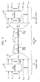
- FIGs. 3 - 5 A portion of an illustrative communications system, 300, in accordance with the principles of the invention is shown in FIG. 3.
- mux 310 is a dense wavelength division multiplexer
- de-mux 320 is a dense wavelength division demultiplexer, as known in art.
- mux 310 is a dense wavelength division multiplexer
- de-mux 320 is a dense wavelength division demultiplexer, as known in art.
- some or all of these elements may be implemented using stored-program-control processors, memory, and/or appropriate interface cards (not shown).
- Portion 300 comprises a source node A and a destination node (or sink node) B coupled via fiber link 350.
- the latter comprises fiber spans (e.g. optical fiber cabling) and a representative repeater 315 (i.e., there may be more than one).
- a repeater is not required for the inventive concept and is shown in FIG. 3 merely for completeness.
- Source node A receives M optical signals as represented by L 1 , L 2 , ... L M . Each optical signal conveys a different information stream at a different wavelength.
- WDM wavelength division multiplexed
- optical WDM signal 311 N is viewed as comprising M groups of optical signals, each group comprising N channels.
- Optical WDM signal 311 N transits fiber link 350, which via repeater 315 - amplifies/regenerates the signal (as represented by optical WDM signal 311 ').
- Fiber link 350 provides optical WDM signal 311 ' to destination node B. The latter performs a complementary function to source node A to recover the original optical WDM signal comprising M channels.
- the received optical WDM signal, 311 ' is demultiplexed into (N)(M) separate channels via demultiplexer (demux) 320. These (N)(M) separate channels are applied to M decoders 325 in M groups of N channels.
- M decoders 325 decodes the information from each of the N groups back into a corresponding one of the M channels as represented by output optical signals L 1 ', L 2 ', ... L M '.
- output optical signals L 1 ', L 2 ', ... L M ' are represented by output optical signals L 1 ', L 2 ', ... L M '.
- destination node B would further include a multiplexer (not shown) to form the optical WDM signal comprising M channels either as part of M decoders 325 or a separate element.
- the multiple encoders for encoding each of the received M optical signals onto N different channels could all be different, or the same, or combinations thereof.
- FIG. 4 Another illustrative embodiment is shown in FIG. 4, which is similar to FIG. 3, showing source node A coupled to destination B via fiber link 450.
- the elements shown in FIG. 4 are well known and will not be described in detail. For simplicity, similar components between FIGs. 3 and 4 are not described again, e.g., fiber link 350 and fiber link 450.
- source node A comprises optical-to-electrical converters 405, electrical-to-optical converters 455, inverters 465, electrical-to-optical converters 465 and multiplexer (mux) 410.
- Apparatus 400 receives M optical signals (each conveying information via the use of intensity modulation), which are applied to optical-to-electrical converters 405, which convert the M optical signals into the electrical domain.
- the electrical form of each of the M signals is applied to (a) inverters 465, which inverts each of the M signals, and (b) optical-to electrical converters 455 for conversion back into the optical domain, (obviously, the conversion from the optical domain to the electrical domain and back again for the M signals along this path could be eliminated entirely).
- Inverters 465 provides M inverted signals to electrical-to-optical converters 465, which provides M inverted forms of the M optical signals (M inverted optical signals).
- Mux 410 multiplexes the M optical signals and the M inverted optical signals to provide optical WDM signal 4 11 N , which comprises 2M channels, for transmission on fiber link 450.
- de-mux 420 receives optical WDM signal 411 ' N (after amplification/regeneration, if any) and provides M pairs of optical signals to differential detectors 480, which provide M optical signals.
- a system can be designed with some wavelengths not using the above-described operation.
- M signals are processed in accordance with the inventive concept to create (N)(M) optical channels and K signals are not processed in accordance with the invention.
- K of the signals are processed in a conventional manner, while M of the signals (L 1 through L M ) are processed in accordance with the invention.
- inventive concept was described in the context of multiplexers and demultiplexers, the inventive concept is also applicable to other types of filtering devices, optical or otherwise, such as, but not limited to, optical add/drop multiplexers, etc.
Applications Claiming Priority (2)
| Application Number | Priority Date | Filing Date | Title |
|---|---|---|---|
| US681720 | 1996-07-29 | ||
| US09/681,720 US7072592B2 (en) | 2001-05-25 | 2001-05-25 | Differential dense wavelength division multiplexing (DDWDM) in optical systems |
Publications (1)
| Publication Number | Publication Date |
|---|---|
| EP1261159A1 true EP1261159A1 (fr) | 2002-11-27 |
Family
ID=24736487
Family Applications (1)
| Application Number | Title | Priority Date | Filing Date |
|---|---|---|---|
| EP01310123A Withdrawn EP1261159A1 (fr) | 2001-05-25 | 2001-12-04 | Sytème optique différentiel a multiplexage par reparition en longueur d'onde dense |
Country Status (4)
| Country | Link |
|---|---|
| US (1) | US7072592B2 (fr) |
| EP (1) | EP1261159A1 (fr) |
| JP (1) | JP4388730B2 (fr) |
| CA (1) | CA2380121C (fr) |
Cited By (2)
| Publication number | Priority date | Publication date | Assignee | Title |
|---|---|---|---|---|
| WO2005050884A1 (fr) | 2003-11-20 | 2005-06-02 | Nippon Telegraph And Telephone Corporation | Systeme de transmission multiplexee de longueurs d'ondes |
| WO2020038867A1 (fr) * | 2018-08-23 | 2020-02-27 | Eaton Intelligent Power Limited | Convertisseur de média et procédé de fonctionnement d'un convertisseur de média |
Families Citing this family (8)
| Publication number | Priority date | Publication date | Assignee | Title |
|---|---|---|---|---|
| US7272327B2 (en) * | 2003-04-29 | 2007-09-18 | Nortel Networks Limited | Multi-detector detection of optical signals |
| JP5130702B2 (ja) * | 2006-12-05 | 2013-01-30 | 富士通株式会社 | 偏波直交制御装置 |
| US8009988B2 (en) * | 2007-11-20 | 2011-08-30 | Phillips Mary R | Raman cancellation and management in CATV transport and distribution via RF spectrum inversion |
| RU2606106C2 (ru) | 2011-08-03 | 2017-01-10 | Алькон Рисерч, Лтд. | Гибкий глазной хирургический зонд |
| US8718466B2 (en) | 2012-07-12 | 2014-05-06 | Micron Technology Inc. | Method and apparatus providing wave division multiplexing optical communication system with active carrier hopping |
| US9319005B2 (en) * | 2012-07-13 | 2016-04-19 | Rf Micro Devices, Inc. | Multi-band/multi-mode power amplifier with signal path hardware sharing |
| EP3116144A4 (fr) * | 2014-03-07 | 2017-11-08 | Nec Corporation | Appareil de transmission optique, appareil de communication optique, système de communication optique, et procédé de communication optique |
| CN114665969A (zh) * | 2020-12-23 | 2022-06-24 | 华为技术有限公司 | 信号发送装置、信号接收装置、方法、光传输系统 |
Citations (3)
| Publication number | Priority date | Publication date | Assignee | Title |
|---|---|---|---|---|
| FR2537364A1 (fr) * | 1982-12-01 | 1984-06-08 | Instruments Sa | Procede de transmission d'informations par fibre optique et dispositif pour la mise en oeuvre du procede |
| FR2563672A1 (fr) * | 1984-04-26 | 1985-10-31 | Lignes Telegraph Telephon | Systeme de transmission d'informations numeriques sur fibre optique |
| EP0449474A2 (fr) * | 1990-03-26 | 1991-10-02 | AT&T Corp. | Liaison de données optique couplée en courant continu utilisant la transmission différentielle |
Family Cites Families (1)
| Publication number | Priority date | Publication date | Assignee | Title |
|---|---|---|---|---|
| US5257124A (en) * | 1991-08-15 | 1993-10-26 | General Instrument Corporation | Low distortion laser system for AM fiber optic communication |
-
2001
- 2001-05-25 US US09/681,720 patent/US7072592B2/en not_active Expired - Fee Related
- 2001-12-04 EP EP01310123A patent/EP1261159A1/fr not_active Withdrawn
-
2002
- 2002-04-04 CA CA002380121A patent/CA2380121C/fr not_active Expired - Fee Related
- 2002-05-22 JP JP2002147975A patent/JP4388730B2/ja not_active Expired - Lifetime
Patent Citations (3)
| Publication number | Priority date | Publication date | Assignee | Title |
|---|---|---|---|---|
| FR2537364A1 (fr) * | 1982-12-01 | 1984-06-08 | Instruments Sa | Procede de transmission d'informations par fibre optique et dispositif pour la mise en oeuvre du procede |
| FR2563672A1 (fr) * | 1984-04-26 | 1985-10-31 | Lignes Telegraph Telephon | Systeme de transmission d'informations numeriques sur fibre optique |
| EP0449474A2 (fr) * | 1990-03-26 | 1991-10-02 | AT&T Corp. | Liaison de données optique couplée en courant continu utilisant la transmission différentielle |
Cited By (6)
| Publication number | Priority date | Publication date | Assignee | Title |
|---|---|---|---|---|
| WO2005050884A1 (fr) | 2003-11-20 | 2005-06-02 | Nippon Telegraph And Telephone Corporation | Systeme de transmission multiplexee de longueurs d'ondes |
| EP1686714A1 (fr) * | 2003-11-20 | 2006-08-02 | Nippon Telegraph and Telephone Corporation | Systeme de transmission multiplexee de longueurs d'ondes |
| EP1686714A4 (fr) * | 2003-11-20 | 2010-08-18 | Nippon Telegraph & Telephone | Systeme de transmission multiplexee de longueurs d'ondes |
| CN1745530B (zh) * | 2003-11-20 | 2012-10-03 | 日本电信电话株式会社 | 波分复用传送系统 |
| WO2020038867A1 (fr) * | 2018-08-23 | 2020-02-27 | Eaton Intelligent Power Limited | Convertisseur de média et procédé de fonctionnement d'un convertisseur de média |
| US11146336B2 (en) | 2018-08-23 | 2021-10-12 | Eaton Intelligent Power Limited | Media converter and method for operating a media converter |
Also Published As
| Publication number | Publication date |
|---|---|
| JP2003060623A (ja) | 2003-02-28 |
| JP4388730B2 (ja) | 2009-12-24 |
| CA2380121C (fr) | 2008-07-08 |
| US20020176132A1 (en) | 2002-11-28 |
| US7072592B2 (en) | 2006-07-04 |
| CA2380121A1 (fr) | 2002-11-25 |
Similar Documents
| Publication | Publication Date | Title |
|---|---|---|
| US6366373B1 (en) | Method of intrinsic continuous management data transmission in fiber optic communications | |
| CN101213775B (zh) | Dpsk调制-解调方法及使用该方法的光通信设备和系统 | |
| JP4767676B2 (ja) | 光受信装置 | |
| US7630636B1 (en) | Optical swapping of digitally-encoded optical labels | |
| US7076177B1 (en) | Bit-rate independent optical receiver and method thereof | |
| EP2830239B1 (fr) | Procédé, système et dispositif émetteur-récepteur pour signaux optiques numériques à transmission bidirectionnelle via une liaison de transmission optique | |
| US6820230B2 (en) | Self synchronous scrambler apparatus and method for use in dense wavelength division multiplexing | |
| CA2380121C (fr) | Multiplexage differentiel dense en longueur d'onde (ddwdm) dans des systemes optiques | |
| US4791407A (en) | Alternate mark/space inversion line code | |
| US8019222B2 (en) | Digital encoding of labels for optical packet networks | |
| US20030223761A1 (en) | Embedded operational channel network management | |
| EP1318639B1 (fr) | Un système de transmission numérique avec un récepteur utilisant des circuits de décision parallèles | |
| US6580538B1 (en) | Reduction of optical impairments in wavelength division multiplexed systems employing a wavelength bus architecture | |
| US20020126349A1 (en) | Multiplexing information on multiple wavelengths in optical systems | |
| US6486985B1 (en) | Method for transmitting an additional data signal and a useful data signal in an optical network | |
| KR100458648B1 (ko) | 광 채널의 삽입 및 추출의 운용기능을 갖는 광 트랜스폰더 | |
| US11973537B2 (en) | Flexible rate passive optical network incorporating use of delay modulation | |
| JP2000151505A (ja) | 光送受信装置 | |
| US8502711B2 (en) | Swap tolerant coding and decoding circuits and methods | |
| US7433603B2 (en) | Using active and passive optical components for an optical network | |
| JP4000372B2 (ja) | 光csk変調を用いる光cdma通信システム | |
| US20040052533A1 (en) | System and method for noise suppression in optical communication | |
| KR20010016959A (ko) | 광 cdma방식의 광 스위칭 장치 | |
| JPS6377227A (ja) | ブロツク符号光伝送方式 |
Legal Events
| Date | Code | Title | Description |
|---|---|---|---|
| PUAI | Public reference made under article 153(3) epc to a published international application that has entered the european phase |
Free format text: ORIGINAL CODE: 0009012 |
|
| 17P | Request for examination filed |
Effective date: 20011212 |
|
| AK | Designated contracting states |
Kind code of ref document: A1 Designated state(s): AT BE CH CY DE DK ES FI FR GB GR IE IT LI LU MC NL PT SE TR |
|
| AX | Request for extension of the european patent |
Free format text: AL;LT;LV;MK;RO;SI |
|
| 17Q | First examination report despatched |
Effective date: 20030411 |
|
| AKX | Designation fees paid |
Designated state(s): DE FR GB |
|
| 17Q | First examination report despatched |
Effective date: 20030411 |
|
| APBN | Date of receipt of notice of appeal recorded |
Free format text: ORIGINAL CODE: EPIDOSNNOA2E |
|
| APBR | Date of receipt of statement of grounds of appeal recorded |
Free format text: ORIGINAL CODE: EPIDOSNNOA3E |
|
| APAF | Appeal reference modified |
Free format text: ORIGINAL CODE: EPIDOSCREFNE |
|
| RAP3 | Party data changed (applicant data changed or rights of an application transferred) |
Owner name: LUCENT TECHNOLOGIES INC. |
|
| APBT | Appeal procedure closed |
Free format text: ORIGINAL CODE: EPIDOSNNOA9E |
|
| STAA | Information on the status of an ep patent application or granted ep patent |
Free format text: STATUS: THE APPLICATION HAS BEEN WITHDRAWN |
|
| 18W | Application withdrawn |
Effective date: 20110627 |