EP1260784B1 - A combined self-defense device - Google Patents
A combined self-defense device Download PDFInfo
- Publication number
- EP1260784B1 EP1260784B1 EP02011133A EP02011133A EP1260784B1 EP 1260784 B1 EP1260784 B1 EP 1260784B1 EP 02011133 A EP02011133 A EP 02011133A EP 02011133 A EP02011133 A EP 02011133A EP 1260784 B1 EP1260784 B1 EP 1260784B1
- Authority
- EP
- European Patent Office
- Prior art keywords
- spray
- light
- defense device
- flange
- nozzle body
- Prior art date
- Legal status (The legal status is an assumption and is not a legal conclusion. Google has not performed a legal analysis and makes no representation as to the accuracy of the status listed.)
- Expired - Lifetime
Links
Images

Classifications
-
- F—MECHANICAL ENGINEERING; LIGHTING; HEATING; WEAPONS; BLASTING
- F41—WEAPONS
- F41H—ARMOUR; ARMOURED TURRETS; ARMOURED OR ARMED VEHICLES; MEANS OF ATTACK OR DEFENCE, e.g. CAMOUFLAGE, IN GENERAL
- F41H9/00—Equipment for attack or defence by spreading flame, gas or smoke or leurres; Chemical warfare equipment
- F41H9/10—Hand-held or body-worn self-defence devices using repellant gases or chemicals
Definitions
- the invention relates to a manually operated self-defense device comprising in combination a defending spray portion and a light portion. Both means may be used in combination in self-defense actions where the flashlight of the light portion should help the intended victim to allocate the attacker's face and/or to partially blind and deter him and subsequently or at the same time the defending spray can be applied against the attacker's yes if the attacker continues in his action against the victim.
- the U.S. pat. No. 5 405 134 discloses a handle with a spray device attached to a baton, where the baton is in the form of a lamp.
- a defending spray is located in a transversal part of the handle. Due to its relatively big size and mass this device is designed for a law-enforcement personnel rather than for individuals carrying such device for an occasional an rare use in a handbag or pocket.
- the U.S. pat. No. 5 086 377 discloses a baton i.e. a defending device consisting of a middle portion comprising a defending spray and an end portions with a light and sound alarm devices. This device is also big in size and therefore not suitable to be carried in a handbag or pocket.
- a pistol-shape device that includes in a housing a storage battery, two lamps emitting blue and white light respectively, a sound source and a chemical repellent container.
- the device includes at least three separate compartments, internal wiring and piping to provide the respective connections between the operating switches, battery, lamps and a gas nozzle.
- the device is operated by two switches and a trigger what may be rather confusing in the situation when it should be used against an unexpected attackers and therefore very quickly and with an immediate and surprising effect.
- due to its considerable size such device is not suitable to be carried in a handbag specifically in a ladies shoulder bag or a clutch bag or a pocket.
- the U.S. pat. No. 5 941 629 discloses a lamp-shape device with a defending gas compartment on one end and a battery and light portion on the other end.
- the elongated form extends substantially over the palm of the user and in operation the handle must be turned at an angle of 90 ° or 180 ° if the gas spray is to be applied after the previous using the lamp.
- the gas actuator and the electrical switch are situated on the opposite sides of the lamp what may cause certain problems if the device is to be used quickly and with immediate effect against attackers.
- Utility model DE 81 30 809 U teaches a multi-functional housing comprising several chambers, which are designed to receive a spray-container, batteries, light source, keys and coins.
- the light switch is actuated by a slide on the top of the housing while the spray valve by a push button situated on the side wall of the housing.
- this solution represents a typical spacious and weighty aggregate device performing several independent functions based on a conventional arrangement and with a rather complicated controlling system.
- Another object of the present invention is to provide a self-defense device that is easy to handle in operation and where the both functions, i.e. the flashlight and the gas spray function may be initiated by one hand and/or one finger.
- the self-defense device according to the invention may be easily adapted to the shape of a conventional gas container and to other commercially available parts thus making it susceptible of low costs of manufacture and low sale price.
- the invention relates to the combined self-defense device having a spray portion consisting of a spray container with a front wall, a side wall a bottom and a spray outlet means for actuating a spray release valve associated with a nozzle and a light portion connected to said spray portion consisting of a light housing to receive a battery and a light source for emitting a light beam substantially in the direction of the nozzle with a switch on the outside of the light housing for connecting the battery to the light source.
- the devices comprises a flange with an upper end and a lower end and an opening for the spray outlet means and fixed with its lower end on the upper wall of the spray container, a nozzle body having an actuating surface on its top end and mounted for longitudinal motion in the flange and including a conduit adapted to receive the spray outlet means and a nozzle connected to the conduit and directed outwards the nozzle body.
- a light emitting diode is used what permits due to its extremely small size to attach the light portion to any part of the spray portion including the side wall the bottom of the container or the flange without substantially extending over the conventional shape of the container.
- the device may be operated by one finger so that both the light and the gas valve may be actuated practically simultaneously or in a step by step procedure. In the latter case the light is first actuated by smoothly pressing the switch and then by subsequent additional depressing the switch the spray gas valve is actuated to release the spray from the nozzle.
- the switch may be actuated with one finger, for example by the forefinger and the spray gas valve by the thumb, both independently.
- the light portion may be removed and used independently as a small pocket lamp.
- the lower end of the flange extends at least partially over the side wall of the spray container. This enables to provide a suitable shape of the whole device for example a uniform cylindrical or prismatic form or to bring the form of the container portion in conformity with the commercial miniature light source.
- the first embodiment of the combined self-defense device according to the present invention is shown in Fig. 1 and Fig. 2 .
- the device consists of a spray portion and a light portion.
- the spray portion includes a spray container 1 having a bottom 12 a side wall and a front wall 11.
- the container 1 is filled in with a repellent irritating gas such as a tear gas or pepper spray etc.
- the container further comprises a gas outlet tube 13 movable within the front wall 11 and adapted to actuate a valve located inside the container 1 to control the on/off function of the spray container 1.
- This arrangement represents a conventional part of the most commercially available gas containers and therefore the valve is not shown in the drawings.
- a flange 2 mounted on the front wall 11 provided with an opening 21 for the outlet tube 13 and with an inner sliding surface 22 provided in its upper part in which a nozzle body 3 is mounted for longitudinal motion.
- the nozzle body 3 has a conduit 31 for receiving the outlet tube 13 of the spray container 1 and connected to a nozzle 32 directed substantially perpendicular to the longitudinal axis of the self-defending device.
- the top of the nozzle body 3 serves as a actuating surface 33 of the spray container 1.
- the outlet tube 13 may be alternatively attached to the conduit 31 of the nozzle body 3 to perform the same function of actuating the valve inside the container 1. Both alternatives are further also defined as spray outlet means.
- a light housing 4 is secured to the nozzle body 3 engaging by its lower wall the actuating surface 33 of the nozzle body 3.
- the actuating surface 34 of the nozzle body 3 has a recess 34 that matches with a shoulder 43 performed on the lower wall of the light housing 4 .
- the light housing 4 is preferably in the shape of a disc or a low truncated cone and has an internal cavity in which a battery 41, a switch 43 and the associated contacts and wiring are located.
- the switch 43 comprises a resilient contact plate 45 disposed on the upper surface of the light housing 4.
- the light housing 4 is further provided with a lateral hole in the form adapted to hold a light source 42.
- the light housing 41 is secured in the nozzle body in such a position that the hole axis and consequently that of the light source beam are substantially parallel to the axis of the nozzle 32.
- the battery is a button-type battery and the light source is a light emitting diode which both are light in weight and occupy a minimum space. This construction enables to attain one of the significant objects of the invention i.e. to provide a small in size, light in weight and comfortable self-defense device.
- the contact plate 45 bends downwards and actuates the switch 43 to render it in the on-position.
- the electric circuit is thereby closed and the light source 42 - a diode is energized by the battery 41 to emit an intensive beam of light capable to at least temporarily blind an assailant.
- An additional pressure on the contact plate 45 causes the light housing 4 to move together with the engaged nozzle body 3 downwards in the flange 2 and to actuate the gas valve in the manner described above so that the gas is sprayed out of the nozzle 32.
- the gas release mechanism of the spray container 1 may be provided by a safety pin or button, which may be also incorporated in the commercially available protective gas containers and therefore is not shown in the drawings. Since the light portion does not constitute an integral part of the nozzle body 3 or the flange 2 the light portion may be removed and used independently as a small pocket lamp.
- the following description is directed to other embodiments of the device according to the invention which however imply common features and therefore the parts of the same function and may be of the same or similar shape and form bear the same reference numerals.
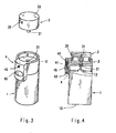
- the second embodiment of the self-defense device according to the invention is shown in Fig. 3 and Fig. 4 .
- the container mechanism and that of the nozzle body 3 mounted in the flange 2 and their functions are analogous to the embodiment shown in Fig. 1 and 2 . Therefore, the following description will be limited to the flange 2 and the light source 4.
- the flange 2 secured to the container 1 as in the previous embodiment is provided by a lateral portion extending out of the cylindrical wall of the flange 2.
- the lateral portion is similar in shape to the light housing 4 as shown in the first embodiment with the exception that in order to ensure the same direction of the light beam emitted by the light source 42 as that of the nozzle the hole for receiving the light source 42 is made in the upper surface of the light housing 4 along with the switch contact plate 45.
- the device of the second embodiment is actuated by two fingers so that the nozzle body 3 is actuated by the thumb and the switch 43 by the index finger. Accordingly, the spray portion may be operated independently of the light portion.
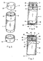
- the light housing 4 may by attached to the spray container 1 by various means including the arrangement shown in Fig. 5 and 6 where the spray container 1 has a shoulder that matches the corresponding recess in the light housing 4.
- the light source 42 is arranged laterally in the light housing 4 so that the light housing 4 may be positioned on the spray container 1 in the manner that the central line of the light beam emitted by the light source 4 is parallel to the axis of the gas nozzle 32.
- the device may be used as a lamp or as a gas spray-defending device or in combination in the order described above.
- the light housing may be removed from the spray container 1 and used as a small pocket lamp.
- the fourth embodiment of the device according to the invention as shown in Fig. 7 comprises an additional feature that is applicable to all previously described designs of the self-defense device.
- the flange 2 is provided by an additional element, a jacket 23.
- the jacket 23 extends downwardly from the lower end of the flange 2 over the whole length of the spray container 1.
- the jacket 23 thus provides a suitable cover for the spray container 1 and may be formed to any shape different from the shape of a commercially available container or adapted to the shape of a commercially available miniature lamps.
- This arrangement also allows that the spray outlet means may be actuated by pressing the container 1 on its bottomside into the jacket 23 towards the flange 2.
Landscapes
- Engineering & Computer Science (AREA)
- General Engineering & Computer Science (AREA)
- Containers And Packaging Bodies Having A Special Means To Remove Contents (AREA)
- Nozzles (AREA)
- Arrangement Of Elements, Cooling, Sealing, Or The Like Of Lighting Devices (AREA)
- Cereal-Derived Products (AREA)
Applications Claiming Priority (2)
| Application Number | Priority Date | Filing Date | Title |
|---|---|---|---|
| CZ20011822A CZ290623B6 (cs) | 2001-05-23 | 2001-05-23 | Kombinované osobní obranné zařízení |
| CZ20011822 | 2001-05-23 |
Publications (3)
| Publication Number | Publication Date |
|---|---|
| EP1260784A2 EP1260784A2 (en) | 2002-11-27 |
| EP1260784A3 EP1260784A3 (en) | 2003-07-02 |
| EP1260784B1 true EP1260784B1 (en) | 2008-08-13 |
Family
ID=5473397
Family Applications (1)
| Application Number | Title | Priority Date | Filing Date |
|---|---|---|---|
| EP02011133A Expired - Lifetime EP1260784B1 (en) | 2001-05-23 | 2002-05-21 | A combined self-defense device |
Country Status (5)
| Country | Link |
|---|---|
| US (1) | US6676270B2 (cs) |
| EP (1) | EP1260784B1 (cs) |
| AT (1) | ATE404842T1 (cs) |
| CZ (1) | CZ290623B6 (cs) |
| DE (1) | DE60228166D1 (cs) |
Families Citing this family (28)
| Publication number | Priority date | Publication date | Assignee | Title |
|---|---|---|---|---|
| CZ20032987A3 (cs) * | 2003-11-04 | 2005-06-15 | Břetislav Ing. Košťál | Světelný adaptér pro kontejner s obranným sprejem |
| CA2453171C (en) * | 2003-11-06 | 2008-01-29 | Dennis Siteman | Improvements in truncheons, protective batons, canes and the like |
| US20060201974A1 (en) * | 2005-03-10 | 2006-09-14 | Sure Shake, Llc | Condiment cartridge |
| USD543657S1 (en) * | 2005-06-30 | 2007-05-29 | Cooper Technologies Company | Lampholder |
| US7614526B2 (en) * | 2005-07-19 | 2009-11-10 | Summit Packaging Systems, Inc | Aerosol can holder |
| US20080049414A1 (en) * | 2006-02-10 | 2008-02-28 | Mckay William D Sr | Stain and odor detection and cleanup system |
| US20070189834A1 (en) * | 2006-02-10 | 2007-08-16 | Thethe Hartz Mountain Corporation | Stain and odor detection and cleanup system |
| WO2008019166A2 (en) * | 2006-02-22 | 2008-02-14 | Tiger Light, Inc. | Personal defense device |
| CZ302415B6 (cs) * | 2007-02-16 | 2011-05-04 | Koštál@Bretislav | Svetelný adaptér |
| USD585520S1 (en) | 2007-07-26 | 2009-01-27 | Michael Teig | Personal defense device |
| US8210395B1 (en) * | 2008-06-06 | 2012-07-03 | Morris Traci L | Spray dispenser and light emitting combination assembly |
| WO2011026199A2 (en) * | 2009-09-07 | 2011-03-10 | Nedzad Niksic | Illuminant spray / atomiser actuator button |
| US8499974B2 (en) * | 2009-12-07 | 2013-08-06 | Ron Bennett | Automatic light switch on a self defense device |
| US8479432B2 (en) | 2010-08-10 | 2013-07-09 | Joel L. Braun | Non-lethal weapon mount system with modular weapon components |
| US9719667B2 (en) * | 2011-02-22 | 2017-08-01 | Custom Molded Products, Llc | Clip for providing light to a spa feature |
| US20120211618A1 (en) * | 2011-02-22 | 2012-08-23 | Custom Molded Products, Inc. | Clip for Providing Light to a WaterJet |
| US8757443B2 (en) * | 2011-09-15 | 2014-06-24 | Gojo Industries, Inc. | Portable dispenser |
| US9737186B2 (en) | 2011-11-11 | 2017-08-22 | Michael DeGeorge | Apparatus and method for detecting materials |
| USD711575S1 (en) * | 2012-01-13 | 2014-08-19 | Quy That Ton | Flashlight |
| JP2016088609A (ja) * | 2014-11-11 | 2016-05-23 | 明秀 東畑 | Ledランプ付きノズルボタン |
| US20170266678A1 (en) * | 2016-03-15 | 2017-09-21 | Fredrick Harrington | Spray bottle with storage |
| US20170320083A1 (en) * | 2016-05-04 | 2017-11-09 | CG&Hayward, LLC | Sprayer nozzle with embedded battery-operated ultraviolet light(s) |
| US20180016088A1 (en) * | 2016-07-15 | 2018-01-18 | The Dial Corporation | Composition container with a lighting device to illuminate a target area |
| US11598517B2 (en) | 2019-12-31 | 2023-03-07 | Lumien Enterprise, Inc. | Electronic module group |
| US12281783B2 (en) | 2019-12-31 | 2025-04-22 | Lumien Enterprise, Inc. | Electronic module group |
| CN110985903B (zh) | 2019-12-31 | 2020-08-14 | 江苏舒适照明有限公司 | 一种灯模组 |
| CN111503556B (zh) * | 2020-04-23 | 2020-11-27 | 江苏舒适照明有限公司 | 一种射灯结构 |
| US12230950B2 (en) | 2021-07-29 | 2025-02-18 | Lumien Enterprise, Inc. | Junction box |
Family Cites Families (17)
| Publication number | Priority date | Publication date | Assignee | Title |
|---|---|---|---|---|
| US3638836A (en) * | 1970-02-04 | 1972-02-01 | Percy Rosenbloom Jr | Combined flashlight and chemical expelling device |
| US4228484A (en) | 1978-12-04 | 1980-10-14 | Johnstone Malcolm D | LED flasher for battery cell-powered lamp |
| DE8130809U1 (de) * | 1981-10-22 | 1987-09-03 | Rüttinger, Armin, 8999 Scheidegg | Behälter mit Sprüheinrichtung |
| US4968034A (en) | 1988-08-29 | 1990-11-06 | Webert Hsieh | Multi-functional electronic self-protection device |
| US5086377A (en) | 1991-05-31 | 1992-02-04 | Bert Roberts | Personal accessory and defense baton |
| US5158356A (en) * | 1992-02-10 | 1992-10-27 | Guthrie Alan V | Ornamental lamp with internal switch |
| US5307249A (en) * | 1992-07-20 | 1994-04-26 | Vanwynsberghe Dennis S | Fluid dispensing flashlight apparatus |
| US5405134A (en) | 1993-07-15 | 1995-04-11 | Wolfram; Robert D. | Gas ejecting handle attachment for batons and flashlights |
| US5373427A (en) * | 1993-09-10 | 1994-12-13 | Mclean; Roderick G. | Dispenser with source of illumination for self-defense spray canister |
| US5386351A (en) * | 1994-02-15 | 1995-01-31 | Blue Tiger Corporation | Convenience flashlight |
| US5549220A (en) * | 1994-09-16 | 1996-08-27 | Whalen; Patrick J. | Non-lethal device for self-defense |
| DE4445987C1 (de) | 1994-12-22 | 1996-03-07 | Adolf Tuscher | Handbetätigbares Abwehr- und Verteidungsgerät |
| US5556003A (en) * | 1995-09-11 | 1996-09-17 | Johnson, Sabates & Johnson Llc | Hand-held personal defense apparatus |
| US5683168A (en) * | 1996-09-11 | 1997-11-04 | Teig; Willard H. | Spray canister light |
| US5795054A (en) * | 1997-03-05 | 1998-08-18 | Phorm Concept & Design, Inc. | Guardlight |
| DE19741516C1 (de) | 1997-09-20 | 1999-04-01 | Adolf Tuscher | Handbetätigbares Abwehrgerät |
| US6052051A (en) * | 1999-02-23 | 2000-04-18 | Whalen; Patrick J. | Multilocation defense device |
-
2001
- 2001-05-23 CZ CZ20011822A patent/CZ290623B6/cs not_active IP Right Cessation
-
2002
- 2002-05-21 DE DE60228166T patent/DE60228166D1/de not_active Expired - Lifetime
- 2002-05-21 AT AT02011133T patent/ATE404842T1/de not_active IP Right Cessation
- 2002-05-21 EP EP02011133A patent/EP1260784B1/en not_active Expired - Lifetime
- 2002-05-22 US US10/156,778 patent/US6676270B2/en not_active Expired - Fee Related
Also Published As
| Publication number | Publication date |
|---|---|
| US20020176254A1 (en) | 2002-11-28 |
| CZ20011822A3 (cs) | 2002-09-11 |
| CZ290623B6 (cs) | 2002-09-11 |
| ATE404842T1 (de) | 2008-08-15 |
| EP1260784A3 (en) | 2003-07-02 |
| EP1260784A2 (en) | 2002-11-27 |
| DE60228166D1 (de) | 2008-09-25 |
| US6676270B2 (en) | 2004-01-13 |
Similar Documents
| Publication | Publication Date | Title |
|---|---|---|
| EP1260784B1 (en) | A combined self-defense device | |
| EP1530019B1 (en) | A control unit for a defence-spray container in combination with a light source | |
| US5893483A (en) | Personal hand-held protection device | |
| US5629679A (en) | Personal security device | |
| US7866841B2 (en) | Compact flashlight | |
| US5673819A (en) | Holder for aerosol defense spray device | |
| US7008076B2 (en) | Folding knife light tool | |
| US5673436A (en) | Defense glove | |
| US8210710B2 (en) | Multi-functional flashlight | |
| US4434914A (en) | Personal defense actuator | |
| US5795054A (en) | Guardlight | |
| USD461555S1 (en) | Safety syringe | |
| US7329021B1 (en) | Lighted remote control with key | |
| US4247844A (en) | Alarm light | |
| US6454426B1 (en) | Miniature flashlight device having housing with outer and inner enclosures | |
| CA2353928A1 (en) | Portable aerosol-type fire-fighting protection device | |
| US5347436A (en) | Combination baton/light emitting device | |
| US7641353B2 (en) | Light attachment | |
| USD458333S1 (en) | Firearm safety switch | |
| US6270234B1 (en) | Portable light | |
| US7334915B2 (en) | Searchlight grip | |
| US5508683A (en) | Weapon handgrip safety alarm | |
| US6749316B1 (en) | Side arm baton with flashlight and camera | |
| US5971750A (en) | Lighter having the function of indicating | |
| US20040115579A1 (en) | Cigarette lighter with alarm |
Legal Events
| Date | Code | Title | Description |
|---|---|---|---|
| PUAI | Public reference made under article 153(3) epc to a published international application that has entered the european phase |
Free format text: ORIGINAL CODE: 0009012 |
|
| AK | Designated contracting states |
Kind code of ref document: A2 Designated state(s): AT BE CH CY DE DK ES FI FR GB GR IE IT LI LU MC NL PT SE TR |
|
| AX | Request for extension of the european patent |
Free format text: AL;LT;LV;MK;RO;SI |
|
| PUAL | Search report despatched |
Free format text: ORIGINAL CODE: 0009013 |
|
| AK | Designated contracting states |
Designated state(s): AT BE CH CY DE DK ES FI FR GB GR IE IT LI LU MC NL PT SE TR |
|
| AX | Request for extension of the european patent |
Extension state: AL LT LV MK RO SI |
|
| 17P | Request for examination filed |
Effective date: 20040102 |
|
| AKX | Designation fees paid |
Designated state(s): AT BE CH CY DE DK ES FI FR GB GR IE IT LI LU MC NL PT SE TR |
|
| 17Q | First examination report despatched |
Effective date: 20050614 |
|
| 17Q | First examination report despatched |
Effective date: 20050614 |
|
| GRAP | Despatch of communication of intention to grant a patent |
Free format text: ORIGINAL CODE: EPIDOSNIGR1 |
|
| GRAS | Grant fee paid |
Free format text: ORIGINAL CODE: EPIDOSNIGR3 |
|
| GRAA | (expected) grant |
Free format text: ORIGINAL CODE: 0009210 |
|
| AK | Designated contracting states |
Kind code of ref document: B1 Designated state(s): AT BE CH CY DE DK ES FI FR GB GR IE IT LI LU MC NL PT SE TR |
|
| REG | Reference to a national code |
Ref country code: GB Ref legal event code: FG4D |
|
| REG | Reference to a national code |
Ref country code: CH Ref legal event code: EP |
|
| REG | Reference to a national code |
Ref country code: IE Ref legal event code: FG4D |
|
| REF | Corresponds to: |
Ref document number: 60228166 Country of ref document: DE Date of ref document: 20080925 Kind code of ref document: P |
|
| PG25 | Lapsed in a contracting state [announced via postgrant information from national office to epo] |
Ref country code: ES Free format text: LAPSE BECAUSE OF FAILURE TO SUBMIT A TRANSLATION OF THE DESCRIPTION OR TO PAY THE FEE WITHIN THE PRESCRIBED TIME-LIMIT Effective date: 20081124 Ref country code: NL Free format text: LAPSE BECAUSE OF FAILURE TO SUBMIT A TRANSLATION OF THE DESCRIPTION OR TO PAY THE FEE WITHIN THE PRESCRIBED TIME-LIMIT Effective date: 20080813 |
|
| PG25 | Lapsed in a contracting state [announced via postgrant information from national office to epo] |
Ref country code: AT Free format text: LAPSE BECAUSE OF FAILURE TO SUBMIT A TRANSLATION OF THE DESCRIPTION OR TO PAY THE FEE WITHIN THE PRESCRIBED TIME-LIMIT Effective date: 20080813 Ref country code: FI Free format text: LAPSE BECAUSE OF FAILURE TO SUBMIT A TRANSLATION OF THE DESCRIPTION OR TO PAY THE FEE WITHIN THE PRESCRIBED TIME-LIMIT Effective date: 20080813 |
|
| PG25 | Lapsed in a contracting state [announced via postgrant information from national office to epo] |
Ref country code: BE Free format text: LAPSE BECAUSE OF FAILURE TO SUBMIT A TRANSLATION OF THE DESCRIPTION OR TO PAY THE FEE WITHIN THE PRESCRIBED TIME-LIMIT Effective date: 20080813 |
|
| PG25 | Lapsed in a contracting state [announced via postgrant information from national office to epo] |
Ref country code: DK Free format text: LAPSE BECAUSE OF FAILURE TO SUBMIT A TRANSLATION OF THE DESCRIPTION OR TO PAY THE FEE WITHIN THE PRESCRIBED TIME-LIMIT Effective date: 20080813 |
|
| PG25 | Lapsed in a contracting state [announced via postgrant information from national office to epo] |
Ref country code: PT Free format text: LAPSE BECAUSE OF FAILURE TO SUBMIT A TRANSLATION OF THE DESCRIPTION OR TO PAY THE FEE WITHIN THE PRESCRIBED TIME-LIMIT Effective date: 20090113 |
|
| PLBE | No opposition filed within time limit |
Free format text: ORIGINAL CODE: 0009261 |
|
| STAA | Information on the status of an ep patent application or granted ep patent |
Free format text: STATUS: NO OPPOSITION FILED WITHIN TIME LIMIT |
|
| 26N | No opposition filed |
Effective date: 20090514 |
|
| PGFP | Annual fee paid to national office [announced via postgrant information from national office to epo] |
Ref country code: TR Payment date: 20090505 Year of fee payment: 8 |
|
| PG25 | Lapsed in a contracting state [announced via postgrant information from national office to epo] |
Ref country code: MC Free format text: LAPSE BECAUSE OF NON-PAYMENT OF DUE FEES Effective date: 20090531 |
|
| REG | Reference to a national code |
Ref country code: CH Ref legal event code: PL |
|
| PG25 | Lapsed in a contracting state [announced via postgrant information from national office to epo] |
Ref country code: LI Free format text: LAPSE BECAUSE OF NON-PAYMENT OF DUE FEES Effective date: 20090531 Ref country code: CH Free format text: LAPSE BECAUSE OF NON-PAYMENT OF DUE FEES Effective date: 20090531 Ref country code: SE Free format text: LAPSE BECAUSE OF FAILURE TO SUBMIT A TRANSLATION OF THE DESCRIPTION OR TO PAY THE FEE WITHIN THE PRESCRIBED TIME-LIMIT Effective date: 20081113 |
|
| REG | Reference to a national code |
Ref country code: IE Ref legal event code: MM4A |
|
| PG25 | Lapsed in a contracting state [announced via postgrant information from national office to epo] |
Ref country code: IE Free format text: LAPSE BECAUSE OF NON-PAYMENT OF DUE FEES Effective date: 20090521 |
|
| PG25 | Lapsed in a contracting state [announced via postgrant information from national office to epo] |
Ref country code: GR Free format text: LAPSE BECAUSE OF FAILURE TO SUBMIT A TRANSLATION OF THE DESCRIPTION OR TO PAY THE FEE WITHIN THE PRESCRIBED TIME-LIMIT Effective date: 20081114 |
|
| PG25 | Lapsed in a contracting state [announced via postgrant information from national office to epo] |
Ref country code: LU Free format text: LAPSE BECAUSE OF NON-PAYMENT OF DUE FEES Effective date: 20090521 |
|
| PG25 | Lapsed in a contracting state [announced via postgrant information from national office to epo] |
Ref country code: CY Free format text: LAPSE BECAUSE OF FAILURE TO SUBMIT A TRANSLATION OF THE DESCRIPTION OR TO PAY THE FEE WITHIN THE PRESCRIBED TIME-LIMIT Effective date: 20080813 |
|
| PG25 | Lapsed in a contracting state [announced via postgrant information from national office to epo] |
Ref country code: TR Free format text: LAPSE BECAUSE OF NON-PAYMENT OF DUE FEES Effective date: 20100521 |
|
| PGFP | Annual fee paid to national office [announced via postgrant information from national office to epo] |
Ref country code: GB Payment date: 20140520 Year of fee payment: 13 |
|
| PGFP | Annual fee paid to national office [announced via postgrant information from national office to epo] |
Ref country code: IT Payment date: 20140507 Year of fee payment: 13 |
|
| GBPC | Gb: european patent ceased through non-payment of renewal fee |
Effective date: 20150521 |
|
| PG25 | Lapsed in a contracting state [announced via postgrant information from national office to epo] |
Ref country code: IT Free format text: LAPSE BECAUSE OF NON-PAYMENT OF DUE FEES Effective date: 20150521 |
|
| PG25 | Lapsed in a contracting state [announced via postgrant information from national office to epo] |
Ref country code: GB Free format text: LAPSE BECAUSE OF NON-PAYMENT OF DUE FEES Effective date: 20150521 |
|
| REG | Reference to a national code |
Ref country code: FR Ref legal event code: PLFP Year of fee payment: 15 |
|
| PGFP | Annual fee paid to national office [announced via postgrant information from national office to epo] |
Ref country code: DE Payment date: 20160516 Year of fee payment: 15 |
|
| PGFP | Annual fee paid to national office [announced via postgrant information from national office to epo] |
Ref country code: FR Payment date: 20160516 Year of fee payment: 15 |
|
| REG | Reference to a national code |
Ref country code: DE Ref legal event code: R119 Ref document number: 60228166 Country of ref document: DE |
|
| REG | Reference to a national code |
Ref country code: FR Ref legal event code: ST Effective date: 20180131 |
|
| PG25 | Lapsed in a contracting state [announced via postgrant information from national office to epo] |
Ref country code: DE Free format text: LAPSE BECAUSE OF NON-PAYMENT OF DUE FEES Effective date: 20171201 |
|
| PG25 | Lapsed in a contracting state [announced via postgrant information from national office to epo] |
Ref country code: FR Free format text: LAPSE BECAUSE OF NON-PAYMENT OF DUE FEES Effective date: 20170531 |