EP1260461A1 - Belt conveyor support element and conveyor comprising same - Google Patents
Belt conveyor support element and conveyor comprising same Download PDFInfo
- Publication number
- EP1260461A1 EP1260461A1 EP02291205A EP02291205A EP1260461A1 EP 1260461 A1 EP1260461 A1 EP 1260461A1 EP 02291205 A EP02291205 A EP 02291205A EP 02291205 A EP02291205 A EP 02291205A EP 1260461 A1 EP1260461 A1 EP 1260461A1
- Authority
- EP
- European Patent Office
- Prior art keywords
- roller
- support
- protective screen
- frame
- conveyor
- Prior art date
- Legal status (The legal status is an assumption and is not a legal conclusion. Google has not performed a legal analysis and makes no representation as to the accuracy of the status listed.)
- Granted
Links
Images

Classifications
-
- B—PERFORMING OPERATIONS; TRANSPORTING
- B65—CONVEYING; PACKING; STORING; HANDLING THIN OR FILAMENTARY MATERIAL
- B65G—TRANSPORT OR STORAGE DEVICES, e.g. CONVEYORS FOR LOADING OR TIPPING, SHOP CONVEYOR SYSTEMS OR PNEUMATIC TUBE CONVEYORS
- B65G39/00—Rollers, e.g. drive rollers, or arrangements thereof incorporated in roller-ways or other types of mechanical conveyors
- B65G39/10—Arrangements of rollers
- B65G39/12—Arrangements of rollers mounted on framework
-
- F—MECHANICAL ENGINEERING; LIGHTING; HEATING; WEAPONS; BLASTING
- F16—ENGINEERING ELEMENTS AND UNITS; GENERAL MEASURES FOR PRODUCING AND MAINTAINING EFFECTIVE FUNCTIONING OF MACHINES OR INSTALLATIONS; THERMAL INSULATION IN GENERAL
- F16P—SAFETY DEVICES IN GENERAL; SAFETY DEVICES FOR PRESSES
- F16P1/00—Safety devices independent of the control and operation of any machine
- F16P1/005—Guards for rolls in calendering or other roll machines, e.g. nip guards, finger guards
Definitions
- the present invention relates to a tape support for a conveyor of the type comprising a frame, at least one roller for supporting the strip, which roller is rotatable relative to the frame and comprises axially, at least at one end, a support pin, the frame comprising at less one support leg for the rotary roller, the leg being provided with a notch for receiving the roller support pin, the support comprising in addition a protective screen carried by the frame and arranged opposite the roller.
- the invention further relates to a belt conveyor comprising such supports.
- belt conveyors In order to transport aggregates or stones on a construction site construction or mining site, it is known to use belt conveyors. These include a set of support rollers on which a conveyor belt rests. This band is closed in a loop and is animated by a movement of movement on itself.
- rollers are generally held, at each of their ends, by support legs, these legs themselves being integral with a frame resting on the ground or on a support frame.
- the protective screens are secured to the legs, for example by screwing.
- connection of the rollers and protective screens to the legs of support is relatively complex, which increases the cost of supports and their assembly time.
- the invention aims to provide a support for tape simple structure conveyor, reducing time and cost assembly.
- the subject of the invention is a support for a strip of conveyor of the aforementioned type, characterized in that said protective screen includes means for confining the pin in the notch.
- the invention further relates to a belt conveyor comprising at minus a support as defined above.
- FIG 1 there is shown a support 10 of a belt conveyor.
- the conveyor comprises a band 12 circulating resting on a set of tape supports arranged along the length of the conveyor.
- Each support 10 comprises a frame 14 adapted to be secured to a chassis not shown.
- Each support further comprises, in the embodiment shown, three rollers 16 rotatably mounted in a same plane with respect to the frame 14.
- the rollers 16 are carried by support legs 18 of the frame.
- the tabs 18 extend at each end of the rollers.
- the rollers 16 have a cylindrical lateral surface 20 of which the axis forms the axis of rotation of the roller.
- the roller has axially, at each end, support pins 22 projecting from the cylindrical surface 20 of the rollers.
- the cylindrical lateral surface of the roller is rotatable with respect to the pins. These can be trained by the ends of a single shaft running right through the roller.
- These trunnions are adapted to be engaged and immobilized, as illustrated on FIG. 2, in notches 24 formed in each of the legs 18.
- the pins For their immobilization in rotation relative to the legs 18, the pins have flats whose spacing is equal to the width of the notch.
- the notches 24 open along the front side wall of the legs 18 in a direction X-X extending generally parallel to the plane advancement of the strip 12 carried on the surface of the roller 16 associated.
- the front side wall is that found towards the front of the conveyor considering the direction of advancement of the carrier brown.
- the support 10 comprises, for each roller 16, a screen of protection 26.
- This screen 26 has a solid wall 28 extending along the length of the associated roller 16.
- means 30 for retaining the wall 28 on the lugs 18.
- the screen 28 further comprises means 32 for confinement of the nipples 22 in the associated notches.
- the screen 28 is formed for example from plastic.
- the wall 28 has come of material, at each of its ends, with fixing wings 34 on the legs 12.
- the wall 28 is connected to one end of each of the wings by a set of elastic strips 36.
- the legs 34 extend perpendicular to the wall 28, that is to say perpendicular to the axis of the associated roller 16.
- each tab 34 has an extension 38 forming a handle for supporting the fingers to remove the protective screen 26.
- the means 32 for confining the associated journal comprise a blade 40 extending parallel to the wing 34 on the side of the wing facing the roller.
- the blade 40 is linked at a first end, to the wall 28 and has a second free adapted to apply against the surface of a journal of the roller.
- the wing 34 and the blade 40 define a receiving groove 42 from the front edge of lug 18 considering the direction of travel of the conveyor.
- a projection 44 is arranged over most of the height of the wing 34 in look of the groove 42, the projection being formed at a distance from the bottom of the groove equal to the width of the tab 18.
- the projection 44 is adapted to ensure mechanical retention of the wing on the associated tab, by elastic engagement of the projection 44 along the rear edge of the tab 18 by considering the direction of advance of the strip.
- the wing 34 has, in its face turned towards the roller, a recess circular 46 for receiving the end of the journal 22 of the roller.
- the tab 40 has, at its end free, a concave profile 50 of shape complementary to the pin 22.
- This surface 50 constitutes a radial bearing surface on the pin 22 in order to press it against the bottom of the notch 24.
- the blade 40 Near its end, the blade 40 has a light 52 adapted to allow elastic deformation of its free end and thus elastically biasing the pin 22.
- the wall 28 of the screen has an upper longitudinal edge 28A and a lower edge 28B.
- the means 30 for retaining the wall 28 are adapted to maintain this, so that the upper edge 28A extends immediately below of the strip 12. The upper edge 28A and the contact edge between the strip and roller 16 then extend substantially along the displacement plane Of the band.
- the retaining means are adapted to maintain the edge 28B lightly supported on the lateral surface 20 of the roller in order to ensure a scraping of it.
- the tape support according to the invention is of a relatively structure simple since the protection screen ensures both protection of the roller and holding the roller on the support legs 12.
- the elastic blade 40 ensures locking and holding under pressure of the pins 22 against the bottom of the notches 24.
- the pressure exerted on the pins is obtained by slight deformation elastic of the ends of the blades 40.
- the screen For the installation of the screen, it is engaged from the side of the roller, while the wings 34 are spaced apart from one another.
- the wings 34 are released so that the projections 44 engage elastically behind the legs 12 thus ensuring a retention in position from screen 26.
- the screen 26 is easily removed by releasing the wings 34 by acting on the handles 38. After removal of the screen 26, the damaged roller can be easily released by moving the pins along the length of the notches 24. The axis of the notches extending parallel to the displacement plane tape, the roll can be removed without the tape having to to be raised. Likewise, the repaired roller, or a new roller may be easily reintroduced without the need to lift the band.
Abstract
Description
La présente invention concerne un support de bande pour un convoyeur du type comportant un bâti, au moins un rouleau pour l'appui de la bande, lequel rouleau est rotatif par rapport au bâti et comporte axialement, au moins à une extrémité, un tourillon de support, le bâti comportant au moins une patte de support du rouleau rotatif, la patte étant munie d'une encoche de réception du tourillon de support du rouleau, le support comportant en outre un écran de protection porté par le bâti et disposé en regard du rouleau.The present invention relates to a tape support for a conveyor of the type comprising a frame, at least one roller for supporting the strip, which roller is rotatable relative to the frame and comprises axially, at least at one end, a support pin, the frame comprising at less one support leg for the rotary roller, the leg being provided with a notch for receiving the roller support pin, the support comprising in addition a protective screen carried by the frame and arranged opposite the roller.
L'invention concerne en outre un convoyeur à bande comportant de tels supports.The invention further relates to a belt conveyor comprising such supports.
Afin de transporter des granulats ou des cailloux sur un chantier de construction ou un site d'exploitation de minerais, il est connu d'utiliser des convoyeurs à bande. Ceux-ci comportent un ensemble de rouleaux de support sur lesquels repose une bande de transport. Cette bande est refermée en boucle et est animée d'un mouvement de déplacement sur elle-même.In order to transport aggregates or stones on a construction site construction or mining site, it is known to use belt conveyors. These include a set of support rollers on which a conveyor belt rests. This band is closed in a loop and is animated by a movement of movement on itself.
Les rouleaux sont généralement tenus, à chacune de leurs extrémités, par des pattes de support, ces pattes étant elles-mêmes solidaires d'un bâti reposant sur le sol ou sur un châssis de support.The rollers are generally held, at each of their ends, by support legs, these legs themselves being integral with a frame resting on the ground or on a support frame.
Par ailleurs, il est connu de disposer un écran de protection le long de chaque rouleau en regard de la face du rouleau tournée vers l'amont du convoyeur. Cet écran de protection est maintenu fixe par rapport au bâti et présente un bord affleurant la surface inférieure de la bande. Cet écran est adapté pour éviter le coincement de corps étrangers entre le rouleau et la bande, ainsi que l'écrasement accidentel d'un membre d'un ouvrier dans l'espace de pincement délimité entre le rouleau et la bande.Furthermore, it is known to have a protective screen along each roller opposite the roller face facing upstream of the conveyor. This protective screen is kept fixed relative to the frame and has an edge flush with the bottom surface of the strip. This screen is suitable for preventing the trapping of foreign bodies between the roller and the tape, as well as the accidental crash of a member of a worker in space pinch between the roller and the strip.
Dans les supports de bande connus, les écrans de protection sont solidarisés aux pattes, par exemple par vissage.In known tape supports, the protective screens are secured to the legs, for example by screwing.
Ainsi, la liaison des rouleaux et des écrans de protection aux pattes de support est relativement complexe, ce qui augmente le coût des supports et leur temps d'assemblage.Thus, the connection of the rollers and protective screens to the legs of support is relatively complex, which increases the cost of supports and their assembly time.
L'invention a pour but de proposer un support pour bande de convoyeur dont la structure est simple, réduisant ainsi le temps et le coût d'assemblage. The invention aims to provide a support for tape simple structure conveyor, reducing time and cost assembly.
A cet effet, l'invention a pour objet un support pour bande de convoyeur du type précité, caractérisé en ce que ledit écran de protection comporte des moyens de confinement du tourillon dans l'encoche.To this end, the subject of the invention is a support for a strip of conveyor of the aforementioned type, characterized in that said protective screen includes means for confining the pin in the notch.
Suivant des modes particuliers de réalisation, le support comporte l'une ou plusieurs des caractéristiques suivantes :
- lesdits moyens de confinement comportent une surface de butée appliquée contre le tourillon et assurant le maintien de celui-ci en appui contre le fond de l'encoche ;
- la surface de butée est délimitée sur un organe déformable élastiquement ;
- ledit écran de protection comporte un évidement de réception de l'extrémité du tourillon de support ;
- l'écran de protection comporte des moyens d'enclenchement élastique adaptés pour solidariser l'écran de protection et la patte ; et
- la surface du rouleau et un bord de l'écran de protection définissent un plan de circulation de la bande, et ladite encoche s'ouvre suivant une direction sensiblement parallèle au plan de circulation de la bande.
- said confinement means comprise an abutment surface applied against the pin and ensuring that it remains in abutment against the bottom of the notch;
- the abutment surface is delimited on an elastically deformable member;
- said protective screen comprises a recess for receiving the end of the support pin;
- the protective screen comprises elastic engagement means adapted to secure the protective screen and the tab; and
- the surface of the roller and an edge of the protective screen define a band circulation plane, and said notch opens in a direction substantially parallel to the band circulation plane.
L'invention a en outre pour objet un convoyeur à bande comportant au moins un support tel que défini ci-dessus.The invention further relates to a belt conveyor comprising at minus a support as defined above.
L'invention sera mieux comprise à la lecture de la description qui va suivre, donnée uniquement à titre d'exemple et faite en se référant aux dessins, sur lesquels :
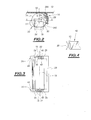
- la figure 1 est une vue en élévation d'un support pour bande de convoyeur selon l'invention ;
- la figure 2 est une vue en coupe transversale du support prise suivant la ligne II-II;
- la figure 3 est une vue de dessus de l'agencement d'un rouleau et de l'écran de protection associé du support de la figure ; et
- la figure 4 est une vue en élévation d'un détail des moyens de confinement d'une extrémité du rouleau prévus sur l'écran de protection.
- Figure 1 is an elevational view of a support for a conveyor belt according to the invention;
- Figure 2 is a cross-sectional view of the support taken along line II-II;
- Figure 3 is a top view of the arrangement of a roller and the associated protective screen of the support of Figure; and
- Figure 4 is an elevational view of a detail of the confinement means of one end of the roller provided on the protective screen.
Sur la figure 1, est représenté un support 10 d'un convoyeur à bande. In Figure 1, there is shown a
Comme connu en soi, le convoyeur comporte une bande 12 circulant
en appui sur un ensemble de supports de bande disposés suivant la longueur
du convoyeur.As known per se, the conveyor comprises a
Chaque support 10 comporte un bâti 14 adapté pour être solidarisé à
un châssis non représenté. Chaque support comporte en outre, dans le
mode de réalisation représenté, trois rouleaux 16 montés rotatifs dans un
même plan par rapport au bâti 14.Each
Les rouleaux 16 sont portés par des pattes de support 18 du bâti. Les
pattes 18 s'étendent à chaque extrémité des rouleaux.The
Les rouleaux 16 présentent une surface latérale cylindrique 20 dont
l'axe forme l'axe de rotation du rouleau. Le rouleau présente axialement , à
chaque extrémité, des tourillons de support 22 faisant saillie par rapport à la
surface cylindrique 20 des rouleaux. La surface latérale cylindrique du rouleau
est rotative par rapport aux tourillons. Ceux-ci peuvent être formés par
les extrémités d'un arbre unique traversant le rouleau de part en part. Ces
tourillons sont adaptés pour être engagés et immobilisés, comme illustré sur
la figure 2, dans des encoches 24 ménagées dans chacune des pattes 18.
Pour leur immobilisation en rotation en rapport aux pattes 18, les tourillons
présentent des méplats dont l'écartement est égal à la largeur de l'encoche.The
Les encoches 24 s'ouvrent suivant la paroi latérale avant des pattes
18 suivant une direction X-X s'étendant généralement parallèlement au plan
d'avancement de la bande 12 portée en appui sur la surface du rouleau 16
associé. La paroi latérale avant est celle trouvée vers l'avant du convoyeur
en considérant le sens d'avancement du brun porteur de la bande.The
En outre, le support 10 comporte, pour chaque rouleau 16, un écran
de protection 26. Cet écran 26 comporte une paroi pleine 28 s'étendant suivant
la longueur du rouleau 16 associé. A chacune des extrémités de la paroi
28 sont prévus des moyens 30 de retenue de la paroi 28 sur les pattes 18.In addition, the
Selon l'invention, l'écran 28 comporte en outre des moyens 32 de
confinement des tétons 22 dans les encoches associées.According to the invention, the
L'écran 28 est formé par exemple en matière plastique.The
Plus précisément, et comme illustré sur la figure 3, la paroi 28 est venue
de matière, à chacune de ses extrémités, avec des ailes 34 de fixation
sur les pattes 12. La paroi 28 est reliée à une extrémité de chacune des ailes
par un ensemble de lamelles élastiques 36.More precisely, and as illustrated in FIG. 3, the
Les pattes 34 s'étendent perpendiculairement à la paroi 28, c'est-à-dire
perpendiculairement à l'axe du rouleau 16 associé.The
La longueur des ailes 24 est supérieure à la largeur des pattes 18, de
sorte qu'à l'opposé de l'extrémité de liaison à la paroi 28, chaque patte 34
présente un prolongement 38 formant une poignée pour l'appui des doigts
afin de démonter l'écran de protection 26.The length of the
Les moyens 32 de confinement du tourillon associé comportent une
lame 40 s'étendant parallèlement à l'aile 34 du côté de l'aile faisant face au
rouleau. La lame 40 est liée à une première extrémité, à la paroi 28 et présente
une seconde libre adaptée pour s'appliquer contre la surface d'un tourillon
du rouleau. L'aile 34 et la lame 40 délimitent une rainure 42 de réception
du bord avant de la patte 18 en considérant le sens d'avancement du
convoyeur.The
Une saillie 44 est disposée sur l'essentiel de la hauteur de l'aile 34 en
regard de la rainure 42, la saillie étant ménagée à une distance du fond de la
rainure égale à la largeur de la patte 18.A
La saillie 44 est adaptée pour assurer une retenue mécanique de l'aile
sur la patte associée, par enclenchement élastique de la saillie 44 le long du
bord arrière de la patte 18 en considérant le sens d'avancement de la bande.The
Enfin, l'aile 34 présente, dans sa face tournée vers le rouleau, un évidement
circulaire 46 de réception de l'extrémité du tourillon 22 du rouleau.Finally, the
La patte 40, telle qu'illustrée sur la figure 4, présente, à son extrémité
libre, un profil concave 50 de forme complémentaire au tourillon 22. Cette
surface 50 constitue une surface d'appui radiale sur le tourillon 22 afin de
presser celui-ci contre le fond de l'encoche 24.The
Au voisinage de son extrémité, la lame 40 présente une lumière 52
adaptée pour permettre une déformation élastique de son extrémité libre et
ainsi solliciter élastiquement le tourillon 22.Near its end, the
La paroi 28 de l'écran présente un bord longitudinal supérieur 28A et
un bord inférieur 28B. The
Les moyens 30 de retenue de la paroi 28 sont adaptés pour maintenir
celle-ci, de sorte que le bord supérieur 28A s'étende immédiatement au-dessous
de la bande 12. Le bord supérieur 28A et l'arête de contact entre la
bande et le rouleau 16 s'étendent alors sensiblement suivant le plan de déplacement
de la bande.The means 30 for retaining the
De même, les moyens de retenue sont adaptés pour maintenir le bord
28B légèrement en appui sur la surface latérale 20 du rouleau afin d'assurer
un raclage de celui-ci.Similarly, the retaining means are adapted to maintain the
Le support pour bande selon l'invention est d'une structure relativement
simple puisque l'écran de protection assure à la fois la protection du
rouleau et le maintien du rouleau sur les pattes de support 12.The tape support according to the invention is of a relatively structure
simple since the protection screen ensures both protection of the
roller and holding the roller on the
En effet, la lame élastique 40 assure un verrouillage et un maintien
sous pression des tourillons 22 contre le fond des encoches 24.Indeed, the
La pression exercée sur les tourillons est obtenue par légère déformation
élastique des extrémités des lames 40.The pressure exerted on the pins is obtained by slight deformation
elastic of the ends of the
Pour la mise en place de l'écran, celui-ci est engagé depuis le côté du
rouleau, alors que les ailes 34 sont écartées élastiquement l'une de l'autre.For the installation of the screen, it is engaged from the side of the
roller, while the
Après mise en place de la paroi 28 et des lames 40 en contact des
tourillons, les logements 46 étant en regard de l'extrémité des tourillons, les
ailes 34 sont relâchées de sorte que les saillies 44 viennent s'enclencher
élastiquement en arrière des pattes 12 assurant ainsi une retenue en position
de l'écran 26.After placing the
En cas de dysfonctionnement d'un rouleau nécessitant son démontage,
l'écran 26 est facilement retiré en dégageant les ailes 34 par action sur
les poignées 38. Après retrait de l'écran 26, le rouleau endommagé peut être
facilement dégagé par déplacement des tourillons suivant la longueur des
encoches 24. L'axe des encoches s'étendant parallèlement au plan de déplacement
de la bande, le rouleau peut être retiré sans que la bande n'ait à
être soulevée. De même, le rouleau réparé, ou un nouveau rouleau peut être
réintroduit facilement sans qu'il soit nécessaire de soulever la bande.In the event of a roller malfunction requiring disassembly,
the
Ainsi, le démontage et le remontage d'un rouleau s'effectuent très facilement.Thus, the disassembly and reassembly of a roll is very easy.
Claims (7)
Applications Claiming Priority (2)
| Application Number | Priority Date | Filing Date | Title |
|---|---|---|---|
| FR0106536 | 2001-05-17 | ||
| FR0106536A FR2824815B1 (en) | 2001-05-17 | 2001-05-17 | CONVEYOR BELT SUPPORT AND CONVEYOR COMPRISING SAME |
Publications (2)
| Publication Number | Publication Date |
|---|---|
| EP1260461A1 true EP1260461A1 (en) | 2002-11-27 |
| EP1260461B1 EP1260461B1 (en) | 2004-04-14 |
Family
ID=8863409
Family Applications (1)
| Application Number | Title | Priority Date | Filing Date |
|---|---|---|---|
| EP02291205A Expired - Lifetime EP1260461B1 (en) | 2001-05-17 | 2002-05-15 | Belt conveyor support element and conveyor comprising same |
Country Status (4)
| Country | Link |
|---|---|
| EP (1) | EP1260461B1 (en) |
| AT (1) | ATE264244T1 (en) |
| DE (1) | DE60200363T2 (en) |
| FR (1) | FR2824815B1 (en) |
Families Citing this family (3)
| Publication number | Priority date | Publication date | Assignee | Title |
|---|---|---|---|---|
| FR2923213B1 (en) * | 2007-11-06 | 2010-04-09 | Rene Brunone | SUPPORT STATION FOR A CONVEYOR BELT WITH DISASSEMBLY OF FACILITATED ROLLERS |
| DE202015105558U1 (en) * | 2015-10-20 | 2017-01-23 | Artur Küpper GmbH & Co. KG | Carrying roller frame with horizontal guide and holding slots |
| DE202015105592U1 (en) * | 2015-10-21 | 2017-01-27 | Artur Küpper GmbH & Co. KG | Carrying frame with swing frame and horizontal guide and holding slots |
Citations (4)
| Publication number | Priority date | Publication date | Assignee | Title |
|---|---|---|---|---|
| GB225969A (en) * | 1923-10-01 | 1924-12-18 | Robert Black | Improvements relating to guards for machine rollers |
| FR2655628A1 (en) * | 1989-12-09 | 1991-06-14 | Mueller Masch Stahlbau Gmbh | DEVICE FOR PROTECTING SCREWS OF CONVEYED BANDS. |
| FR2738230A3 (en) * | 1995-09-02 | 1997-03-07 | Bosch Gmbh Robert | DEVICE FOR RECEIVING AT LEAST ONE TRANSPORT ROLLER |
| FR2782989A1 (en) * | 1998-09-07 | 2000-03-10 | Ibs Services De Bandes Transpo | Guard system for return point of trough conveyor belt consists of four separate and adjustable components fitted with screws |
-
2001
- 2001-05-17 FR FR0106536A patent/FR2824815B1/en not_active Expired - Fee Related
-
2002
- 2002-05-15 AT AT02291205T patent/ATE264244T1/en not_active IP Right Cessation
- 2002-05-15 DE DE60200363T patent/DE60200363T2/en not_active Expired - Fee Related
- 2002-05-15 EP EP02291205A patent/EP1260461B1/en not_active Expired - Lifetime
Patent Citations (4)
| Publication number | Priority date | Publication date | Assignee | Title |
|---|---|---|---|---|
| GB225969A (en) * | 1923-10-01 | 1924-12-18 | Robert Black | Improvements relating to guards for machine rollers |
| FR2655628A1 (en) * | 1989-12-09 | 1991-06-14 | Mueller Masch Stahlbau Gmbh | DEVICE FOR PROTECTING SCREWS OF CONVEYED BANDS. |
| FR2738230A3 (en) * | 1995-09-02 | 1997-03-07 | Bosch Gmbh Robert | DEVICE FOR RECEIVING AT LEAST ONE TRANSPORT ROLLER |
| FR2782989A1 (en) * | 1998-09-07 | 2000-03-10 | Ibs Services De Bandes Transpo | Guard system for return point of trough conveyor belt consists of four separate and adjustable components fitted with screws |
Also Published As
| Publication number | Publication date |
|---|---|
| EP1260461B1 (en) | 2004-04-14 |
| FR2824815A1 (en) | 2002-11-22 |
| DE60200363T2 (en) | 2005-05-12 |
| FR2824815B1 (en) | 2003-08-29 |
| DE60200363D1 (en) | 2004-05-19 |
| ATE264244T1 (en) | 2004-04-15 |
Similar Documents
| Publication | Publication Date | Title |
|---|---|---|
| BE1004897A3 (en) | Closure device, or separation of coverage. | |
| EP2122102B1 (en) | Device with a flexible shutter | |
| EP0256926B1 (en) | Accumulation conveyor | |
| FR2900139A1 (en) | SUPPORT STATION FOR A BAND CONVEYOR AND CONVEYOR HAVING THE SAME | |
| WO2010004233A1 (en) | Tightening device with collar | |
| WO2016124728A1 (en) | Disk brake comprising at least one spring for the elastic return of a brake pad, elastic return spring, and replacement kit | |
| EP3932833B1 (en) | Support station, conveyor belt and method for manufacturing such a support station | |
| EP1260461B1 (en) | Belt conveyor support element and conveyor comprising same | |
| EP0468841B1 (en) | Belt conveyor | |
| EP1564166A1 (en) | Support for a roll of a belt conveyor | |
| EP2058249A1 (en) | Support station for a conveyor belt with demounting of rollers enabled | |
| FR2771080A1 (en) | Motorized endless conveyor belt | |
| FR2460690A1 (en) | SKI BRAKE | |
| FR2928143A1 (en) | CONVEYOR EQUIPPED WITH SUPPORTS FOR THE ASSEMBLY OF ELEMENTS SUCH AS A LOAD GUIDE RAIL | |
| EP1059415B1 (en) | Belt winder, shutter or blind actuation mechanism comprising such a winder and method of its manufacture | |
| EP1644607B1 (en) | Folding door and shutter guide device | |
| EP0156736A1 (en) | Profiled sealing joint, particularly for sealing sliding vehicle doors | |
| EP2158375A2 (en) | Automatic safety lock for roller shutters and roller shutter provided with one such lock | |
| FR2581372A1 (en) | BELT EXTENSIONER | |
| CA2404223A1 (en) | Improved device for automatic centring on belt conveyors | |
| EP0670408B1 (en) | Deflector for the lower transom of a door frame, window frame or similar | |
| FR2975678A1 (en) | Satellite conveyer for gravity conveying system to transport load to location, has cleat comprising stop forming unit to prevent rotation of arm from drive position according to direction opposite to activation direction | |
| FR2853218A1 (en) | WINDOW ASSEMBLY COMPRISING A ROD | |
| FR2928142A1 (en) | Driven roller conveyor for loads, has rollers mounted by end parts, in grooves such that each roller rests only by its cylindrical wall on strand supported by supporting unit i.e. wing, where end parts is formed of cylindrical pilot points | |
| EP2199235B1 (en) | Support station for a conveyor belt |
Legal Events
| Date | Code | Title | Description |
|---|---|---|---|
| PUAI | Public reference made under article 153(3) epc to a published international application that has entered the european phase |
Free format text: ORIGINAL CODE: 0009012 |
|
| AK | Designated contracting states |
Kind code of ref document: A1 Designated state(s): AT BE CH CY DE DK ES FI FR GB GR IE IT LI LU MC NL PT SE TR |
|
| AX | Request for extension of the european patent |
Free format text: AL;LT;LV;MK;RO;SI |
|
| 17P | Request for examination filed |
Effective date: 20030116 |
|
| GRAH | Despatch of communication of intention to grant a patent |
Free format text: ORIGINAL CODE: EPIDOS IGRA |
|
| AKX | Designation fees paid |
Designated state(s): AT BE CH CY DE DK ES FI FR GB GR IE IT LI LU NL PT SE TR |
|
| GRAS | Grant fee paid |
Free format text: ORIGINAL CODE: EPIDOSNIGR3 |
|
| GRAA | (expected) grant |
Free format text: ORIGINAL CODE: 0009210 |
|
| AK | Designated contracting states |
Kind code of ref document: B1 Designated state(s): AT BE CH CY DE DK ES FI FR GB GR IE IT LI LU NL PT SE TR |
|
| PG25 | Lapsed in a contracting state [announced via postgrant information from national office to epo] |
Ref country code: IT Free format text: LAPSE BECAUSE OF FAILURE TO SUBMIT A TRANSLATION OF THE DESCRIPTION OR TO PAY THE FEE WITHIN THE PRESCRIBED TIME-LIMIT;WARNING: LAPSES OF ITALIAN PATENTS WITH EFFECTIVE DATE BEFORE 2007 MAY HAVE OCCURRED AT ANY TIME BEFORE 2007. THE CORRECT EFFECTIVE DATE MAY BE DIFFERENT FROM THE ONE RECORDED. Effective date: 20040414 Ref country code: IE Free format text: LAPSE BECAUSE OF FAILURE TO SUBMIT A TRANSLATION OF THE DESCRIPTION OR TO PAY THE FEE WITHIN THE PRESCRIBED TIME-LIMIT Effective date: 20040414 Ref country code: TR Free format text: LAPSE BECAUSE OF FAILURE TO SUBMIT A TRANSLATION OF THE DESCRIPTION OR TO PAY THE FEE WITHIN THE PRESCRIBED TIME-LIMIT Effective date: 20040414 Ref country code: FI Free format text: LAPSE BECAUSE OF FAILURE TO SUBMIT A TRANSLATION OF THE DESCRIPTION OR TO PAY THE FEE WITHIN THE PRESCRIBED TIME-LIMIT Effective date: 20040414 Ref country code: NL Free format text: LAPSE BECAUSE OF FAILURE TO SUBMIT A TRANSLATION OF THE DESCRIPTION OR TO PAY THE FEE WITHIN THE PRESCRIBED TIME-LIMIT Effective date: 20040414 Ref country code: CY Free format text: LAPSE BECAUSE OF FAILURE TO SUBMIT A TRANSLATION OF THE DESCRIPTION OR TO PAY THE FEE WITHIN THE PRESCRIBED TIME-LIMIT Effective date: 20040414 Ref country code: ES Free format text: LAPSE BECAUSE OF FAILURE TO SUBMIT A TRANSLATION OF THE DESCRIPTION OR TO PAY THE FEE WITHIN THE PRESCRIBED TIME-LIMIT Effective date: 20040414 Ref country code: AT Free format text: LAPSE BECAUSE OF FAILURE TO SUBMIT A TRANSLATION OF THE DESCRIPTION OR TO PAY THE FEE WITHIN THE PRESCRIBED TIME-LIMIT Effective date: 20040414 |
|
| REG | Reference to a national code |
Ref country code: GB Ref legal event code: FG4D Free format text: NOT ENGLISH |
|
| REG | Reference to a national code |
Ref country code: CH Ref legal event code: EP |
|
| PG25 | Lapsed in a contracting state [announced via postgrant information from national office to epo] |
Ref country code: LU Free format text: LAPSE BECAUSE OF NON-PAYMENT OF DUE FEES Effective date: 20040515 |
|
| REF | Corresponds to: |
Ref document number: 60200363 Country of ref document: DE Date of ref document: 20040519 Kind code of ref document: P |
|
| REG | Reference to a national code |
Ref country code: IE Ref legal event code: FG4D Free format text: FRENCH |
|
| PG25 | Lapsed in a contracting state [announced via postgrant information from national office to epo] |
Ref country code: BE Free format text: LAPSE BECAUSE OF NON-PAYMENT OF DUE FEES Effective date: 20040531 |
|
| GBT | Gb: translation of ep patent filed (gb section 77(6)(a)/1977) |
Effective date: 20040525 |
|
| PG25 | Lapsed in a contracting state [announced via postgrant information from national office to epo] |
Ref country code: DK Free format text: LAPSE BECAUSE OF FAILURE TO SUBMIT A TRANSLATION OF THE DESCRIPTION OR TO PAY THE FEE WITHIN THE PRESCRIBED TIME-LIMIT Effective date: 20040714 Ref country code: SE Free format text: LAPSE BECAUSE OF FAILURE TO SUBMIT A TRANSLATION OF THE DESCRIPTION OR TO PAY THE FEE WITHIN THE PRESCRIBED TIME-LIMIT Effective date: 20040714 Ref country code: GR Free format text: LAPSE BECAUSE OF FAILURE TO SUBMIT A TRANSLATION OF THE DESCRIPTION OR TO PAY THE FEE WITHIN THE PRESCRIBED TIME-LIMIT Effective date: 20040714 |
|
| NLV1 | Nl: lapsed or annulled due to failure to fulfill the requirements of art. 29p and 29m of the patents act | ||
| BERE | Be: lapsed |
Owner name: BRUNONE, RENE Effective date: 20040531 |
|
| REG | Reference to a national code |
Ref country code: IE Ref legal event code: FD4D |
|
| PLBE | No opposition filed within time limit |
Free format text: ORIGINAL CODE: 0009261 |
|
| STAA | Information on the status of an ep patent application or granted ep patent |
Free format text: STATUS: NO OPPOSITION FILED WITHIN TIME LIMIT |
|
| 26N | No opposition filed |
Effective date: 20050117 |
|
| PG25 | Lapsed in a contracting state [announced via postgrant information from national office to epo] |
Ref country code: LI Free format text: LAPSE BECAUSE OF NON-PAYMENT OF DUE FEES Effective date: 20060531 Ref country code: CH Free format text: LAPSE BECAUSE OF NON-PAYMENT OF DUE FEES Effective date: 20060531 |
|
| PGFP | Annual fee paid to national office [announced via postgrant information from national office to epo] |
Ref country code: DE Payment date: 20060607 Year of fee payment: 5 |
|
| PGFP | Annual fee paid to national office [announced via postgrant information from national office to epo] |
Ref country code: GB Payment date: 20060620 Year of fee payment: 5 |
|
| REG | Reference to a national code |
Ref country code: CH Ref legal event code: PL |
|
| PG25 | Lapsed in a contracting state [announced via postgrant information from national office to epo] |
Ref country code: PT Free format text: LAPSE BECAUSE OF NON-PAYMENT OF DUE FEES Effective date: 20040914 |
|
| GBPC | Gb: european patent ceased through non-payment of renewal fee |
Effective date: 20070515 |
|
| PG25 | Lapsed in a contracting state [announced via postgrant information from national office to epo] |
Ref country code: DE Free format text: LAPSE BECAUSE OF NON-PAYMENT OF DUE FEES Effective date: 20071201 |
|
| PGFP | Annual fee paid to national office [announced via postgrant information from national office to epo] |
Ref country code: FR Payment date: 20070530 Year of fee payment: 6 |
|
| PG25 | Lapsed in a contracting state [announced via postgrant information from national office to epo] |
Ref country code: GB Free format text: LAPSE BECAUSE OF NON-PAYMENT OF DUE FEES Effective date: 20070515 |
|
| REG | Reference to a national code |
Ref country code: FR Ref legal event code: ST Effective date: 20090119 |
|
| PG25 | Lapsed in a contracting state [announced via postgrant information from national office to epo] |
Ref country code: FR Free format text: LAPSE BECAUSE OF NON-PAYMENT OF DUE FEES Effective date: 20080602 |