EP1260461A1 - Tragelement eines Bandförderers und Förderer mit einem solchen Element - Google Patents
Tragelement eines Bandförderers und Förderer mit einem solchen Element Download PDFInfo
- Publication number
- EP1260461A1 EP1260461A1 EP02291205A EP02291205A EP1260461A1 EP 1260461 A1 EP1260461 A1 EP 1260461A1 EP 02291205 A EP02291205 A EP 02291205A EP 02291205 A EP02291205 A EP 02291205A EP 1260461 A1 EP1260461 A1 EP 1260461A1
- Authority
- EP
- European Patent Office
- Prior art keywords
- roller
- support
- protective screen
- frame
- conveyor
- Prior art date
- Legal status (The legal status is an assumption and is not a legal conclusion. Google has not performed a legal analysis and makes no representation as to the accuracy of the status listed.)
- Granted
Links
Images

Classifications
-
- B—PERFORMING OPERATIONS; TRANSPORTING
- B65—CONVEYING; PACKING; STORING; HANDLING THIN OR FILAMENTARY MATERIAL
- B65G—TRANSPORT OR STORAGE DEVICES, e.g. CONVEYORS FOR LOADING OR TIPPING, SHOP CONVEYOR SYSTEMS OR PNEUMATIC TUBE CONVEYORS
- B65G39/00—Rollers, e.g. drive rollers, or arrangements thereof incorporated in roller-ways or other types of mechanical conveyors
- B65G39/10—Arrangements of rollers
- B65G39/12—Arrangements of rollers mounted on framework
-
- F—MECHANICAL ENGINEERING; LIGHTING; HEATING; WEAPONS; BLASTING
- F16—ENGINEERING ELEMENTS AND UNITS; GENERAL MEASURES FOR PRODUCING AND MAINTAINING EFFECTIVE FUNCTIONING OF MACHINES OR INSTALLATIONS; THERMAL INSULATION IN GENERAL
- F16P—SAFETY DEVICES IN GENERAL; SAFETY DEVICES FOR PRESSES
- F16P1/00—Safety devices independent of the control and operation of any machine
- F16P1/005—Guards for rolls in calendering or other roll machines, e.g. nip guards, finger guards
Definitions
- the present invention relates to a tape support for a conveyor of the type comprising a frame, at least one roller for supporting the strip, which roller is rotatable relative to the frame and comprises axially, at least at one end, a support pin, the frame comprising at less one support leg for the rotary roller, the leg being provided with a notch for receiving the roller support pin, the support comprising in addition a protective screen carried by the frame and arranged opposite the roller.
- the invention further relates to a belt conveyor comprising such supports.
- belt conveyors In order to transport aggregates or stones on a construction site construction or mining site, it is known to use belt conveyors. These include a set of support rollers on which a conveyor belt rests. This band is closed in a loop and is animated by a movement of movement on itself.
- rollers are generally held, at each of their ends, by support legs, these legs themselves being integral with a frame resting on the ground or on a support frame.
- the protective screens are secured to the legs, for example by screwing.
- connection of the rollers and protective screens to the legs of support is relatively complex, which increases the cost of supports and their assembly time.
- the invention aims to provide a support for tape simple structure conveyor, reducing time and cost assembly.
- the subject of the invention is a support for a strip of conveyor of the aforementioned type, characterized in that said protective screen includes means for confining the pin in the notch.
- the invention further relates to a belt conveyor comprising at minus a support as defined above.
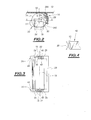
- FIG 1 there is shown a support 10 of a belt conveyor.
- the conveyor comprises a band 12 circulating resting on a set of tape supports arranged along the length of the conveyor.
- Each support 10 comprises a frame 14 adapted to be secured to a chassis not shown.
- Each support further comprises, in the embodiment shown, three rollers 16 rotatably mounted in a same plane with respect to the frame 14.
- the rollers 16 are carried by support legs 18 of the frame.
- the tabs 18 extend at each end of the rollers.
- the rollers 16 have a cylindrical lateral surface 20 of which the axis forms the axis of rotation of the roller.
- the roller has axially, at each end, support pins 22 projecting from the cylindrical surface 20 of the rollers.
- the cylindrical lateral surface of the roller is rotatable with respect to the pins. These can be trained by the ends of a single shaft running right through the roller.
- These trunnions are adapted to be engaged and immobilized, as illustrated on FIG. 2, in notches 24 formed in each of the legs 18.
- the pins For their immobilization in rotation relative to the legs 18, the pins have flats whose spacing is equal to the width of the notch.
- the notches 24 open along the front side wall of the legs 18 in a direction X-X extending generally parallel to the plane advancement of the strip 12 carried on the surface of the roller 16 associated.
- the front side wall is that found towards the front of the conveyor considering the direction of advancement of the carrier brown.
- the support 10 comprises, for each roller 16, a screen of protection 26.
- This screen 26 has a solid wall 28 extending along the length of the associated roller 16.
- means 30 for retaining the wall 28 on the lugs 18.
- the screen 28 further comprises means 32 for confinement of the nipples 22 in the associated notches.
- the screen 28 is formed for example from plastic.
- the wall 28 has come of material, at each of its ends, with fixing wings 34 on the legs 12.
- the wall 28 is connected to one end of each of the wings by a set of elastic strips 36.
- the legs 34 extend perpendicular to the wall 28, that is to say perpendicular to the axis of the associated roller 16.
- each tab 34 has an extension 38 forming a handle for supporting the fingers to remove the protective screen 26.
- the means 32 for confining the associated journal comprise a blade 40 extending parallel to the wing 34 on the side of the wing facing the roller.
- the blade 40 is linked at a first end, to the wall 28 and has a second free adapted to apply against the surface of a journal of the roller.
- the wing 34 and the blade 40 define a receiving groove 42 from the front edge of lug 18 considering the direction of travel of the conveyor.
- a projection 44 is arranged over most of the height of the wing 34 in look of the groove 42, the projection being formed at a distance from the bottom of the groove equal to the width of the tab 18.
- the projection 44 is adapted to ensure mechanical retention of the wing on the associated tab, by elastic engagement of the projection 44 along the rear edge of the tab 18 by considering the direction of advance of the strip.
- the wing 34 has, in its face turned towards the roller, a recess circular 46 for receiving the end of the journal 22 of the roller.
- the tab 40 has, at its end free, a concave profile 50 of shape complementary to the pin 22.
- This surface 50 constitutes a radial bearing surface on the pin 22 in order to press it against the bottom of the notch 24.
- the blade 40 Near its end, the blade 40 has a light 52 adapted to allow elastic deformation of its free end and thus elastically biasing the pin 22.
- the wall 28 of the screen has an upper longitudinal edge 28A and a lower edge 28B.
- the means 30 for retaining the wall 28 are adapted to maintain this, so that the upper edge 28A extends immediately below of the strip 12. The upper edge 28A and the contact edge between the strip and roller 16 then extend substantially along the displacement plane Of the band.
- the retaining means are adapted to maintain the edge 28B lightly supported on the lateral surface 20 of the roller in order to ensure a scraping of it.
- the tape support according to the invention is of a relatively structure simple since the protection screen ensures both protection of the roller and holding the roller on the support legs 12.
- the elastic blade 40 ensures locking and holding under pressure of the pins 22 against the bottom of the notches 24.
- the pressure exerted on the pins is obtained by slight deformation elastic of the ends of the blades 40.
- the screen For the installation of the screen, it is engaged from the side of the roller, while the wings 34 are spaced apart from one another.
- the wings 34 are released so that the projections 44 engage elastically behind the legs 12 thus ensuring a retention in position from screen 26.
- the screen 26 is easily removed by releasing the wings 34 by acting on the handles 38. After removal of the screen 26, the damaged roller can be easily released by moving the pins along the length of the notches 24. The axis of the notches extending parallel to the displacement plane tape, the roll can be removed without the tape having to to be raised. Likewise, the repaired roller, or a new roller may be easily reintroduced without the need to lift the band.
Applications Claiming Priority (2)
| Application Number | Priority Date | Filing Date | Title |
|---|---|---|---|
| FR0106536 | 2001-05-17 | ||
| FR0106536A FR2824815B1 (fr) | 2001-05-17 | 2001-05-17 | Support de bande de convoyeur et convoyeur le comportant |
Publications (2)
| Publication Number | Publication Date |
|---|---|
| EP1260461A1 true EP1260461A1 (de) | 2002-11-27 |
| EP1260461B1 EP1260461B1 (de) | 2004-04-14 |
Family
ID=8863409
Family Applications (1)
| Application Number | Title | Priority Date | Filing Date |
|---|---|---|---|
| EP02291205A Expired - Lifetime EP1260461B1 (de) | 2001-05-17 | 2002-05-15 | Tragelement eines Bandförderers und Förderer mit einem solchen Element |
Country Status (4)
| Country | Link |
|---|---|
| EP (1) | EP1260461B1 (de) |
| AT (1) | ATE264244T1 (de) |
| DE (1) | DE60200363T2 (de) |
| FR (1) | FR2824815B1 (de) |
Families Citing this family (3)
| Publication number | Priority date | Publication date | Assignee | Title |
|---|---|---|---|---|
| FR2923213B1 (fr) * | 2007-11-06 | 2010-04-09 | Rene Brunone | Station de support pour une bande de convoyage avec demontage des rouleaux facilites |
| DE202015105558U1 (de) * | 2015-10-20 | 2017-01-23 | Artur Küpper GmbH & Co. KG | Tragrollengestell mit waagerecht ausgerichteten Führungs- und Halteschlitzen |
| DE202015105592U1 (de) * | 2015-10-21 | 2017-01-27 | Artur Küpper GmbH & Co. KG | Tragrollengestell mit Schwenkrahmen und waagerecht ausgerichteten Führungs- und Halteschlitzen |
Citations (4)
| Publication number | Priority date | Publication date | Assignee | Title |
|---|---|---|---|---|
| GB225969A (en) * | 1923-10-01 | 1924-12-18 | Robert Black | Improvements relating to guards for machine rollers |
| FR2655628A1 (fr) * | 1989-12-09 | 1991-06-14 | Mueller Masch Stahlbau Gmbh | Dispositif destine a se proteger vis a vis de rouleaux de bandes convoyeuses. |
| FR2738230A3 (fr) * | 1995-09-02 | 1997-03-07 | Bosch Gmbh Robert | Dispositif pour recevoir au moins un rouleau de transport |
| FR2782989A1 (fr) * | 1998-09-07 | 2000-03-10 | Ibs Services De Bandes Transpo | Station de securite pour convoyeur a courroie |
-
2001
- 2001-05-17 FR FR0106536A patent/FR2824815B1/fr not_active Expired - Fee Related
-
2002
- 2002-05-15 AT AT02291205T patent/ATE264244T1/de not_active IP Right Cessation
- 2002-05-15 DE DE60200363T patent/DE60200363T2/de not_active Expired - Fee Related
- 2002-05-15 EP EP02291205A patent/EP1260461B1/de not_active Expired - Lifetime
Patent Citations (4)
| Publication number | Priority date | Publication date | Assignee | Title |
|---|---|---|---|---|
| GB225969A (en) * | 1923-10-01 | 1924-12-18 | Robert Black | Improvements relating to guards for machine rollers |
| FR2655628A1 (fr) * | 1989-12-09 | 1991-06-14 | Mueller Masch Stahlbau Gmbh | Dispositif destine a se proteger vis a vis de rouleaux de bandes convoyeuses. |
| FR2738230A3 (fr) * | 1995-09-02 | 1997-03-07 | Bosch Gmbh Robert | Dispositif pour recevoir au moins un rouleau de transport |
| FR2782989A1 (fr) * | 1998-09-07 | 2000-03-10 | Ibs Services De Bandes Transpo | Station de securite pour convoyeur a courroie |
Also Published As
| Publication number | Publication date |
|---|---|
| DE60200363D1 (de) | 2004-05-19 |
| FR2824815B1 (fr) | 2003-08-29 |
| DE60200363T2 (de) | 2005-05-12 |
| EP1260461B1 (de) | 2004-04-14 |
| FR2824815A1 (fr) | 2002-11-22 |
| ATE264244T1 (de) | 2004-04-15 |
Similar Documents
| Publication | Publication Date | Title |
|---|---|---|
| BE1004897A3 (fr) | Dispositif de fermeture, de separation ou de couverture. | |
| CA2494426C (fr) | Convoyeur | |
| EP2122102B1 (de) | Vorrichtung mit flexiblem vorhang | |
| EP0256926B1 (de) | Stauförderer | |
| FR2900139A1 (fr) | Station de support d'un convoyeur a bande et convoyeur la comportant | |
| WO2010004233A1 (fr) | Dispositif de serrage comprenant un collier | |
| WO2016124728A1 (fr) | Frein à disque comportant au moins un ressort de rappel élastique d'un patin de freinage, ressort de rappel élastique, et kit de remplacement | |
| EP3932833B1 (de) | Stützstruktur, bandförderer und herstellungsverfahren einer solchen stützstruktur | |
| EP1260461B1 (de) | Tragelement eines Bandförderers und Förderer mit einem solchen Element | |
| EP0468841B1 (de) | Bandförderer | |
| EP2058249A1 (de) | Stützstation für ein Förderband mit entfernbaren Walzen | |
| FR2771080A1 (fr) | Convoyeur a bande sans fin motorisee | |
| FR2460690A1 (fr) | Frein de ski | |
| FR2928143A1 (fr) | Convoyeur equipe de supports pour le montage d'elements tels qu'un rail de guidage lateral de charges | |
| EP2158375B1 (de) | Hochschiebesicherung für Rollläden | |
| EP1059415B1 (de) | Gurtaufroller, Rolladen- oder Storebetätigungsmechanismus mit einem solchen Aufroller und Verfahren zur Herstellung eines solchen Aufrollers | |
| EP0156736A1 (de) | Profilierter Dichtungsstreifen, insbesondere für Fahrzeugschiebetüren | |
| FR2581372A1 (fr) | Extenseur de courroie | |
| CA2404223A1 (fr) | Dispositif perfectionne de centrage automatique sur convoyeurs a bandes | |
| EP0670408B1 (de) | Deflektor für den unteren Querbalken eines Tür- oder Fensterrahmens oder dergleichen | |
| FR2975678A1 (fr) | Convoyeur satellite pour un systeme de convoyage | |
| FR2853218A1 (fr) | Ensemble de fenetre comprenant une tringle | |
| FR2928142A1 (fr) | Convoyeurs a rouleaux entraines | |
| FR2857688A1 (fr) | Porte a repliement et dispositif de guidage de rideau | |
| EP2199235B1 (de) | Hilfsstation eines Bandförderers |
Legal Events
| Date | Code | Title | Description |
|---|---|---|---|
| PUAI | Public reference made under article 153(3) epc to a published international application that has entered the european phase |
Free format text: ORIGINAL CODE: 0009012 |
|
| AK | Designated contracting states |
Kind code of ref document: A1 Designated state(s): AT BE CH CY DE DK ES FI FR GB GR IE IT LI LU MC NL PT SE TR |
|
| AX | Request for extension of the european patent |
Free format text: AL;LT;LV;MK;RO;SI |
|
| 17P | Request for examination filed |
Effective date: 20030116 |
|
| GRAH | Despatch of communication of intention to grant a patent |
Free format text: ORIGINAL CODE: EPIDOS IGRA |
|
| AKX | Designation fees paid |
Designated state(s): AT BE CH CY DE DK ES FI FR GB GR IE IT LI LU NL PT SE TR |
|
| GRAS | Grant fee paid |
Free format text: ORIGINAL CODE: EPIDOSNIGR3 |
|
| GRAA | (expected) grant |
Free format text: ORIGINAL CODE: 0009210 |
|
| AK | Designated contracting states |
Kind code of ref document: B1 Designated state(s): AT BE CH CY DE DK ES FI FR GB GR IE IT LI LU NL PT SE TR |
|
| PG25 | Lapsed in a contracting state [announced via postgrant information from national office to epo] |
Ref country code: IT Free format text: LAPSE BECAUSE OF FAILURE TO SUBMIT A TRANSLATION OF THE DESCRIPTION OR TO PAY THE FEE WITHIN THE PRESCRIBED TIME-LIMIT;WARNING: LAPSES OF ITALIAN PATENTS WITH EFFECTIVE DATE BEFORE 2007 MAY HAVE OCCURRED AT ANY TIME BEFORE 2007. THE CORRECT EFFECTIVE DATE MAY BE DIFFERENT FROM THE ONE RECORDED. Effective date: 20040414 Ref country code: IE Free format text: LAPSE BECAUSE OF FAILURE TO SUBMIT A TRANSLATION OF THE DESCRIPTION OR TO PAY THE FEE WITHIN THE PRESCRIBED TIME-LIMIT Effective date: 20040414 Ref country code: TR Free format text: LAPSE BECAUSE OF FAILURE TO SUBMIT A TRANSLATION OF THE DESCRIPTION OR TO PAY THE FEE WITHIN THE PRESCRIBED TIME-LIMIT Effective date: 20040414 Ref country code: FI Free format text: LAPSE BECAUSE OF FAILURE TO SUBMIT A TRANSLATION OF THE DESCRIPTION OR TO PAY THE FEE WITHIN THE PRESCRIBED TIME-LIMIT Effective date: 20040414 Ref country code: NL Free format text: LAPSE BECAUSE OF FAILURE TO SUBMIT A TRANSLATION OF THE DESCRIPTION OR TO PAY THE FEE WITHIN THE PRESCRIBED TIME-LIMIT Effective date: 20040414 Ref country code: CY Free format text: LAPSE BECAUSE OF FAILURE TO SUBMIT A TRANSLATION OF THE DESCRIPTION OR TO PAY THE FEE WITHIN THE PRESCRIBED TIME-LIMIT Effective date: 20040414 Ref country code: ES Free format text: LAPSE BECAUSE OF FAILURE TO SUBMIT A TRANSLATION OF THE DESCRIPTION OR TO PAY THE FEE WITHIN THE PRESCRIBED TIME-LIMIT Effective date: 20040414 Ref country code: AT Free format text: LAPSE BECAUSE OF FAILURE TO SUBMIT A TRANSLATION OF THE DESCRIPTION OR TO PAY THE FEE WITHIN THE PRESCRIBED TIME-LIMIT Effective date: 20040414 |
|
| REG | Reference to a national code |
Ref country code: GB Ref legal event code: FG4D Free format text: NOT ENGLISH |
|
| REG | Reference to a national code |
Ref country code: CH Ref legal event code: EP |
|
| PG25 | Lapsed in a contracting state [announced via postgrant information from national office to epo] |
Ref country code: LU Free format text: LAPSE BECAUSE OF NON-PAYMENT OF DUE FEES Effective date: 20040515 |
|
| REF | Corresponds to: |
Ref document number: 60200363 Country of ref document: DE Date of ref document: 20040519 Kind code of ref document: P |
|
| REG | Reference to a national code |
Ref country code: IE Ref legal event code: FG4D Free format text: FRENCH |
|
| PG25 | Lapsed in a contracting state [announced via postgrant information from national office to epo] |
Ref country code: BE Free format text: LAPSE BECAUSE OF NON-PAYMENT OF DUE FEES Effective date: 20040531 |
|
| GBT | Gb: translation of ep patent filed (gb section 77(6)(a)/1977) |
Effective date: 20040525 |
|
| PG25 | Lapsed in a contracting state [announced via postgrant information from national office to epo] |
Ref country code: DK Free format text: LAPSE BECAUSE OF FAILURE TO SUBMIT A TRANSLATION OF THE DESCRIPTION OR TO PAY THE FEE WITHIN THE PRESCRIBED TIME-LIMIT Effective date: 20040714 Ref country code: SE Free format text: LAPSE BECAUSE OF FAILURE TO SUBMIT A TRANSLATION OF THE DESCRIPTION OR TO PAY THE FEE WITHIN THE PRESCRIBED TIME-LIMIT Effective date: 20040714 Ref country code: GR Free format text: LAPSE BECAUSE OF FAILURE TO SUBMIT A TRANSLATION OF THE DESCRIPTION OR TO PAY THE FEE WITHIN THE PRESCRIBED TIME-LIMIT Effective date: 20040714 |
|
| NLV1 | Nl: lapsed or annulled due to failure to fulfill the requirements of art. 29p and 29m of the patents act | ||
| BERE | Be: lapsed |
Owner name: BRUNONE, RENE Effective date: 20040531 |
|
| REG | Reference to a national code |
Ref country code: IE Ref legal event code: FD4D |
|
| PLBE | No opposition filed within time limit |
Free format text: ORIGINAL CODE: 0009261 |
|
| STAA | Information on the status of an ep patent application or granted ep patent |
Free format text: STATUS: NO OPPOSITION FILED WITHIN TIME LIMIT |
|
| 26N | No opposition filed |
Effective date: 20050117 |
|
| PG25 | Lapsed in a contracting state [announced via postgrant information from national office to epo] |
Ref country code: LI Free format text: LAPSE BECAUSE OF NON-PAYMENT OF DUE FEES Effective date: 20060531 Ref country code: CH Free format text: LAPSE BECAUSE OF NON-PAYMENT OF DUE FEES Effective date: 20060531 |
|
| PGFP | Annual fee paid to national office [announced via postgrant information from national office to epo] |
Ref country code: DE Payment date: 20060607 Year of fee payment: 5 |
|
| PGFP | Annual fee paid to national office [announced via postgrant information from national office to epo] |
Ref country code: GB Payment date: 20060620 Year of fee payment: 5 |
|
| REG | Reference to a national code |
Ref country code: CH Ref legal event code: PL |
|
| PG25 | Lapsed in a contracting state [announced via postgrant information from national office to epo] |
Ref country code: PT Free format text: LAPSE BECAUSE OF NON-PAYMENT OF DUE FEES Effective date: 20040914 |
|
| GBPC | Gb: european patent ceased through non-payment of renewal fee |
Effective date: 20070515 |
|
| PG25 | Lapsed in a contracting state [announced via postgrant information from national office to epo] |
Ref country code: DE Free format text: LAPSE BECAUSE OF NON-PAYMENT OF DUE FEES Effective date: 20071201 |
|
| PGFP | Annual fee paid to national office [announced via postgrant information from national office to epo] |
Ref country code: FR Payment date: 20070530 Year of fee payment: 6 |
|
| PG25 | Lapsed in a contracting state [announced via postgrant information from national office to epo] |
Ref country code: GB Free format text: LAPSE BECAUSE OF NON-PAYMENT OF DUE FEES Effective date: 20070515 |
|
| REG | Reference to a national code |
Ref country code: FR Ref legal event code: ST Effective date: 20090119 |
|
| PG25 | Lapsed in a contracting state [announced via postgrant information from national office to epo] |
Ref country code: FR Free format text: LAPSE BECAUSE OF NON-PAYMENT OF DUE FEES Effective date: 20080602 |