EP1260308B1 - Werkzeugmaschine mit Späne-Absaugung - Google Patents
Werkzeugmaschine mit Späne-Absaugung Download PDFInfo
- Publication number
- EP1260308B1 EP1260308B1 EP01112648A EP01112648A EP1260308B1 EP 1260308 B1 EP1260308 B1 EP 1260308B1 EP 01112648 A EP01112648 A EP 01112648A EP 01112648 A EP01112648 A EP 01112648A EP 1260308 B1 EP1260308 B1 EP 1260308B1
- Authority
- EP
- European Patent Office
- Prior art keywords
- machine tool
- suction hood
- spindle
- tool according
- tool
- Prior art date
- Legal status (The legal status is an assumption and is not a legal conclusion. Google has not performed a legal analysis and makes no representation as to the accuracy of the status listed.)
- Expired - Lifetime
Links
- 238000006073 displacement reaction Methods 0.000 claims description 8
- 230000004308 accommodation Effects 0.000 claims 1
- 238000000605 extraction Methods 0.000 description 5
- 238000003754 machining Methods 0.000 description 5
- 230000001681 protective effect Effects 0.000 description 5
- 230000000712 assembly Effects 0.000 description 3
- 238000000429 assembly Methods 0.000 description 3
- 238000005553 drilling Methods 0.000 description 2
- 239000012530 fluid Substances 0.000 description 2
- 230000035515 penetration Effects 0.000 description 2
- 238000003825 pressing Methods 0.000 description 2
- 230000001419 dependent effect Effects 0.000 description 1
- 230000000694 effects Effects 0.000 description 1
- 230000005484 gravity Effects 0.000 description 1
- 238000003801 milling Methods 0.000 description 1
- 238000005096 rolling process Methods 0.000 description 1
Images



Classifications
-
- B—PERFORMING OPERATIONS; TRANSPORTING
- B23—MACHINE TOOLS; METAL-WORKING NOT OTHERWISE PROVIDED FOR
- B23Q—DETAILS, COMPONENTS, OR ACCESSORIES FOR MACHINE TOOLS, e.g. ARRANGEMENTS FOR COPYING OR CONTROLLING; MACHINE TOOLS IN GENERAL CHARACTERISED BY THE CONSTRUCTION OF PARTICULAR DETAILS OR COMPONENTS; COMBINATIONS OR ASSOCIATIONS OF METAL-WORKING MACHINES, NOT DIRECTED TO A PARTICULAR RESULT
- B23Q11/00—Accessories fitted to machine tools for keeping tools or parts of the machine in good working condition or for cooling work; Safety devices specially combined with or arranged in, or specially adapted for use in connection with, machine tools
- B23Q11/08—Protective coverings for parts of machine tools; Splash guards
- B23Q11/0825—Relatively slidable coverings, e.g. telescopic
-
- B—PERFORMING OPERATIONS; TRANSPORTING
- B23—MACHINE TOOLS; METAL-WORKING NOT OTHERWISE PROVIDED FOR
- B23Q—DETAILS, COMPONENTS, OR ACCESSORIES FOR MACHINE TOOLS, e.g. ARRANGEMENTS FOR COPYING OR CONTROLLING; MACHINE TOOLS IN GENERAL CHARACTERISED BY THE CONSTRUCTION OF PARTICULAR DETAILS OR COMPONENTS; COMBINATIONS OR ASSOCIATIONS OF METAL-WORKING MACHINES, NOT DIRECTED TO A PARTICULAR RESULT
- B23Q11/00—Accessories fitted to machine tools for keeping tools or parts of the machine in good working condition or for cooling work; Safety devices specially combined with or arranged in, or specially adapted for use in connection with, machine tools
- B23Q11/0042—Devices for removing chips
- B23Q11/0046—Devices for removing chips by sucking
-
- B—PERFORMING OPERATIONS; TRANSPORTING
- B23—MACHINE TOOLS; METAL-WORKING NOT OTHERWISE PROVIDED FOR
- B23Q—DETAILS, COMPONENTS, OR ACCESSORIES FOR MACHINE TOOLS, e.g. ARRANGEMENTS FOR COPYING OR CONTROLLING; MACHINE TOOLS IN GENERAL CHARACTERISED BY THE CONSTRUCTION OF PARTICULAR DETAILS OR COMPONENTS; COMBINATIONS OR ASSOCIATIONS OF METAL-WORKING MACHINES, NOT DIRECTED TO A PARTICULAR RESULT
- B23Q11/00—Accessories fitted to machine tools for keeping tools or parts of the machine in good working condition or for cooling work; Safety devices specially combined with or arranged in, or specially adapted for use in connection with, machine tools
- B23Q11/08—Protective coverings for parts of machine tools; Splash guards
- B23Q11/0883—Protective coverings for parts of machine tools; Splash guards for spindles, e.g. for their bearings or casings
Definitions
- the invention relates to a machine tool according to the preamble of Claim 1.
- machine tool is a box-shaped suction hood slidable on the tool spindle arranged.
- the suction hood has to be machined at her Workpiece facing edge on an annular chamber in which an overpressure gas cushion is located so that a narrow gap between the Extraction hood and the workpiece to be machined is formed.
- the Extraction hood itself is under gravity by means of the gas cushion on Workpiece.
- the interior of the suction hood is located on a vacuum source on, so that sucked with the air chips.
- On the Tool spindle stops are attached, which function as end stops have to pull off the suction hood from the vertical Tool spindle to avoid.
- a machine tool which only a movement of the tool in one direction, namely in the direction of Spindle axis permits. It is a telescope surrounding the tool trained suction hood provided during machining of a workpiece by means of a drill on the workpiece and during penetration of the drill into the workpiece against the force of a spring to the machine tool is postponed. Such a configuration leaves a three-dimensional Movement of the tool against the workpiece not to.
- the invention is based on the object, a machine tool of generic type with simple measures in such a way that a reliable chip extraction even with three-dimensional movements between the tool and the workpiece are possible, and that on the other hand the tool holder for tool change is freely accessible.
- FIG. 1 How particular Fig. 1 can be removed, which has shown in the drawing Machine tool one - seen in the horizontal z-direction - About square, formed by a frame 1 stand 2. Of the Stand 2 is supported on a base frame 3. On the work page 4 is supported on the base frame 3, a workpiece carrier 5, in the z-direction can be displaced in the usual way.
- each parallel mutually arranged x-guide rails 7 attached.
- Figure 7 is a x-slide horizontally displaceable in the x-direction 8 with guide shoes 9 stored.
- the x-carriage 8 is also formed like a frame and has a substantially vertical in the y-direction extending, open in the z direction through opening 10.
- the z-slide 14 carries a about a running in the z-direction spindle axis 17 rotatably driven tool spindle 18.
- the drive of the carriage 8, 12, 14 takes place by means of linear motors, for example, as in the EP application 01 105 919.3 is shown and described are configured.
- linear motors for driving the x-slide 8 are in Fig. 1st Permanent magnet arrangements 19 as a secondary part of the linear motors shown, which extend over the full working path of the x-carriage 8 and are attached to the front side 6 of the stator 2.
- the assigned Primary parts, which are stator coils, are on the the permanent magnet assemblies 19 facing sides of the x-carriage 8 attached and not visible in the drawing.
- linear motors provided by attached to y-slide 12 permanent magnet assemblies 22 as secondary parts and assigned, on the z-slide 14 mounted, serving as primary parts stator coils 23 formed are.
- the tool spindle 18 can also be in the z-direction immovable and instead of the workpiece carrier 5 in the z direction be displaceable. It is crucial that tool spindle 18 and Workpiece carrier 5 are displaceable relative to each other in the z-direction.
- the tool spindle 18 is in one firmly connected to the z-carriage 14 support tube 24 by means of rolling bearings 25 rotatably supported about the spindle axis 17.
- a tool holder 26 for receiving a tool 27 mounted by means of a on the workpiece carrier 5 attached workpiece 28 is to be processed.
- This hood 29 has a means a bearing 30 on the support tube 24 slidably supported inner tube 31 and on this in the direction of the spindle axis 17 slidably guided Outer tube 32 on.
- the displaceability of the outer tube 32 the inner tube 31 is limited by stops 33, 34.
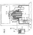
- On the outer tube 32 is a protective tube projecting beyond this toward the workpiece 28 35 attached, which is interchangeable and serves as a wear part. To that Protective tube 35 easy to replace, it is by means of only in Fig. 3rd illustrated clamping devices 35 a mounted on the outer tube 32.
- the protective tube 35 points to the workpiece 28th facing side extending over its full cross-section Opening 36.
- a suction tube 37 To the outer tube 32 is a suction tube 37 by means a manifold 38 connected.
- the suction tube 37 faces the z-slide 14 a sliding sleeve 39 so that it moves sliding of the outer tube 32 in the z-direction can follow.
- the outer tube 32 is formed by means of a sliding drive designed as a linear drive 40 with respect to the tool spindle 18 in the z direction displaceable.
- a sliding drive designed as a linear drive 40 with respect to the tool spindle 18 in the z direction displaceable.
- it consists of a controllable electric motor 41 with an integrated measuring device 41a, for example a conventional pulse generator, and one of these via a gear rack drive 42 drivable push rod 43, which extends in the z-direction and is secured to the outer tube 32.
- a controllable electric motor 41 with an integrated measuring device 41a, for example a conventional pulse generator, and one of these via a gear rack drive 42 drivable push rod 43, which extends in the z-direction and is secured to the outer tube 32.
- the Motor 41 is mounted in the z-carriage 14. He is from the central programmable Controlled control 44 of the machine tool. The control via a control line 45.
- a feedback line 46 is provided for the
- the hood 29 is in the extended working position shown in Fig. 2.
- the suction pipe 37 is connected to a suction pump, not shown, the Air through the gap 49 between the tool 27 facing surface 50 of the workpiece 28 and the protective tube 35 in the interior 51 of the Suction hood 29 sucks.
- the chips produced during processing become taken by the directed into the suction pipe 37 air flow, wherein the conveying movement supported by the fan blades 48 on the tool 27 becomes.
- the resulting chips are outward to the suction pipe 37 thrown.
- the tool 27 should be replaced, especially if it is automatic is to be replaced by a tool-changing device is the outer tube 32 with protective tube 35 by means of the displacement drive so far back into the illustrated in Fig. 3 tool change position, that the tool holder 26 for such a tool changing device is freely accessible. Again, the data in the controller 44 filed. In this sliding movement of the outer tube 32nd the suction tube 37 is inserted into the sliding sleeve 39.
- the suction hood 29 must during penetration of the drill in the workpiece 28 according to the relative feed of the drill be withdrawn. These data are stored in the controller 44.
- the embodiment according to FIG. 5 differs from that according to FIGS. 2 and 3 only by the shift drive 40 '.
- the cylinder 54 is connected on both sides of the piston 55 to fluid lines 56, 57, via a control valve 57a with a pressure fluid source, not shown are connected.
- the position of the suction hood 29 in the working position immediately before the workpiece 28 on the one hand and moved back to the tool change Tool change position is limited by stops 58, 59,
- the adjustable and lockable on a parallel to the spindle axis 17 extending guide rod 60 are mounted, namely the stop 59 for the working position and the stop 58 for the tool change position.
- This is on the one hand connected to the outer tube 32 and guided in the z-carriage 14, against which the stops 58, 59 each in one of their two described positions come to the plant. in this connection
- the position of the suction hood 29 each by hand for a set certain machining process.
Landscapes
- Engineering & Computer Science (AREA)
- Mechanical Engineering (AREA)
- Auxiliary Devices For Machine Tools (AREA)
Description
- Fig. 1
- eine Werkzeugmaschine in Vorderansicht,
- Fig. 2
- eine Schnitt-Darstellung der Werkzeugmaschine entsprechend der Schnittlinie II-II in Fig. 4 mit ausgefahrener Absaug-Haube,
- Fig. 3
- eine Schnitt-Darstellung der Werkzeugmaschine entsprechend der Schnittlinie II-II in Fig. 4 mit zurückgezogener Absaug-Haube,
- Fig. 4
- eine Stirnansicht auf die Absaug-Haube mit Werkzeug und
- Fig. 5
- eine Darstellung entsprechend Fig. 2 und 3 mit einem gegenüber Fig. 2 und 3 abgewandelten Verschiebe-Antrieb für die Absaug-Haube.
Claims (11)
- Werkzeugmaschine,dadurch gekennzeichnet, dass zur Verschiebung der Absaug-Haube (29) ein Verschiebe-Antrieb (40, 40') vorgesehen ist undmit einer um eine Spindel-Achse (17) drehbaren Werkzeug-Spindel (18),die an einem Ende eine Werkzeug-Aufnahme (26) zur Befestigung eines Werkzeugs (27) aufweist, unddie in einem Tragrohr (24) drehbar gelagert ist,mit einem Werkstückträger (5) zur Aufnahme eines mittels des Werkzeugs (27) zu bearbeitenden Werkstücks (28),mit einem Antrieb (22, 23) zur Verschiebung des Werkstückträgers (5) und der Werkzeug-Spindel (18) relativ zueinander in Richtung der Werkzeug-Spindel (18),mit einer Einrichtung zur Verschiebung des Werkzeugs (27) und des Werkstücks (28) relativ zueinander in mindestens einer Richtung quer zur Spindel-Achse (17),mit einer Absaug-Haube (29),die das Werkzeug (27) umgibt unddie relativ zur Werkzeug-Spindel (18) in Richtung der Spindel-Achse (17) auf dem Tragrohr (24) in eine ausgefahrene Arbeits-Position verschiebbar angeordnet ist undmit Mitteln zur Erzeugung eines Spalts (49) zwischen der Absaug-Haube (29) und dem Werkstück (28) in der Arbeits-Position der Absaug-Haube (29),
dass die Mittel zur Erzeugung eines Spalts (49) als mittel zur Einstellung des Spalts (49) in der Arbeits-Position und/oder zum Ansteuern der Werkzeugwechsel-Position durch eine Steuerung (44) des Verschiebe-Antriebs (40) oder durch einstellbare Anschläge (58, 59) gebildet sind. - Werkzeugmaschine nach Anspruch 1, dadurch gekennzeichnet, dass die Absaug-Haube (29) in eine zurückgefahrene Werkzeugwechsel-Position verschiebbar ist.
- Werkzeugmaschine nach Anspruch 1, dadurch gekennzeichnet, dass der Verschiebe-Antrieb (40, 40') als Linear-Antrieb ausgebildet ist.
- Werkzeugmaschine nach Anspruch 3, dadurch gekennzeichnet, dass der Linear-Antrieb (40) durch einen Elektro-Motor (41) mit einer Schubstange (43) gebildet ist.
- Werkzeugmaschine nach Anspruch 3, dadurch gekennzeichnet, dass der Linear-Antrieb (40') als fluidisch beaufschlagbarer Kolben-Zylinder-Antrieb (52) ausgebildet ist.
- Werkzeugmaschine nach Anspruch 1, dadurch gekennzeichnet, dass die Absaug-Haube (29) teleskopartig mit einem auf einem Innen-Rohr (31) verschiebbaren Außen-Rohr (32) ausgebildet ist.
- Werkzeugmaschine nach Anspruch 1, dadurch gekennzeichnet, dass die Absaug-Haube (29) mit einem auswechselbaren Schutzrohr (35) versehen ist.
- Werkzeugmaschine nach Anspruch 1, dadurch gekennzeichnet, dass die Absaug-Haube (29) mit einem in Richtung der Spindel-Achse (17) verschiebbaren Absaug-Rohr (37) versehen ist.
- Werkzeugmaschine nach Anspruch 1, dadurch gekennzeichnet, dass die Absaug-Haube (29) einen Kreisquerschnitt aufweist und an ihrem dem Werkstückträger (5) zugewandten Ende eine sich über den vollen Querschnitt erstreckende Öffnung (36) aufweist.
- Werkzeugmaschine nach Anspruch 1, dadurch gekennzeichnet, dass das Werkzeug (27) mit Lüfterflügeln (48) versehen ist.
- Werkzeugmaschine nach Anspruch 1, dadurch gekennzeichnet, dass die Spindel-Achse (17) horizontal angeordnet ist.
Priority Applications (3)
| Application Number | Priority Date | Filing Date | Title |
|---|---|---|---|
| ES01112648T ES2245659T3 (es) | 2001-05-25 | 2001-05-25 | Maquina herramienta con aspiracion de virutas. |
| EP01112648A EP1260308B1 (de) | 2001-05-25 | 2001-05-25 | Werkzeugmaschine mit Späne-Absaugung |
| DE50106890T DE50106890D1 (de) | 2001-05-25 | 2001-05-25 | Werkzeugmaschine mit Späne-Absaugung |
Applications Claiming Priority (1)
| Application Number | Priority Date | Filing Date | Title |
|---|---|---|---|
| EP01112648A EP1260308B1 (de) | 2001-05-25 | 2001-05-25 | Werkzeugmaschine mit Späne-Absaugung |
Publications (2)
| Publication Number | Publication Date |
|---|---|
| EP1260308A1 EP1260308A1 (de) | 2002-11-27 |
| EP1260308B1 true EP1260308B1 (de) | 2005-07-27 |
Family
ID=8177533
Family Applications (1)
| Application Number | Title | Priority Date | Filing Date |
|---|---|---|---|
| EP01112648A Expired - Lifetime EP1260308B1 (de) | 2001-05-25 | 2001-05-25 | Werkzeugmaschine mit Späne-Absaugung |
Country Status (3)
| Country | Link |
|---|---|
| EP (1) | EP1260308B1 (de) |
| DE (1) | DE50106890D1 (de) |
| ES (1) | ES2245659T3 (de) |
Families Citing this family (4)
| Publication number | Priority date | Publication date | Assignee | Title |
|---|---|---|---|---|
| ITBO20040218A1 (it) | 2004-04-16 | 2004-07-16 | Jobs Spa | Dispositivo aspirante per macchine utensili |
| US11565360B2 (en) * | 2018-06-04 | 2023-01-31 | Uwm Research Foundation, Inc. | Dust collection for cutting machine |
| CN113681343A (zh) * | 2021-07-29 | 2021-11-23 | 江苏永昊高强度螺栓有限公司 | 螺栓切割成型机的碎屑收集装置 |
| CN114034433B (zh) * | 2022-01-10 | 2022-03-15 | 烟台宏田汽车零部件股份有限公司 | 一种用于车辆制动盘的平衡测试系统 |
Family Cites Families (8)
| Publication number | Priority date | Publication date | Assignee | Title |
|---|---|---|---|---|
| US3837383A (en) * | 1972-11-09 | 1974-09-24 | K Ko | Dust collector and safety guard |
| DE2715378C2 (de) * | 1977-04-06 | 1985-12-19 | Robert Bosch Gmbh, 7000 Stuttgart | Vorrichtung für Handwerkzeugmaschinen zum Auffangen und Beseitigen beim Arbeiten abfallender Stoffe |
| DE8903065U1 (de) * | 1989-03-13 | 1989-06-08 | Ringler, Bernhard, 7076 Waldstetten | Vorrichtung zum Absaugen von auf Bearbeitungsmaschinen im Bereich eines rotierenden Bearbeitungswerkzeuges anfallenden Bearbeitungsrückständen, wie Feinspäne oder Stäube |
| DE19500215C1 (de) * | 1995-01-05 | 1996-05-30 | Fraunhofer Ges Forschung | Nibbelvorrichtung |
| DE19541011C1 (de) * | 1995-11-03 | 1997-04-24 | Wissner Rolf | Verfahren für die Steuerung einer Werkzeugmaschine mit einer Schutzhaube und Werkzeugmaschine |
| US6036412A (en) * | 1998-03-24 | 2000-03-14 | Dalla; Joseph E. | Coolant and chip removal apparatus for milling operations |
| SE9901946L (sv) * | 1999-05-28 | 2000-11-29 | Volvo Ab | Metod och anordning vid automatisk spånavverkande bearbetning av ett arbetsstycke |
| SE519272C2 (sv) * | 1999-05-28 | 2003-02-11 | Volvo Car Corp | Metod och anordning vid automatisk spånavverkande bearbetning av ett arbetsstycke |
-
2001
- 2001-05-25 EP EP01112648A patent/EP1260308B1/de not_active Expired - Lifetime
- 2001-05-25 ES ES01112648T patent/ES2245659T3/es not_active Expired - Lifetime
- 2001-05-25 DE DE50106890T patent/DE50106890D1/de not_active Expired - Lifetime
Also Published As
| Publication number | Publication date |
|---|---|
| EP1260308A1 (de) | 2002-11-27 |
| DE50106890D1 (de) | 2005-09-01 |
| ES2245659T3 (es) | 2006-01-16 |
Similar Documents
| Publication | Publication Date | Title |
|---|---|---|
| DE102011013850B4 (de) | Tiefbohrungsbearbeitungsvorrichtung | |
| EP0287071B1 (de) | Werkzeugwechselanordnung für Leiterplatten-Koordinatenbohr-maschinen | |
| EP0970770A1 (de) | Einrichtung sowie Verfahren zur Bearbeitung von Bohrungen | |
| EP2080589A1 (de) | Vorrichtung zum Bearbeiten, insbesondere Erodieren und Schleifen, von mit Schneiden versehenen Rotationswerkstücken | |
| DE20306087U1 (de) | Werkzeugmaschine mit Werkzeug-Magazin | |
| EP1997582B1 (de) | Verfahren zum Eichen eines Aufspanntisches | |
| EP1927429A1 (de) | Werkzeugmaschine mit Werkzeugmagazin | |
| DE602005004058T2 (de) | Staubabzugshaube für Werkzeugmaschinen | |
| DE4236866A1 (de) | Drehmaschine | |
| EP1210995B1 (de) | Maschine für die Bearbeitung von Werkstücken, insbesondere von Blechen, mit wenigstens einer Biegestation sowie wenigstens einer Fügevorrichtung | |
| DE19858791B4 (de) | Plattenbearbeitungsmaschine | |
| DE3245850C2 (de) | ||
| DE3427212A1 (de) | Tiefbohrmaschine | |
| EP3081324A1 (de) | Langdrehautomat mit zwei nc-gesteuerten bearbeitungsachsen und verfahren zum bearbeiten von werkstücken auf einem langdrehautomat mit zwei nc-gesteuerten bearbeitungsachsen | |
| EP1260308A1 (de) | Werkzeugmaschine mit Späne-Absaugung | |
| EP2165793B1 (de) | Maschine zum Bearbeiten von plattenartigen Werkstücken, insbesondere von Blechen sowie Werkzeugsatz für eine derartige Maschine und Verwendung eines Gewindefräswerkzeugs an einer derartigen Maschine | |
| DE102008025385B4 (de) | Palettenaustauscher | |
| DE3876017T2 (de) | Raeummaschine. | |
| DE69402599T2 (de) | Verfahren zur kontrollierten Spanabhebung bei Bohrfräser und Herstellung von Bohrfräser nach diesem Verfahren | |
| EP1733842B1 (de) | Verfahren zur spanenden Innen- und Aussen-Bearbeitung eines rohrförmigen Werkstücks und Vertikal-Drehmaschine zur Durchführung des Verfahrens | |
| EP1074333A2 (de) | Drehmaschine mit zwei Werkzeugträgersystemen | |
| EP1674200B1 (de) | Werkzeugmaschine mit Werkzeug-Bruch-Erfassungseinrichtung | |
| DE3412576C1 (de) | Fraes-Bohrvorrichtung | |
| DE1477580A1 (de) | Vorrichtung zur Bearbeitung von Werkstuecken,z.B. Bohrwerk | |
| DE10215241B4 (de) | Paletten-Wechseleinrichtung für eine Werkzeugmaschine |
Legal Events
| Date | Code | Title | Description |
|---|---|---|---|
| PUAI | Public reference made under article 153(3) epc to a published international application that has entered the european phase |
Free format text: ORIGINAL CODE: 0009012 |
|
| AK | Designated contracting states |
Kind code of ref document: A1 Designated state(s): AT BE CH CY DE DK ES FI FR GB GR IE IT LI LU MC NL PT SE TR |
|
| AX | Request for extension of the european patent |
Free format text: AL;LT;LV;MK;RO;SI |
|
| 17P | Request for examination filed |
Effective date: 20030206 |
|
| AKX | Designation fees paid |
Designated state(s): DE ES FR GB IT |
|
| 17Q | First examination report despatched |
Effective date: 20040812 |
|
| RAP1 | Party data changed (applicant data changed or rights of an application transferred) |
Owner name: CROSS HUELLER GMBH |
|
| GRAP | Despatch of communication of intention to grant a patent |
Free format text: ORIGINAL CODE: EPIDOSNIGR1 |
|
| GRAS | Grant fee paid |
Free format text: ORIGINAL CODE: EPIDOSNIGR3 |
|
| GRAA | (expected) grant |
Free format text: ORIGINAL CODE: 0009210 |
|
| AK | Designated contracting states |
Kind code of ref document: B1 Designated state(s): DE ES FR GB IT |
|
| REG | Reference to a national code |
Ref country code: GB Ref legal event code: FG4D Free format text: NOT ENGLISH |
|
| REF | Corresponds to: |
Ref document number: 50106890 Country of ref document: DE Date of ref document: 20050901 Kind code of ref document: P |
|
| GBT | Gb: translation of ep patent filed (gb section 77(6)(a)/1977) |
Effective date: 20051107 |
|
| REG | Reference to a national code |
Ref country code: ES Ref legal event code: FG2A Ref document number: 2245659 Country of ref document: ES Kind code of ref document: T3 |
|
| ET | Fr: translation filed | ||
| PLBE | No opposition filed within time limit |
Free format text: ORIGINAL CODE: 0009261 |
|
| STAA | Information on the status of an ep patent application or granted ep patent |
Free format text: STATUS: NO OPPOSITION FILED WITHIN TIME LIMIT |
|
| 26N | No opposition filed |
Effective date: 20060428 |
|
| PGFP | Annual fee paid to national office [announced via postgrant information from national office to epo] |
Ref country code: ES Payment date: 20100520 Year of fee payment: 10 Ref country code: FR Payment date: 20100608 Year of fee payment: 10 |
|
| PGFP | Annual fee paid to national office [announced via postgrant information from national office to epo] |
Ref country code: IT Payment date: 20100528 Year of fee payment: 10 |
|
| PGFP | Annual fee paid to national office [announced via postgrant information from national office to epo] |
Ref country code: GB Payment date: 20100521 Year of fee payment: 10 |
|
| REG | Reference to a national code |
Ref country code: DE Ref legal event code: R081 Ref document number: 50106890 Country of ref document: DE Owner name: MAG IAS GMBH, DE Free format text: FORMER OWNER: CROSS HUELLER GMBH, 71636 LUDWIGSBURG, DE Effective date: 20110223 |
|
| GBPC | Gb: european patent ceased through non-payment of renewal fee |
Effective date: 20110525 |
|
| REG | Reference to a national code |
Ref country code: FR Ref legal event code: ST Effective date: 20120131 |
|
| PG25 | Lapsed in a contracting state [announced via postgrant information from national office to epo] |
Ref country code: IT Free format text: LAPSE BECAUSE OF NON-PAYMENT OF DUE FEES Effective date: 20110525 |
|
| PG25 | Lapsed in a contracting state [announced via postgrant information from national office to epo] |
Ref country code: FR Free format text: LAPSE BECAUSE OF NON-PAYMENT OF DUE FEES Effective date: 20110531 |
|
| PG25 | Lapsed in a contracting state [announced via postgrant information from national office to epo] |
Ref country code: GB Free format text: LAPSE BECAUSE OF NON-PAYMENT OF DUE FEES Effective date: 20110525 |
|
| REG | Reference to a national code |
Ref country code: ES Ref legal event code: FD2A Effective date: 20121116 |
|
| PG25 | Lapsed in a contracting state [announced via postgrant information from national office to epo] |
Ref country code: ES Free format text: LAPSE BECAUSE OF NON-PAYMENT OF DUE FEES Effective date: 20110526 |
|
| PGFP | Annual fee paid to national office [announced via postgrant information from national office to epo] |
Ref country code: DE Payment date: 20150521 Year of fee payment: 15 |
|
| REG | Reference to a national code |
Ref country code: DE Ref legal event code: R119 Ref document number: 50106890 Country of ref document: DE |
|
| PG25 | Lapsed in a contracting state [announced via postgrant information from national office to epo] |
Ref country code: DE Free format text: LAPSE BECAUSE OF NON-PAYMENT OF DUE FEES Effective date: 20161201 |