EP1260273B1 - Vollmantel-Schneckenzentrifuge - Google Patents
Vollmantel-Schneckenzentrifuge Download PDFInfo
- Publication number
- EP1260273B1 EP1260273B1 EP02009098A EP02009098A EP1260273B1 EP 1260273 B1 EP1260273 B1 EP 1260273B1 EP 02009098 A EP02009098 A EP 02009098A EP 02009098 A EP02009098 A EP 02009098A EP 1260273 B1 EP1260273 B1 EP 1260273B1
- Authority
- EP
- European Patent Office
- Prior art keywords
- solid
- screw centrifuge
- centrifuge according
- bowl screw
- bowl
- Prior art date
- Legal status (The legal status is an assumption and is not a legal conclusion. Google has not performed a legal analysis and makes no representation as to the accuracy of the status listed.)
- Expired - Lifetime
Links
- 239000007788 liquid Substances 0.000 claims abstract description 17
- 239000000203 mixture Substances 0.000 claims abstract description 11
- 238000000926 separation method Methods 0.000 claims description 2
- 238000007599 discharging Methods 0.000 claims 3
- 238000005191 phase separation Methods 0.000 abstract description 2
- 230000006835 compression Effects 0.000 abstract 1
- 238000007906 compression Methods 0.000 abstract 1
- 239000012071 phase Substances 0.000 description 16
- 239000007787 solid Substances 0.000 description 16
- 239000007791 liquid phase Substances 0.000 description 9
- XLYOFNOQVPJJNP-UHFFFAOYSA-N water Substances O XLYOFNOQVPJJNP-UHFFFAOYSA-N 0.000 description 8
- 239000003921 oil Substances 0.000 description 7
- 235000019198 oils Nutrition 0.000 description 7
- 238000000605 extraction Methods 0.000 description 4
- 235000008390 olive oil Nutrition 0.000 description 4
- 239000004006 olive oil Substances 0.000 description 4
- 230000032258 transport Effects 0.000 description 4
- 235000015203 fruit juice Nutrition 0.000 description 3
- 239000007790 solid phase Substances 0.000 description 3
- 241000237858 Gastropoda Species 0.000 description 2
- 238000001035 drying Methods 0.000 description 2
- 230000000694 effects Effects 0.000 description 2
- 235000013305 food Nutrition 0.000 description 2
- 238000004519 manufacturing process Methods 0.000 description 2
- 210000000056 organ Anatomy 0.000 description 2
- 241001465754 Metazoa Species 0.000 description 1
- 241000207836 Olea <angiosperm> Species 0.000 description 1
- 210000004381 amniotic fluid Anatomy 0.000 description 1
- 239000010775 animal oil Substances 0.000 description 1
- 230000009286 beneficial effect Effects 0.000 description 1
- 239000002551 biofuel Substances 0.000 description 1
- 239000002131 composite material Substances 0.000 description 1
- 230000003247 decreasing effect Effects 0.000 description 1
- 238000002474 experimental method Methods 0.000 description 1
- 239000003925 fat Substances 0.000 description 1
- 230000009969 flowable effect Effects 0.000 description 1
- 235000011389 fruit/vegetable juice Nutrition 0.000 description 1
- 235000012055 fruits and vegetables Nutrition 0.000 description 1
- 238000010438 heat treatment Methods 0.000 description 1
- 239000010720 hydraulic oil Substances 0.000 description 1
- 238000000034 method Methods 0.000 description 1
- 239000002245 particle Substances 0.000 description 1
- 239000000126 substance Substances 0.000 description 1
- 230000007704 transition Effects 0.000 description 1
- 235000015112 vegetable and seed oil Nutrition 0.000 description 1
- 235000019871 vegetable fat Nutrition 0.000 description 1
- 235000015192 vegetable juice Nutrition 0.000 description 1
- 239000008158 vegetable oil Substances 0.000 description 1
- 239000002699 waste material Substances 0.000 description 1
Images

Classifications
-
- B—PERFORMING OPERATIONS; TRANSPORTING
- B04—CENTRIFUGAL APPARATUS OR MACHINES FOR CARRYING-OUT PHYSICAL OR CHEMICAL PROCESSES
- B04B—CENTRIFUGES
- B04B1/00—Centrifuges with rotary bowls provided with solid jackets for separating predominantly liquid mixtures with or without solid particles
- B04B1/20—Centrifuges with rotary bowls provided with solid jackets for separating predominantly liquid mixtures with or without solid particles discharging solid particles from the bowl by a conveying screw coaxial with the bowl axis and rotating relatively to the bowl
-
- B—PERFORMING OPERATIONS; TRANSPORTING
- B04—CENTRIFUGAL APPARATUS OR MACHINES FOR CARRYING-OUT PHYSICAL OR CHEMICAL PROCESSES
- B04B—CENTRIFUGES
- B04B1/00—Centrifuges with rotary bowls provided with solid jackets for separating predominantly liquid mixtures with or without solid particles
- B04B1/20—Centrifuges with rotary bowls provided with solid jackets for separating predominantly liquid mixtures with or without solid particles discharging solid particles from the bowl by a conveying screw coaxial with the bowl axis and rotating relatively to the bowl
- B04B2001/2041—Centrifuges with rotary bowls provided with solid jackets for separating predominantly liquid mixtures with or without solid particles discharging solid particles from the bowl by a conveying screw coaxial with the bowl axis and rotating relatively to the bowl with baffles, plates, vanes or discs attached to the conveying screw
Definitions
- the invention relates to a solid bowl screw centrifuge continuous separation of a multi-phase flowable mixture
- a multi-phase flowable mixture comprising one of a cylindrical and a conical drum with a composite rotor Discharge openings for the separate phases and one screw conveyor rotatable within the rotor for transport the most difficult phase to the corresponding discharge opening, wherein means for the feed of the mixture to be separated into the Centrifuge are provided and at least on the screw conveyor a baffle plate is attached.
- Screw centrifuges of this type are mainly used to get the purest possible olive oil from olives, the free of water and cloudy substances.
- Other uses in the food sector for example Manufacture of fruit and vegetable juices or extraction animal or vegetable oils and fats.
- IT-PS 675 801 describes a system for the extraction of Olive oil, the hydraulic oil used up to that point Should replace presses that did not allow continuous operation.
- the solution to this problem is to use a Centrifuge provided in which the solids and on the other hand, that of oil, water and small ones Existing liquid residue is withdrawn, the must then be fed to a separator.
- the experience has shown, however, that the liquid phase is still high Contained solids content, which is a complex and expensive After treatment required to the liquid phase of free the solid particles contained therein.
- the invention is therefore based on the object of a device to make available, which enables the share of liquid phase in the solid phase with constructive and economically little effort by a considerable proportion to reduce.
- the invention has surprisingly shown that one on the one hand compared to the previously used Two-phase systems get drier solid phase while on the other hand, the easier phase is very slight Contains solids, which, if necessary, subsequently can be easily separated.
- the extracted solid phase has a smaller olive oil Amount of amniotic fluid during the lighter phase there is largely solids-free oil and water and thus is more economically separable.
- the screw conveyor which is behind the baffle plate in the conveying direction lies, has one or more return openings, finds the liquid or solid separated from the solid Liquid mixture a way to subsequently under the Baffle plate through to the corresponding discharge openings flow back.
- These usually consist of a radial adjustable weir or an equivalent organ whose Opening width the desired level of the to be separated Liquid determined.
- the return opening can have any shape that it is the liquid Phase or the liquid phases allowed from the range of Screw conveyor that connects to the baffle plate to flow back there.
- a window can, for example, by one Section of the screw conveyor is generated, which as Band snail or as deviating from the circular shape Snail part is formed.
- Another option is there in opening the return port by an interruption in the To produce a spiral gear, for example by moving in Circumferential direction extending gap or in Circumferential discontinuity of the helical gear, the forms an overlap point.
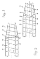
- a rotor 10 is a solid-bowl screw centrifuge 12 shown by one not shown, known drive is rotated.
- the rotor 10 consists of a cylindrical drum 14 and an adjoining, conical drum 16.
- a screw conveyor 18 is rotatably mounted, the Rotary drive is also not shown.
- the screw conveyor 18 is driven at a different speed than the rotor 10.
- the screw spiral 20 of the screw conveyor 18 is on one Hollow shaft 22 attached and arranged so that the Direction of conveyance from the cylindrical drum 14 to the conical Drum 16 takes place.
- the hollow shaft 22 over the entire length of the rotor 10 constant diameter.
- baffle plate 24 On the hollow shaft 22 is in the region of the transition from the cylindrical Drum 14 in the conical drum 16 a baffle plate 24 attached, the radially outer edge 26 of an annular Leaves passage opening 28 to the inner wall 30 of the rotor 10.
- the baffle plate 24 can also be on another Place the hollow shaft 22 to be fixed.
- the spiral path 42 of the screw conveyor 18 has the in the conveying direction according to the arrow 32 behind the Baffle plate 24 is located, return openings 44. It could be found that 44 through these return openings liquid portion in the solid 40, which is already in the range of conical drum 16 is again significantly reduced can be, obviously because the one separated there Liquid 46 a way back via the return openings 44 through the passage opening 28 in the area of the cylindrical Drum 14 takes place.
- Figure 2 shows a variant of Figure 1, in which the hollow shaft 22 does not have a constant diameter, but also conical in the area of the conical drum 18 is.
- the liquid phase again separates into a light and a medium phase, for example Oil and water or fruit juice / vegetable juice and water.
- a medium phase for example Oil and water or fruit juice / vegetable juice and water.
- the solid 40 that is discharged through the discharge opening 38 can be explained in a subordinate decanter Design to be further treated to the yield of "noble Phase "(oil, fruit juice, etc.) again and the Reduce the liquid content in the solid again.
- the centrifuge according to the invention can separate all multi-phase products are used.
- the centrifuge according to the invention can separate all multi-phase products are used.
Landscapes
- Centrifugal Separators (AREA)
Description
Claims (9)
- Vollmantel-Schneckenzentrifuge zum kontinuierlichen Trennen eines aus mehreren Phasen bestehenden, fließfähigen Gemisches, insbesondere eines Feststoff-Flüssigkeits-Gemisches, umfassend einen aus einer zylindrischen und einer konischen Trommel (14, 16) zusammengesetzten Rotor (10) mit Austragsöffnungen für die voneinander getrennten Phasen und eine innerhalb des Rotors drehbare Förderschnecke (18) für den Transport der schwersten Phase zu der entsprechenden Austragsöffnung (38), wobei Mittel für den Zulauf des zu trennenden Gemisches in die Zentrifuge vorgesehen sind und auf der Förderschnecke (18) wenigstens eine Stauscheibe (24) angebracht ist, dadurch gekennzeichnet, daß einer der Wendelgänge (42) der Förderschnecke (18), der in Förderrichtung hinter der Stauscheibe (24) liegt, wenigstens eine Rücklauföffnung (44) für die leichteren Phasen (46) aufweist.
- Vollmantel-Schneckenzentrifuge nach Anspruch 1, dadurch gekennzeichnet, daß die wenigstens eine Rücklauföffnung (44) in dem Wendelgang (42) vorgesehen ist, der unmittelbar hinter der Stauscheibe (24) liegt.
- Vollmantel-Schneckenzentrifuge nach Anspruch 1 oder 2, dadurch gekennzeichnet, daß die Rücklauföffnung (44) aus einem Fenster besteht.
- Vollmantel-Schneckenzentrifuge nach Anspruch 3, dadurch gekennzeichnet, daß der radial innere Rand des Fensters auf der Mantelfläche der die Förderschnecke (18) tragenden Welle (22) liegt.
- Vollmantel-Schneckenzentrifuge nach Anspruch 1, dadurch gekennzeichnet, daß die Rücklauföffnung (44) aus einer Unterbrechung des Wendelgangs (42) besteht.
- Vollmantel-Schneckenzentrifuge nach Anspruch 5, dadurch gekennzeichnet, daß die Unterbrechung durch einen sich in Umfangsrichtung der Förderschnecke (18) erstreckenden Spalt gebildet wird.
- Vollmantel-Schneckenzentrifuge nach Anspruch 5, dadurch gekennzeichnet, daß durch die Unterbrechung im Wendelgang (42) eine in Umfangsrichtung verlaufende Überlappung gebildet wird.
- Vollmantel-Schneckenzentrifuge nach einem der vorhergehenden Ansprüche, dadurch gekennzeichnet, daß die Förderschnecke (18) eine Welle (22) mit zwei unterschiedlichen Durchmessern hat, wobei die Stauscheibe (24) auf dem Abschnitt der Welle (22) mit größerem Durchmesser befestigt ist, während der die Rücklauföffnung (44) aufweisende Wendelgang (42) wenigstens teilweise auf dem sich daran über eine Stufe (52) anschließenden Abschnitt der Welle (22) mit kleinerem Durchmesser sitzt.
- Vollmantel-Schneckenzentrifuge nach einem der vorhergehenden Ansprüche, dadurch gekennzeichnet, daß der Austragsöffnung für die leichteren Phasen (46) ein Separator nachgeschaltet ist.
Applications Claiming Priority (2)
| Application Number | Priority Date | Filing Date | Title |
|---|---|---|---|
| DE10125096 | 2001-05-23 | ||
| DE10125096A DE10125096A1 (de) | 2001-05-23 | 2001-05-23 | Dekantierzentrifuge |
Publications (2)
| Publication Number | Publication Date |
|---|---|
| EP1260273A1 EP1260273A1 (de) | 2002-11-27 |
| EP1260273B1 true EP1260273B1 (de) | 2004-10-13 |
Family
ID=7685832
Family Applications (1)
| Application Number | Title | Priority Date | Filing Date |
|---|---|---|---|
| EP02009098A Expired - Lifetime EP1260273B1 (de) | 2001-05-23 | 2002-04-24 | Vollmantel-Schneckenzentrifuge |
Country Status (4)
| Country | Link |
|---|---|
| EP (1) | EP1260273B1 (de) |
| AT (1) | ATE279262T1 (de) |
| DE (2) | DE10125096A1 (de) |
| ES (1) | ES2229006T3 (de) |
Cited By (3)
| Publication number | Priority date | Publication date | Assignee | Title |
|---|---|---|---|---|
| CN100467132C (zh) * | 2003-06-18 | 2009-03-11 | 阿尔法拉瓦尔股份有限公司 | 用于沉降式离心机的螺旋式输送器 |
| CN110382118A (zh) * | 2017-02-15 | 2019-10-25 | 福乐伟欧洲公司 | 具有螺杆螺纹的转筒式离心机螺杆 |
| WO2024158336A1 (en) * | 2023-01-27 | 2024-08-02 | Anders Olsson | Device for separating gas from a mixed gas flow |
Families Citing this family (5)
| Publication number | Priority date | Publication date | Assignee | Title |
|---|---|---|---|---|
| DK200200598A (da) * | 2002-04-22 | 2003-10-23 | Alfa Laval Copenhagen As | Dekantercentrifuge |
| DE102007003928A1 (de) * | 2007-01-26 | 2008-08-07 | Westfalia Separator Gmbh | Vollmantel-Schneckenzentrifuge mit einer Stauscheibe |
| DE102009001054A1 (de) | 2009-02-20 | 2010-09-02 | Hiller Gmbh | Vollmantel-Schneckenzentrifuge mit Grobstoff-Auslass |
| CN106622686A (zh) * | 2015-08-26 | 2017-05-10 | 苏州瑞威离心分离技术有限公司 | 一种卧螺离心机 |
| CN105880038B (zh) * | 2016-04-07 | 2018-05-15 | 安徽普源分离机械制造有限公司 | 一种自来水污泥彻底分离设备 |
Family Cites Families (4)
| Publication number | Priority date | Publication date | Assignee | Title |
|---|---|---|---|---|
| US2308559A (en) * | 1940-03-12 | 1943-01-19 | Frederick W Winkler | Solid bowl type of centrifuging apparatus |
| DE2166909A1 (de) * | 1971-06-21 | 1977-02-17 | Flottweg Werk Bruckmayer | Vollmantel-schneckenzentrifuge |
| DE2154558A1 (de) * | 1971-11-03 | 1973-05-10 | Georg Hiller | Vollmantelschneckenzentrifuge |
| ES2158477T3 (es) * | 1996-01-18 | 2001-09-01 | Rapanelli Fioravante Spa | Maquina centrifuga horizontal para una optima extraccion de aceites. |
-
2001
- 2001-05-23 DE DE10125096A patent/DE10125096A1/de not_active Withdrawn
-
2002
- 2002-04-24 EP EP02009098A patent/EP1260273B1/de not_active Expired - Lifetime
- 2002-04-24 ES ES02009098T patent/ES2229006T3/es not_active Expired - Lifetime
- 2002-04-24 AT AT02009098T patent/ATE279262T1/de active
- 2002-04-24 DE DE2002501260 patent/DE50201260D1/de not_active Expired - Lifetime
Cited By (3)
| Publication number | Priority date | Publication date | Assignee | Title |
|---|---|---|---|---|
| CN100467132C (zh) * | 2003-06-18 | 2009-03-11 | 阿尔法拉瓦尔股份有限公司 | 用于沉降式离心机的螺旋式输送器 |
| CN110382118A (zh) * | 2017-02-15 | 2019-10-25 | 福乐伟欧洲公司 | 具有螺杆螺纹的转筒式离心机螺杆 |
| WO2024158336A1 (en) * | 2023-01-27 | 2024-08-02 | Anders Olsson | Device for separating gas from a mixed gas flow |
Also Published As
| Publication number | Publication date |
|---|---|
| ATE279262T1 (de) | 2004-10-15 |
| ES2229006T3 (es) | 2005-04-16 |
| DE10125096A1 (de) | 2002-11-28 |
| EP1260273A1 (de) | 2002-11-27 |
| DE50201260D1 (de) | 2004-11-18 |
Similar Documents
| Publication | Publication Date | Title |
|---|---|---|
| DE69315109T2 (de) | Schneckenzentrifuge mit unterbrochenen Schneckenwendeln im konischen Austragsmantelteil | |
| DE3202294C1 (de) | Kontinuierlich arbeitender Vollmantel-Gegenstrom-Zentrifugalextraktor | |
| DE3318793A1 (de) | Vorrichtung zum entfeuchten von schlamm | |
| DE3043194A1 (de) | Einrichtung zum mechanischen trennen von fluessigkeiten aus fluessigkeitsfeststoffgemischen in einer schneckenpresse | |
| DE3224204A1 (de) | Zentrifuge | |
| EP1337343B1 (de) | Schnecke für eine vollmantel-schneckenzentrifuge und verfahren zur ölgewinnung mit einer vollmantel-schneckenzentrifuge | |
| DE69612868T2 (de) | Dekantierzentrifuge | |
| DE102019102623A1 (de) | Verfahren zum Klären einer Suspension von Feststoffen | |
| DE2349298C3 (de) | Schneckenzentrifuge mit einer vollwandigen Außentrommel | |
| EP1968749B1 (de) | Vollmantel-schneckenzentrifuge | |
| DE3874943T2 (de) | Dekantierzentrifuge mit pneumatischer entleerungsvorrichtung. | |
| DE1076042B (de) | Kontinuierlich arbeitende Vollmantel-Zentrifuge, insbesondere fuer die Staerketrennung | |
| EP1260273A1 (de) | Vollmantel-Schneckenzentrifuge | |
| DE3046946A1 (de) | Dekantierzentrifuge | |
| WO2010097327A1 (de) | Vollmantel-schneckenzentrifuge mit grobstoff-durchlass in stauscheibe | |
| DE2046278A1 (de) | Zentrifugaltrennvornchtung fur Abwasser | |
| DE3134935A1 (de) | "mitstrom-dekanterzentrifuge" | |
| EP0076476A2 (de) | Dekantier-Zentrifuge | |
| DE1757368C3 (de) | Vollmantel-Schneckenzentrifuge | |
| EP1364717B1 (de) | Dekantierzentrifuge für die Gewinnung von Frucht- oder Gemüsesäften mit einer Förderschnecke zur diskontinuierlichen Förderung | |
| DE2701763C3 (de) | Kontinuierlich arbeitender Vollmantel-Gegenstrom-Zentrifugalextraktor | |
| EP1383607B1 (de) | Vollmantel-schneckenzentrifuge und verfahren zur ölgewinnung mit einer vollmantel-schneckenzentrifuge | |
| DE1803266C3 (de) | Vorrichtung zum Entfernen von Flüssigkeiten aus elastomerem oder polymerem Material | |
| DE1297034B (de) | Vollmantelschneckenzentrifuge | |
| DE2131427A1 (de) | Zentrifugalscheider |
Legal Events
| Date | Code | Title | Description |
|---|---|---|---|
| PUAI | Public reference made under article 153(3) epc to a published international application that has entered the european phase |
Free format text: ORIGINAL CODE: 0009012 |
|
| AK | Designated contracting states |
Kind code of ref document: A1 Designated state(s): AT BE CH CY DE DK ES FI FR GB GR IE IT LI LU MC NL PT SE TR |
|
| AX | Request for extension of the european patent |
Free format text: AL;LT;LV;MK;RO;SI |
|
| 17P | Request for examination filed |
Effective date: 20021204 |
|
| AKX | Designation fees paid |
Designated state(s): AT BE CH CY DE DK ES FI FR GB GR IE IT LI LU MC NL PT SE TR |
|
| GRAP | Despatch of communication of intention to grant a patent |
Free format text: ORIGINAL CODE: EPIDOSNIGR1 |
|
| GRAS | Grant fee paid |
Free format text: ORIGINAL CODE: EPIDOSNIGR3 |
|
| GRAA | (expected) grant |
Free format text: ORIGINAL CODE: 0009210 |
|
| AK | Designated contracting states |
Kind code of ref document: B1 Designated state(s): AT BE CH CY DE DK ES FI FR GB GR IE IT LI LU MC NL PT SE TR |
|
| PG25 | Lapsed in a contracting state [announced via postgrant information from national office to epo] |
Ref country code: FI Free format text: LAPSE BECAUSE OF FAILURE TO SUBMIT A TRANSLATION OF THE DESCRIPTION OR TO PAY THE FEE WITHIN THE PRESCRIBED TIME-LIMIT Effective date: 20041013 Ref country code: IE Free format text: LAPSE BECAUSE OF FAILURE TO SUBMIT A TRANSLATION OF THE DESCRIPTION OR TO PAY THE FEE WITHIN THE PRESCRIBED TIME-LIMIT Effective date: 20041013 Ref country code: TR Free format text: LAPSE BECAUSE OF FAILURE TO SUBMIT A TRANSLATION OF THE DESCRIPTION OR TO PAY THE FEE WITHIN THE PRESCRIBED TIME-LIMIT Effective date: 20041013 Ref country code: GB Free format text: LAPSE BECAUSE OF FAILURE TO SUBMIT A TRANSLATION OF THE DESCRIPTION OR TO PAY THE FEE WITHIN THE PRESCRIBED TIME-LIMIT Effective date: 20041013 Ref country code: FR Free format text: LAPSE BECAUSE OF FAILURE TO SUBMIT A TRANSLATION OF THE DESCRIPTION OR TO PAY THE FEE WITHIN THE PRESCRIBED TIME-LIMIT Effective date: 20041013 Ref country code: NL Free format text: LAPSE BECAUSE OF FAILURE TO SUBMIT A TRANSLATION OF THE DESCRIPTION OR TO PAY THE FEE WITHIN THE PRESCRIBED TIME-LIMIT Effective date: 20041013 |
|
| REG | Reference to a national code |
Ref country code: GB Ref legal event code: FG4D Free format text: NOT ENGLISH |
|
| REG | Reference to a national code |
Ref country code: CH Ref legal event code: EP |
|
| REG | Reference to a national code |
Ref country code: IE Ref legal event code: FG4D Free format text: GERMAN |
|
| REF | Corresponds to: |
Ref document number: 50201260 Country of ref document: DE Date of ref document: 20041118 Kind code of ref document: P |
|
| REG | Reference to a national code |
Ref country code: CH Ref legal event code: NV Representative=s name: AMMANN PATENTANWAELTE AG BERN |
|
| PG25 | Lapsed in a contracting state [announced via postgrant information from national office to epo] |
Ref country code: DK Free format text: LAPSE BECAUSE OF FAILURE TO SUBMIT A TRANSLATION OF THE DESCRIPTION OR TO PAY THE FEE WITHIN THE PRESCRIBED TIME-LIMIT Effective date: 20050113 Ref country code: SE Free format text: LAPSE BECAUSE OF FAILURE TO SUBMIT A TRANSLATION OF THE DESCRIPTION OR TO PAY THE FEE WITHIN THE PRESCRIBED TIME-LIMIT Effective date: 20050113 |
|
| REG | Reference to a national code |
Ref country code: GR Ref legal event code: EP Ref document number: 20050400120 Country of ref document: GR |
|
| NLV1 | Nl: lapsed or annulled due to failure to fulfill the requirements of art. 29p and 29m of the patents act | ||
| REG | Reference to a national code |
Ref country code: ES Ref legal event code: FG2A Ref document number: 2229006 Country of ref document: ES Kind code of ref document: T3 |
|
| PG25 | Lapsed in a contracting state [announced via postgrant information from national office to epo] |
Ref country code: LU Free format text: LAPSE BECAUSE OF NON-PAYMENT OF DUE FEES Effective date: 20050424 Ref country code: CY Free format text: LAPSE BECAUSE OF FAILURE TO SUBMIT A TRANSLATION OF THE DESCRIPTION OR TO PAY THE FEE WITHIN THE PRESCRIBED TIME-LIMIT Effective date: 20050424 |
|
| PG25 | Lapsed in a contracting state [announced via postgrant information from national office to epo] |
Ref country code: BE Free format text: LAPSE BECAUSE OF NON-PAYMENT OF DUE FEES Effective date: 20050430 Ref country code: MC Free format text: LAPSE BECAUSE OF NON-PAYMENT OF DUE FEES Effective date: 20050430 |
|
| GBV | Gb: ep patent (uk) treated as always having been void in accordance with gb section 77(7)/1977 [no translation filed] |
Effective date: 20041013 |
|
| REG | Reference to a national code |
Ref country code: IE Ref legal event code: FD4D |
|
| PLBE | No opposition filed within time limit |
Free format text: ORIGINAL CODE: 0009261 |
|
| STAA | Information on the status of an ep patent application or granted ep patent |
Free format text: STATUS: NO OPPOSITION FILED WITHIN TIME LIMIT |
|
| 26N | No opposition filed |
Effective date: 20050714 |
|
| BERE | Be: lapsed |
Owner name: HILLER G.M.B.H. Effective date: 20050430 |
|
| EN | Fr: translation not filed | ||
| BERE | Be: lapsed |
Owner name: *HILLER G.M.B.H. Effective date: 20050430 |
|
| PG25 | Lapsed in a contracting state [announced via postgrant information from national office to epo] |
Ref country code: PT Free format text: LAPSE BECAUSE OF NON-PAYMENT OF DUE FEES Effective date: 20050313 |
|
| PGFP | Annual fee paid to national office [announced via postgrant information from national office to epo] |
Ref country code: ES Payment date: 20120423 Year of fee payment: 11 |
|
| PGFP | Annual fee paid to national office [announced via postgrant information from national office to epo] |
Ref country code: AT Payment date: 20120419 Year of fee payment: 11 |
|
| PGFP | Annual fee paid to national office [announced via postgrant information from national office to epo] |
Ref country code: GR Payment date: 20130227 Year of fee payment: 12 |
|
| PGFP | Annual fee paid to national office [announced via postgrant information from national office to epo] |
Ref country code: DE Payment date: 20130628 Year of fee payment: 12 Ref country code: CH Payment date: 20130419 Year of fee payment: 12 |
|
| PGFP | Annual fee paid to national office [announced via postgrant information from national office to epo] |
Ref country code: IT Payment date: 20130429 Year of fee payment: 12 |
|
| REG | Reference to a national code |
Ref country code: DE Ref legal event code: R119 Ref document number: 50201260 Country of ref document: DE |
|
| REG | Reference to a national code |
Ref country code: CH Ref legal event code: PL |
|
| REG | Reference to a national code |
Ref country code: AT Ref legal event code: MM01 Ref document number: 279262 Country of ref document: AT Kind code of ref document: T Effective date: 20140424 |
|
| REG | Reference to a national code |
Ref country code: GR Ref legal event code: ML Ref document number: 20050400120 Country of ref document: GR Effective date: 20141104 |
|
| PG25 | Lapsed in a contracting state [announced via postgrant information from national office to epo] |
Ref country code: GR Free format text: LAPSE BECAUSE OF NON-PAYMENT OF DUE FEES Effective date: 20141104 Ref country code: LI Free format text: LAPSE BECAUSE OF NON-PAYMENT OF DUE FEES Effective date: 20140430 Ref country code: CH Free format text: LAPSE BECAUSE OF NON-PAYMENT OF DUE FEES Effective date: 20140430 Ref country code: DE Free format text: LAPSE BECAUSE OF NON-PAYMENT OF DUE FEES Effective date: 20141101 |
|
| REG | Reference to a national code |
Ref country code: DE Ref legal event code: R119 Ref document number: 50201260 Country of ref document: DE Effective date: 20141101 |
|
| PG25 | Lapsed in a contracting state [announced via postgrant information from national office to epo] |
Ref country code: AT Free format text: LAPSE BECAUSE OF NON-PAYMENT OF DUE FEES Effective date: 20140424 |
|
| PG25 | Lapsed in a contracting state [announced via postgrant information from national office to epo] |
Ref country code: IT Free format text: LAPSE BECAUSE OF NON-PAYMENT OF DUE FEES Effective date: 20140424 |
|
| REG | Reference to a national code |
Ref country code: ES Ref legal event code: FD2A Effective date: 20150529 |
|
| PG25 | Lapsed in a contracting state [announced via postgrant information from national office to epo] |
Ref country code: ES Free format text: LAPSE BECAUSE OF NON-PAYMENT OF DUE FEES Effective date: 20140425 |