EP1259198B1 - Spinal implant and insertion tool - Google Patents
Spinal implant and insertion tool Download PDFInfo
- Publication number
- EP1259198B1 EP1259198B1 EP01914433A EP01914433A EP1259198B1 EP 1259198 B1 EP1259198 B1 EP 1259198B1 EP 01914433 A EP01914433 A EP 01914433A EP 01914433 A EP01914433 A EP 01914433A EP 1259198 B1 EP1259198 B1 EP 1259198B1
- Authority
- EP
- European Patent Office
- Prior art keywords
- implant
- pair
- sidewalls
- angled
- inserter
- Prior art date
- Legal status (The legal status is an assumption and is not a legal conclusion. Google has not performed a legal analysis and makes no representation as to the accuracy of the status listed.)
- Expired - Lifetime
Links
Images


Classifications
-
- A—HUMAN NECESSITIES
- A61—MEDICAL OR VETERINARY SCIENCE; HYGIENE
- A61F—FILTERS IMPLANTABLE INTO BLOOD VESSELS; PROSTHESES; DEVICES PROVIDING PATENCY TO, OR PREVENTING COLLAPSING OF, TUBULAR STRUCTURES OF THE BODY, e.g. STENTS; ORTHOPAEDIC, NURSING OR CONTRACEPTIVE DEVICES; FOMENTATION; TREATMENT OR PROTECTION OF EYES OR EARS; BANDAGES, DRESSINGS OR ABSORBENT PADS; FIRST-AID KITS
- A61F2/00—Filters implantable into blood vessels; Prostheses, i.e. artificial substitutes or replacements for parts of the body; Appliances for connecting them with the body; Devices providing patency to, or preventing collapsing of, tubular structures of the body, e.g. stents
- A61F2/02—Prostheses implantable into the body
- A61F2/30—Joints
- A61F2/44—Joints for the spine, e.g. vertebrae, spinal discs
- A61F2/4455—Joints for the spine, e.g. vertebrae, spinal discs for the fusion of spinal bodies, e.g. intervertebral fusion of adjacent spinal bodies, e.g. fusion cages
- A61F2/4465—Joints for the spine, e.g. vertebrae, spinal discs for the fusion of spinal bodies, e.g. intervertebral fusion of adjacent spinal bodies, e.g. fusion cages having a circular or kidney shaped cross-section substantially perpendicular to the axis of the spine
-
- A—HUMAN NECESSITIES
- A61—MEDICAL OR VETERINARY SCIENCE; HYGIENE
- A61F—FILTERS IMPLANTABLE INTO BLOOD VESSELS; PROSTHESES; DEVICES PROVIDING PATENCY TO, OR PREVENTING COLLAPSING OF, TUBULAR STRUCTURES OF THE BODY, e.g. STENTS; ORTHOPAEDIC, NURSING OR CONTRACEPTIVE DEVICES; FOMENTATION; TREATMENT OR PROTECTION OF EYES OR EARS; BANDAGES, DRESSINGS OR ABSORBENT PADS; FIRST-AID KITS
- A61F2/00—Filters implantable into blood vessels; Prostheses, i.e. artificial substitutes or replacements for parts of the body; Appliances for connecting them with the body; Devices providing patency to, or preventing collapsing of, tubular structures of the body, e.g. stents
- A61F2/02—Prostheses implantable into the body
- A61F2/30—Joints
- A61F2/46—Special tools or methods for implanting or extracting artificial joints, accessories, bone grafts or substitutes, or particular adaptations therefor
- A61F2/4603—Special tools or methods for implanting or extracting artificial joints, accessories, bone grafts or substitutes, or particular adaptations therefor for insertion or extraction of endoprosthetic joints or of accessories thereof
- A61F2/4611—Special tools or methods for implanting or extracting artificial joints, accessories, bone grafts or substitutes, or particular adaptations therefor for insertion or extraction of endoprosthetic joints or of accessories thereof of spinal prostheses
-
- A—HUMAN NECESSITIES
- A61—MEDICAL OR VETERINARY SCIENCE; HYGIENE
- A61F—FILTERS IMPLANTABLE INTO BLOOD VESSELS; PROSTHESES; DEVICES PROVIDING PATENCY TO, OR PREVENTING COLLAPSING OF, TUBULAR STRUCTURES OF THE BODY, e.g. STENTS; ORTHOPAEDIC, NURSING OR CONTRACEPTIVE DEVICES; FOMENTATION; TREATMENT OR PROTECTION OF EYES OR EARS; BANDAGES, DRESSINGS OR ABSORBENT PADS; FIRST-AID KITS
- A61F2/00—Filters implantable into blood vessels; Prostheses, i.e. artificial substitutes or replacements for parts of the body; Appliances for connecting them with the body; Devices providing patency to, or preventing collapsing of, tubular structures of the body, e.g. stents
- A61F2/02—Prostheses implantable into the body
- A61F2/28—Bones
-
- A—HUMAN NECESSITIES
- A61—MEDICAL OR VETERINARY SCIENCE; HYGIENE
- A61F—FILTERS IMPLANTABLE INTO BLOOD VESSELS; PROSTHESES; DEVICES PROVIDING PATENCY TO, OR PREVENTING COLLAPSING OF, TUBULAR STRUCTURES OF THE BODY, e.g. STENTS; ORTHOPAEDIC, NURSING OR CONTRACEPTIVE DEVICES; FOMENTATION; TREATMENT OR PROTECTION OF EYES OR EARS; BANDAGES, DRESSINGS OR ABSORBENT PADS; FIRST-AID KITS
- A61F2/00—Filters implantable into blood vessels; Prostheses, i.e. artificial substitutes or replacements for parts of the body; Appliances for connecting them with the body; Devices providing patency to, or preventing collapsing of, tubular structures of the body, e.g. stents
- A61F2/02—Prostheses implantable into the body
- A61F2/30—Joints
- A61F2/44—Joints for the spine, e.g. vertebrae, spinal discs
- A61F2/442—Intervertebral or spinal discs, e.g. resilient
-
- A—HUMAN NECESSITIES
- A61—MEDICAL OR VETERINARY SCIENCE; HYGIENE
- A61F—FILTERS IMPLANTABLE INTO BLOOD VESSELS; PROSTHESES; DEVICES PROVIDING PATENCY TO, OR PREVENTING COLLAPSING OF, TUBULAR STRUCTURES OF THE BODY, e.g. STENTS; ORTHOPAEDIC, NURSING OR CONTRACEPTIVE DEVICES; FOMENTATION; TREATMENT OR PROTECTION OF EYES OR EARS; BANDAGES, DRESSINGS OR ABSORBENT PADS; FIRST-AID KITS
- A61F2/00—Filters implantable into blood vessels; Prostheses, i.e. artificial substitutes or replacements for parts of the body; Appliances for connecting them with the body; Devices providing patency to, or preventing collapsing of, tubular structures of the body, e.g. stents
- A61F2/02—Prostheses implantable into the body
- A61F2/28—Bones
- A61F2002/2835—Bone graft implants for filling a bony defect or an endoprosthesis cavity, e.g. by synthetic material or biological material
- A61F2002/2839—Bone plugs or bone graft dowels
-
- A—HUMAN NECESSITIES
- A61—MEDICAL OR VETERINARY SCIENCE; HYGIENE
- A61F—FILTERS IMPLANTABLE INTO BLOOD VESSELS; PROSTHESES; DEVICES PROVIDING PATENCY TO, OR PREVENTING COLLAPSING OF, TUBULAR STRUCTURES OF THE BODY, e.g. STENTS; ORTHOPAEDIC, NURSING OR CONTRACEPTIVE DEVICES; FOMENTATION; TREATMENT OR PROTECTION OF EYES OR EARS; BANDAGES, DRESSINGS OR ABSORBENT PADS; FIRST-AID KITS
- A61F2/00—Filters implantable into blood vessels; Prostheses, i.e. artificial substitutes or replacements for parts of the body; Appliances for connecting them with the body; Devices providing patency to, or preventing collapsing of, tubular structures of the body, e.g. stents
- A61F2/02—Prostheses implantable into the body
- A61F2/30—Joints
- A61F2002/30001—Additional features of subject-matter classified in A61F2/28, A61F2/30 and subgroups thereof
- A61F2002/30108—Shapes
- A61F2002/30199—Three-dimensional shapes
- A61F2002/30224—Three-dimensional shapes cylindrical
- A61F2002/3023—Three-dimensional shapes cylindrical wedge-shaped cylinders
-
- A—HUMAN NECESSITIES
- A61—MEDICAL OR VETERINARY SCIENCE; HYGIENE
- A61F—FILTERS IMPLANTABLE INTO BLOOD VESSELS; PROSTHESES; DEVICES PROVIDING PATENCY TO, OR PREVENTING COLLAPSING OF, TUBULAR STRUCTURES OF THE BODY, e.g. STENTS; ORTHOPAEDIC, NURSING OR CONTRACEPTIVE DEVICES; FOMENTATION; TREATMENT OR PROTECTION OF EYES OR EARS; BANDAGES, DRESSINGS OR ABSORBENT PADS; FIRST-AID KITS
- A61F2/00—Filters implantable into blood vessels; Prostheses, i.e. artificial substitutes or replacements for parts of the body; Appliances for connecting them with the body; Devices providing patency to, or preventing collapsing of, tubular structures of the body, e.g. stents
- A61F2/02—Prostheses implantable into the body
- A61F2/30—Joints
- A61F2002/30001—Additional features of subject-matter classified in A61F2/28, A61F2/30 and subgroups thereof
- A61F2002/30316—The prosthesis having different structural features at different locations within the same prosthesis; Connections between prosthetic parts; Special structural features of bone or joint prostheses not otherwise provided for
- A61F2002/30535—Special structural features of bone or joint prostheses not otherwise provided for
- A61F2002/30593—Special structural features of bone or joint prostheses not otherwise provided for hollow
-
- A—HUMAN NECESSITIES
- A61—MEDICAL OR VETERINARY SCIENCE; HYGIENE
- A61F—FILTERS IMPLANTABLE INTO BLOOD VESSELS; PROSTHESES; DEVICES PROVIDING PATENCY TO, OR PREVENTING COLLAPSING OF, TUBULAR STRUCTURES OF THE BODY, e.g. STENTS; ORTHOPAEDIC, NURSING OR CONTRACEPTIVE DEVICES; FOMENTATION; TREATMENT OR PROTECTION OF EYES OR EARS; BANDAGES, DRESSINGS OR ABSORBENT PADS; FIRST-AID KITS
- A61F2/00—Filters implantable into blood vessels; Prostheses, i.e. artificial substitutes or replacements for parts of the body; Appliances for connecting them with the body; Devices providing patency to, or preventing collapsing of, tubular structures of the body, e.g. stents
- A61F2/02—Prostheses implantable into the body
- A61F2/30—Joints
- A61F2/30767—Special external or bone-contacting surface, e.g. coating for improving bone ingrowth
- A61F2/30771—Special external or bone-contacting surface, e.g. coating for improving bone ingrowth applied in original prostheses, e.g. holes or grooves
- A61F2002/30772—Apertures or holes, e.g. of circular cross section
- A61F2002/30774—Apertures or holes, e.g. of circular cross section internally-threaded
-
- A—HUMAN NECESSITIES
- A61—MEDICAL OR VETERINARY SCIENCE; HYGIENE
- A61F—FILTERS IMPLANTABLE INTO BLOOD VESSELS; PROSTHESES; DEVICES PROVIDING PATENCY TO, OR PREVENTING COLLAPSING OF, TUBULAR STRUCTURES OF THE BODY, e.g. STENTS; ORTHOPAEDIC, NURSING OR CONTRACEPTIVE DEVICES; FOMENTATION; TREATMENT OR PROTECTION OF EYES OR EARS; BANDAGES, DRESSINGS OR ABSORBENT PADS; FIRST-AID KITS
- A61F2/00—Filters implantable into blood vessels; Prostheses, i.e. artificial substitutes or replacements for parts of the body; Appliances for connecting them with the body; Devices providing patency to, or preventing collapsing of, tubular structures of the body, e.g. stents
- A61F2/02—Prostheses implantable into the body
- A61F2/30—Joints
- A61F2/30767—Special external or bone-contacting surface, e.g. coating for improving bone ingrowth
- A61F2/30771—Special external or bone-contacting surface, e.g. coating for improving bone ingrowth applied in original prostheses, e.g. holes or grooves
- A61F2002/30772—Apertures or holes, e.g. of circular cross section
- A61F2002/30784—Plurality of holes
- A61F2002/30787—Plurality of holes inclined obliquely with respect to each other
-
- A—HUMAN NECESSITIES
- A61—MEDICAL OR VETERINARY SCIENCE; HYGIENE
- A61F—FILTERS IMPLANTABLE INTO BLOOD VESSELS; PROSTHESES; DEVICES PROVIDING PATENCY TO, OR PREVENTING COLLAPSING OF, TUBULAR STRUCTURES OF THE BODY, e.g. STENTS; ORTHOPAEDIC, NURSING OR CONTRACEPTIVE DEVICES; FOMENTATION; TREATMENT OR PROTECTION OF EYES OR EARS; BANDAGES, DRESSINGS OR ABSORBENT PADS; FIRST-AID KITS
- A61F2/00—Filters implantable into blood vessels; Prostheses, i.e. artificial substitutes or replacements for parts of the body; Appliances for connecting them with the body; Devices providing patency to, or preventing collapsing of, tubular structures of the body, e.g. stents
- A61F2/02—Prostheses implantable into the body
- A61F2/30—Joints
- A61F2/30767—Special external or bone-contacting surface, e.g. coating for improving bone ingrowth
- A61F2/30771—Special external or bone-contacting surface, e.g. coating for improving bone ingrowth applied in original prostheses, e.g. holes or grooves
- A61F2002/30878—Special external or bone-contacting surface, e.g. coating for improving bone ingrowth applied in original prostheses, e.g. holes or grooves with non-sharp protrusions, for instance contacting the bone for anchoring, e.g. keels, pegs, pins, posts, shanks, stems, struts
- A61F2002/30879—Ribs
-
- A—HUMAN NECESSITIES
- A61—MEDICAL OR VETERINARY SCIENCE; HYGIENE
- A61F—FILTERS IMPLANTABLE INTO BLOOD VESSELS; PROSTHESES; DEVICES PROVIDING PATENCY TO, OR PREVENTING COLLAPSING OF, TUBULAR STRUCTURES OF THE BODY, e.g. STENTS; ORTHOPAEDIC, NURSING OR CONTRACEPTIVE DEVICES; FOMENTATION; TREATMENT OR PROTECTION OF EYES OR EARS; BANDAGES, DRESSINGS OR ABSORBENT PADS; FIRST-AID KITS
- A61F2/00—Filters implantable into blood vessels; Prostheses, i.e. artificial substitutes or replacements for parts of the body; Appliances for connecting them with the body; Devices providing patency to, or preventing collapsing of, tubular structures of the body, e.g. stents
- A61F2/02—Prostheses implantable into the body
- A61F2/30—Joints
- A61F2/30767—Special external or bone-contacting surface, e.g. coating for improving bone ingrowth
- A61F2/30771—Special external or bone-contacting surface, e.g. coating for improving bone ingrowth applied in original prostheses, e.g. holes or grooves
- A61F2002/30878—Special external or bone-contacting surface, e.g. coating for improving bone ingrowth applied in original prostheses, e.g. holes or grooves with non-sharp protrusions, for instance contacting the bone for anchoring, e.g. keels, pegs, pins, posts, shanks, stems, struts
- A61F2002/30891—Plurality of protrusions
- A61F2002/30892—Plurality of protrusions parallel
-
- A—HUMAN NECESSITIES
- A61—MEDICAL OR VETERINARY SCIENCE; HYGIENE
- A61F—FILTERS IMPLANTABLE INTO BLOOD VESSELS; PROSTHESES; DEVICES PROVIDING PATENCY TO, OR PREVENTING COLLAPSING OF, TUBULAR STRUCTURES OF THE BODY, e.g. STENTS; ORTHOPAEDIC, NURSING OR CONTRACEPTIVE DEVICES; FOMENTATION; TREATMENT OR PROTECTION OF EYES OR EARS; BANDAGES, DRESSINGS OR ABSORBENT PADS; FIRST-AID KITS
- A61F2/00—Filters implantable into blood vessels; Prostheses, i.e. artificial substitutes or replacements for parts of the body; Appliances for connecting them with the body; Devices providing patency to, or preventing collapsing of, tubular structures of the body, e.g. stents
- A61F2/02—Prostheses implantable into the body
- A61F2/30—Joints
- A61F2/30767—Special external or bone-contacting surface, e.g. coating for improving bone ingrowth
- A61F2/30771—Special external or bone-contacting surface, e.g. coating for improving bone ingrowth applied in original prostheses, e.g. holes or grooves
- A61F2002/30904—Special external or bone-contacting surface, e.g. coating for improving bone ingrowth applied in original prostheses, e.g. holes or grooves serrated profile, i.e. saw-toothed
-
- A—HUMAN NECESSITIES
- A61—MEDICAL OR VETERINARY SCIENCE; HYGIENE
- A61F—FILTERS IMPLANTABLE INTO BLOOD VESSELS; PROSTHESES; DEVICES PROVIDING PATENCY TO, OR PREVENTING COLLAPSING OF, TUBULAR STRUCTURES OF THE BODY, e.g. STENTS; ORTHOPAEDIC, NURSING OR CONTRACEPTIVE DEVICES; FOMENTATION; TREATMENT OR PROTECTION OF EYES OR EARS; BANDAGES, DRESSINGS OR ABSORBENT PADS; FIRST-AID KITS
- A61F2/00—Filters implantable into blood vessels; Prostheses, i.e. artificial substitutes or replacements for parts of the body; Appliances for connecting them with the body; Devices providing patency to, or preventing collapsing of, tubular structures of the body, e.g. stents
- A61F2/02—Prostheses implantable into the body
- A61F2/30—Joints
- A61F2/46—Special tools or methods for implanting or extracting artificial joints, accessories, bone grafts or substitutes, or particular adaptations therefor
- A61F2/4603—Special tools or methods for implanting or extracting artificial joints, accessories, bone grafts or substitutes, or particular adaptations therefor for insertion or extraction of endoprosthetic joints or of accessories thereof
- A61F2002/4625—Special tools or methods for implanting or extracting artificial joints, accessories, bone grafts or substitutes, or particular adaptations therefor for insertion or extraction of endoprosthetic joints or of accessories thereof with relative movement between parts of the instrument during use
- A61F2002/4627—Special tools or methods for implanting or extracting artificial joints, accessories, bone grafts or substitutes, or particular adaptations therefor for insertion or extraction of endoprosthetic joints or of accessories thereof with relative movement between parts of the instrument during use with linear motion along or rotating motion about the instrument axis or the implantation direction, e.g. telescopic, along a guiding rod, screwing inside the instrument
-
- A—HUMAN NECESSITIES
- A61—MEDICAL OR VETERINARY SCIENCE; HYGIENE
- A61F—FILTERS IMPLANTABLE INTO BLOOD VESSELS; PROSTHESES; DEVICES PROVIDING PATENCY TO, OR PREVENTING COLLAPSING OF, TUBULAR STRUCTURES OF THE BODY, e.g. STENTS; ORTHOPAEDIC, NURSING OR CONTRACEPTIVE DEVICES; FOMENTATION; TREATMENT OR PROTECTION OF EYES OR EARS; BANDAGES, DRESSINGS OR ABSORBENT PADS; FIRST-AID KITS
- A61F2230/00—Geometry of prostheses classified in groups A61F2/00 - A61F2/26 or A61F2/82 or A61F9/00 or A61F11/00 or subgroups thereof
- A61F2230/0063—Three-dimensional shapes
- A61F2230/0069—Three-dimensional shapes cylindrical
-
- A—HUMAN NECESSITIES
- A61—MEDICAL OR VETERINARY SCIENCE; HYGIENE
- A61F—FILTERS IMPLANTABLE INTO BLOOD VESSELS; PROSTHESES; DEVICES PROVIDING PATENCY TO, OR PREVENTING COLLAPSING OF, TUBULAR STRUCTURES OF THE BODY, e.g. STENTS; ORTHOPAEDIC, NURSING OR CONTRACEPTIVE DEVICES; FOMENTATION; TREATMENT OR PROTECTION OF EYES OR EARS; BANDAGES, DRESSINGS OR ABSORBENT PADS; FIRST-AID KITS
- A61F2310/00—Prostheses classified in A61F2/28 or A61F2/30 - A61F2/44 being constructed from or coated with a particular material
- A61F2310/00005—The prosthesis being constructed from a particular material
- A61F2310/00011—Metals or alloys
- A61F2310/00017—Iron- or Fe-based alloys, e.g. stainless steel
-
- A—HUMAN NECESSITIES
- A61—MEDICAL OR VETERINARY SCIENCE; HYGIENE
- A61F—FILTERS IMPLANTABLE INTO BLOOD VESSELS; PROSTHESES; DEVICES PROVIDING PATENCY TO, OR PREVENTING COLLAPSING OF, TUBULAR STRUCTURES OF THE BODY, e.g. STENTS; ORTHOPAEDIC, NURSING OR CONTRACEPTIVE DEVICES; FOMENTATION; TREATMENT OR PROTECTION OF EYES OR EARS; BANDAGES, DRESSINGS OR ABSORBENT PADS; FIRST-AID KITS
- A61F2310/00—Prostheses classified in A61F2/28 or A61F2/30 - A61F2/44 being constructed from or coated with a particular material
- A61F2310/00005—The prosthesis being constructed from a particular material
- A61F2310/00011—Metals or alloys
- A61F2310/00023—Titanium or titanium-based alloys, e.g. Ti-Ni alloys
-
- A—HUMAN NECESSITIES
- A61—MEDICAL OR VETERINARY SCIENCE; HYGIENE
- A61F—FILTERS IMPLANTABLE INTO BLOOD VESSELS; PROSTHESES; DEVICES PROVIDING PATENCY TO, OR PREVENTING COLLAPSING OF, TUBULAR STRUCTURES OF THE BODY, e.g. STENTS; ORTHOPAEDIC, NURSING OR CONTRACEPTIVE DEVICES; FOMENTATION; TREATMENT OR PROTECTION OF EYES OR EARS; BANDAGES, DRESSINGS OR ABSORBENT PADS; FIRST-AID KITS
- A61F2310/00—Prostheses classified in A61F2/28 or A61F2/30 - A61F2/44 being constructed from or coated with a particular material
- A61F2310/00005—The prosthesis being constructed from a particular material
- A61F2310/00179—Ceramics or ceramic-like structures
-
- A—HUMAN NECESSITIES
- A61—MEDICAL OR VETERINARY SCIENCE; HYGIENE
- A61F—FILTERS IMPLANTABLE INTO BLOOD VESSELS; PROSTHESES; DEVICES PROVIDING PATENCY TO, OR PREVENTING COLLAPSING OF, TUBULAR STRUCTURES OF THE BODY, e.g. STENTS; ORTHOPAEDIC, NURSING OR CONTRACEPTIVE DEVICES; FOMENTATION; TREATMENT OR PROTECTION OF EYES OR EARS; BANDAGES, DRESSINGS OR ABSORBENT PADS; FIRST-AID KITS
- A61F2310/00—Prostheses classified in A61F2/28 or A61F2/30 - A61F2/44 being constructed from or coated with a particular material
- A61F2310/00005—The prosthesis being constructed from a particular material
- A61F2310/00359—Bone or bony tissue
Definitions
- the present invention relates generally to instruments and implants for intervertebral spacing. More specifically, the present invention provides instruments and implants that may be utilized to provide multi-directional insertion techniques to establish and maintain intervertebral spacing. Still more preferably, the present invention provides implants made of bone adapted to be inserted from more than one direction while maintaining proper orientation in the disc space.
- Spacers are often utilized to maintain or reestablish disc space height after removal of all or a portion of the disc.
- Such spacing implants may include those promoting fusion between adjacent vertebral bodies, inert implants, and artificial disc implants.
- Such implants are typically designed to be inserted from an anterior, posterior or lateral approach.
- Such implants are often designed for insertion only from one of the particular approaches to the spine. This is particularly true where implants are intended to maintain non-parallel angulation between adjacent vertebrae. Therefore, multiple implants each designed for insertion from one of the various approaches to the spine must be maintained in inventory to accommodate the various surgical demands of each procedure. Maintaining multiple implant designs may create inventory problems for both manufacturers and their customers.
- the complications of creating multiple implants to accomplish the same desired spacing is compounded when implants are made of a scarce resource, such as allograft bone.
- the present invention provides for instruments to implant a single implant design from multiple approaches to the disc space.
- a spinal implant comprising:
- an assembly including such an implant, and an inserter for inserting the spinal implant, the inserter comprising:
- the implant may be configured for insertion from a direct anterior approach as well as an anterior-lateral approach to the spine. Still more preferably, the anterior-lateral approach to the spine is from an oblique angle with respect to the sagittal plane.
- the distance between the first pair of side walls is substantially identical to the distance between the second pair of side walls.
- One choice is to dispose the second pair of side walls at an angle of approximately 30 degrees with respect to the first pair of side walls.
- the implant body has upper and lower bone engaging surfaces that are tapered to maintain angulation between adjacent vertebrae.
- one of each of the first and second pair of side walls includes an insertion tool bore.
- the implant inserter includes anti-rotation components to limit rotation of the implant about the longitudinal axis of the inserter and rotation about the axis of the implant itself.
- the anti-rotation components comprise a pair of angled side walls on the inserter adapted to engage a pair of corresponding surfaces on the implant.
- a threaded post engages a corresponding opening on the implant and the angled surfaces are spaced from the opening to limit stress placed on the implant adjacent the opening.
- the present invention provides implants and instruments for multi-directional implantation of an intervertebral spacer. Additional instrumentation and techniques for disc space preparation are disclosed in Provisional Application entitled “ Instruments and techniques for Disc Space Preparation,” filed February 22, 2000 .
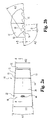
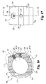
- Implant 10 includes an upper bone engaging surface 12, a lower bone engaging surface 14, and a central opening 16 extending from upper surface 12 to lower surface 14. While it is contemplated that implant 10 may be formed of any suitable bio-compatible material (e.g. steel, titanium, composites, ceramics, zenograft, composite bone material, etc.), in a preferred aspect of the invention, implant 10 is formed of allograft bone. Referring specifically to Fig. 4 , outline 36 represents a typical outline of an allograft ring suitable for use to form an implant according to the present invention. It will be understood that central opening 16 conforms generally to the medullary canal, typically found in an allograft ring.
- Implant 10 includes a pair of opposing side walls 24 and 26 formed in substantial parallel alignment with longitudinal axis 64. A further pair of oblique angled side walls 20 and opposing side wall 28 are formed at an angle A5 with respect to side walls 26 and 24. In a preferred embodiment, angle A5 is approximately 30 degrees.
- implant 10 includes a front face and an opposing end face. Front face 18 extends substantially perpendicular to longitudinal axis 64 and at an angle of A4 with respect to angled surface 20. In a preferred embodiment, angle A4 is substantially 60 degrees. While not required, front face 18 and face 30 are planar surfaces in substantially parallel alignment. Further, front face 18 is substantially perpendicular to end face 30.
- a first opening 40 is formed in implant 10 and is internally threaded to received an externally threaded post. Internally threaded opening 40 extends substantially along longitudinal axis 64 and in substantial alignment with side walls 24 and 26.
- a second bore 42 has an axis 66 extending substantially parallel to axis 64 and spaced at a distance D9 therefrom. Bore 42 is adapted to receive a substantially smooth pin. It will be understood that a pin extending in bore 42 will limit the tendency of implant 10 to rotate as an externally threaded rod is inserted into threaded opening 40. In a preferred aspect, distance D9 is approximately 5mm.
- front face 18 and opposing end face 30 are substantially parallel and spaced by distance D2.
- opposing side walls 24 and 26 are substantially parallel and spaced by a distance of D3.
- Opposing angled walls 20 and 28 are substantially parallel and spaced by a distance D6.
- distances D2, D3, and D6 are approximately equal. Still more preferably, in at least one preferred embodiment adapted for implantation in the lumbar spine, distances D2, D3, and D6 are approximately 26mm.
- an angled driving wall 22 is provided at an approximately 30 degree angle with respect to front wall 18.
- Internally threaded bore 44 extends through angled wall 22 along axis 62.
- Axis 62 is substantially parallel to side walls 20 and 28.
- the multi-faceted implant provides three pairs of substantially parallel side walls.
- a reference point 60 is provided on the drawing as an indication of the starting point of the formation of the various walls of the implant.
- Side wall portions 32 and 34 are not machined, thereby preserving at least a portion of the original configuration of the donor bone. It will be understood that the amount of machining required to form an implant according to the present invention depends in large measure on the configuration of the donor bone available and the dimensions of the implant intended to be manufactured from the available donor bone.
- the maximum outer dimensions of the implant permit the implant to be inserted from a direct anterior approach to the spine, an oblique angle to the spine and, while not specifically shown in the drawings, a lateral approach to the spine.
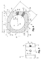
- the implant In one aspect of the invention, intended for use in the lumbar spine, it is preferred that the implant have certain minimal dimensions for the safety and efficacy of the device. While such dimensions are disclosed herein, it is contemplated that dimensions may be altered for various implants in the lumbar, thorasic, and cervical spine without deviating from the present invention provided that the implant provides the desired strength and stability. Specifically, minimum dimensions are given from the surface of the outer side walls to central channel 16. As previously indicated, central channel 16 is preferably defined by the naturally occurring medullary canal.
- Side wall 19 has a dimension D5.
- Side wall 25 has a dimension D7.
- Side wall 31 has a dimension D4.
- Side wall 27 has a dimension D8.
- dimensions D5, D7, and D8 are limited to a minimum thickness of 4mm.
- Dimension D4 may have an even smaller minimum thickness of approximately 3mm.
- implant 10 includes end wall 30 having a height H2 and front wall 18 having a height H1.
- height H1 is substantially greater than height H2.
- opposing bone engaging surfaces 12 and 14 substantially, uniformly taper from height H1 at end wall 30 to height H2 at front wall 18.
- height H1 is approximately 17mm.
- the substantially uniform taper between the upper and lower surfaces 12 and 14 creates an angle A1. In a particular application, angle A1 is approximately 8 degrees.
- upper surface 12 includes buttressed ridges 13 providing an anti-migration surface to engage adjacent vertebral bone upon insertion and limit movement out of the disc space.
- lower bone engaging surface 14 includes a plurality of buttressed bone engaging ridges 15.
- Bone engaging ridges 15 are shown in greater detail in Fig. 2(b) .
- the bone engaging ridges include a leading angled surface 50 and a trailing surface 54 disposed substantially perpendicular to the intervening flat surface 52 disposed between ridges.
- Angled surface 50 is disposed at an angle A3, which in a preferred embodiment is substantially 30 degrees.
- Trailing surface 54 is disposed at an angle A2, which in a preferred embodiment is substantially 90 degrees.
- Individual ridges have a height of approximately H3, which in a preferred embodiment is approximately .5mm. Further, individual ridges are spaced by a distance of approximately 1.5mm, as shown by dimension D1.
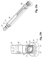
- the present invention further includes an implant inserter, such as that shown in Figs. 5 and 6 .
- Implant inserter 80 includes an outer shaft 82 and an inner shaft 85 rotatably disposed therein.
- Inner shaft 85 includes a thumb wheel 84 connected to its proximal end and an externally threaded portion 90 on the distal end.
- Implant inserter 80 further includes a proximal guide 86, a distal guide 88, and a stop 87.
- the proximal and distal guides are intended to guide and maintain alignment of the inserter within an outer guide sleeve (not shown) while stop 87 provides the function of limiting further movement of the implant inserter into the outer guide sleeve (see Fig. 23a ), thereby limiting the advancement of the implant into the disc space. While the implant inserter is shown with features suitable for use with a guide sleeve, it is contemplated that the inserter may be used without a guide sleeve.
- Distal guide 88 includes upper and lower tapered guiding surfaces 89 and 95, respectively.
- Guide 88 also includes substantially parallel opposed side walls 91 and 93.
- Guide 88 has a width W1 extending between side walls 91 and 93.
- a substantially smooth pin 92 extends from opening 96 while inner shaft 85 extends through opening 94 of guide 88.
- Guide 88 includes a substantially planar bearing wall 98 extending substantially perpendicular to the longitudinal axis of the implant inserter.
- Implant inserter 80 is interconnected with implant 10 by threaded engagement of externally threaded portion 90 of inner shaft 85 with the internally threaded opening 40 of implant 10.
- inner shaft 85 is shown acting as a locking mechanism, it should be understood that other types of generally known locking mechanisms can also be used to secure the implant.
- pin 92 may be inserted into bore 42 to limit rotation of implant 10 while externally threaded portion 90 is threadedly inserted into internally threaded bore 40. Pin 92 also limits rotation of the implant about its own axis as force is applied to advance the implant into the disc space.
- Front face 18 is in substantial abutting engagement with bearing wall 98 such that implant 10 may be impacted into a disc space by forcing bearing wall 98 against front face 18.
- substantially parallel side walls 24 and 26 of the implant are in substantial alignment with side walls 91 and 93 of the implant inserter.
- the width W1 of distal guide 88 is substantially equal to or greater than the width D3 of implant 10.
- the implant inserter Figs. 8 and 9 may be referred to as a straight inserter as it is intended to function in a preferred aspect of the invention from a direct or straight anterior approach to the spine.
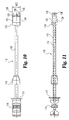
- an oblique inserter is shown in Figs. 10 and 11 .
- the oblique inserter is configured for engaging the implant of Figs. 1-4 to permit insertion from an oblique angle to the spine.
- this approach may be carried out by approaching the disc space in substantial alignment with the axial plane and at an oblique angle with respect to the sagittal plane.
- Oblique inserter 110 includes an outer shaft 112 and an inner shaft 115 movably disposed therein.
- Inner shaft 115 includes a proximal thumb wheel 114 and has a distal end 120 with an external thread pattern.
- Inserter 110 includes proximal guide 116, distal guide 118, and stop 117.
- Distal guide 118 includes opposing tapered surfaces 132 and 134 tapering from opposing upper and lower surfaces 136 and 138, respectively. Distal guide 118 has a maximum width W2 extending from opposing side surfaces 122 and 124.
- the features of implant 110 are substantially similar to the features of implant inserter 180 with the exception of the driving surfaces of distal guide 118.
- distal guide 118 includes a central driving surface 128 substantially perpendicular to longitudinal axis 131 and the planes of side walls 122 and 124. Distal guide 118 further includes a first oblique driving surface 126 disposed at an angle A6 with respect to surface 128. In a preferred aspect, angle A6 is approximately 30 degrees. Distal guide 118 further includes a second angled driving surface 130 disposed at an angle A7 with respect to driving surface 126. In a preferred embodiment, angle A7 is approximately 90 degrees.
- Implant 10 is coupled to implant inserter 110 by engagement of externally threaded portion 120 of the inner shaft with internally threaded opening 44.
- Driving surfaces 126, 128, and 130 of distal guide 118 substantially engage surfaces 26, 22, and 18, respectively, of implant 10. It will be understood that driving surfaces of distal guide 118 are configured to substantially mate with the external surfaces of implant 10 such that force transmitted on the implant inserter tending to urge the implant into the disc space is substantially transmitted to implant 10. Additionally, angled side walls 126 and 130 inhibit rotation of implant 10.
- substantially parallel side walls 20 and 28 of implant 10 are in substantial parallel alignment with opposing parallel side walls 122 and 124 of distal guide 118.
- Width W2 of distal portion 118 is substantially equal to or greater than the width D6 between opposing side walls 20 and 28 of implant 10.
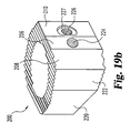
- Implant 200 includes an upper bearing surface 228 and opposing lower bearing surface 230.
- Each of the upper and lower bearing surfaces include anti-migration members.
- the anti-migration members are comprised of buttressed ridges extending substantially perpendicular to side walls 212 and 220.
- upper and lower bearing surfaces 228 and 230 extend at an angle A25 with respect to one another forming a tapered implant. It is contemplated that angle A25 may have a variety of angles, but in a preferred embodiment specifically adapted for establishing and maintaining lumbar lordosis, angle A25 is approximately 8 degrees.
- the implant has a maximum height of H20, which in a preferred aspect is approximately 21mm.
- implant 200 includes two pair of opposing parallel side walls. Specifically, side wall 212 opposes substantially parallel side wall 220. Similarly, angled side walls 214 and opposing angled side wall 222 are in substantially parallel alignment. Side wall 222 extends at an angle A23 with respect to side wall 220. Angled side wall 214 extends at an angle A21 with respect to side wall 212. In a preferred aspect, angles A21 and A23 are substantially identical. Still more preferably, angles A21 and A23 are approximately 30 degrees. Implant 200 further includes end wall 216 and unmachined portion 215 extending between end wall 216 and angled wall 214. A further unmachined portion maintaining substantially the natural shape of donor bone 202 includes wall portion 218 extending between end wall 216 and side wall 220.
- implant 200 includes a short drive wall 206 extending generally perpendicular to longitudinal axis 223.
- An internally threaded opening 224 is formed extending substantially along and in alignment with longitudinal axis 223.
- driving wall 206 may be substantially unmachined and may include arcuate portions such as those found in the naturally occurring outer portion of donor bone 202.
- angled driving walls 210 and 208 extend away from reference line 227 at an angle of A20 and A24, respectively. In a preferred embodiment, angles A20 and A24 are substantially identical. Still more preferably, angles A20 and A24 are substantially 18 degrees.
- Angled driving wall 210 further includes a recess surface 229 extending into surface 210 at an angle of A22.
- angle A22 is approximately 12 degrees, thereby making surface 229 substantially perpendicular to angled side walls 214 and 222.
- an internally threaded bore 226 is defined through the implant extending along axis 231.
- Axis 231 extends in substantial parallel alignment with side walls 214 and 222.
- implant 200 is asymmetrical about axis 231. More specifically, in a preferred aspect of the invention axis 231 is approximately 12mm from angled side wall 214 and approximately 14.5mm from angled side wall 222.
- Implant 200 further includes central opening 204, which as previously described, will typically be defined by the naturally occurring medullary canal formed in the donor bone graft.
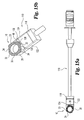
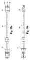
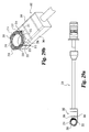
- Implant inserter 250 is substantially identical to the implant inserter of Fig. 5 with the exception of distal guide 252.
- Distal guide 252 includes a first angled drive surface 256 and an opposing angled drive surface 258 separated from the first drive surface by a concave surface 260.
- Surfaces 256 and 258 each extend at an angel A26 with respect to reference line 261 ( Fig. 21(c) ).
- Reference line 261 is substantially perpendicular to the surface of side walls 257 and 259.
- angle A26 is substantially 18 degrees to matingly engage corresponding surfaces on implant 200.
- Distal guide 252 further includes an internal bore 262 extending through surface 260 adapted to receive the inner shaft.
- the inner shaft has an externally threaded portion 254 extending beyond distal guide 252.
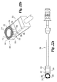
- implant inserter 250 is shown selectively coupled to implant 200.
- Distal guide 252 abuttingly engages implant 200.
- angled drive surfaces 256 and 258 abuttingly engage angled drive surfaces 210 and 208, respectively.
- angled surfaces act to inhibit rotation of implant 200.
- Angled surfaces 256 and 258 limit rotation of the implant about the longitudinal axis of the inserter as the threaded post is engaged to implant 200 and rotation of the implant about itself as force is applied to urge the implant into the disc space.
- the angled drive surfaces provide secure engagement with the implant without the need for additional openings that may weaken the implant walls.
- Concave surface 260 is intended to be spaced from naturally occurring surface 206 such that machining of surface 206 is not required to provide the requisite clearance. Further, by spacing the driving walls from the wall having the threaded opening, force applied to the implant during insertion is concentrated away from the implant opening thereby having less tendency to cause fracture. This may be particularly beneficial where somewhat brittle materials, such as bone or ceramics, are used to form the implant. As shown in Figs. 22(a)-(b) , with implant 200 securely engaged with driver 250, opposing implant side walls 200 and 220 are in substantial alignment with implant driver side walls 257 and 259.
- angled driving surfaces rather than a single planar drive surface, more of the natural architecture of the bone may be maintained, thereby increasing the strength of the implant. While angled drive surfaces are shown as substantially planar surfaces it will be understood that they may also be arcuate, concave, convex, or complex surfaces.
- Implant 200 may be inserted into a vertebral disc space properly prepared for receipt from a direct anterior approach.
- a distraction window 268 is disposed adjacent a vertebral body V1 with distraction extensions 270 and 272 extending into the vertebral disc space (the opposing upper vertebra is not shown).
- Guide tube 262 is selectively coupled to distraction window 268.
- Distraction window and guide tube define a substantially rectangular working channel (not shown) substantially confirming to the dimensions of the distal guide 252. Inserter 250 with selectively coupled implant 200 attached thereto may then be inserted through guide tube 266 and distraction window 268 and guided to the disc space.
- Implant inserter is slidably advanced in the guide tube 266 with distal guide maintaining alignment until stop 271 engages the distal end 273 of guide tube 266. Implant 200 will thereby be positioned in the proper location in the disc space with the intended orientation.
- the thumb wheel of implant inserter 250 may then be rotated to threadedly disengage the inserter from implant 200. Once implant inserter 250 has been disengaged from implant 200.
- the inserter may be removed from the guide tube and distraction window. Guide tube 266 and distraction window 268 may then be removed from the disc space.
- Implant 200 is shown disposed in a prepared end plate of vertebral V1. It will be understood that an opposed vertebra is disposed above the implant creating a disc space, but the upper opposed vertebra has been removed from the illustration for the purpose of clarity. Implant 200 is shown disposed in channel C1 defined in the end plate of vertebra V1. One method of forming channel C1 is disclosed in Provisional Application entitled “ Instruments and Techniques for Disc Space Preparation,” filed on February 22, 2000 . Channel C1 extends in a direction extending from the anterior to the posterior portion of the vertebra and is configured for direct anterior insertion of an implant. End surface 216 is shown in substantial alignment with posterior portion 274 of channel C1.
- end surface 216 is disposed substantially adjacent the posterior portion 275 of vertebra V1.
- Side walls 212 and 220 are disposed laterally with respect to vertebra V1.
- implant 200 is disposed in the disc space between vertebra V1 and the upper opposed vertebra (not shown) such that the taper between opposed bone engaging surfaces 228 and 230 is in proper alignment and orientation to maintain the appropriate angular relationship between the opposing vertebral bodies.
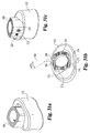
- Inserter 300 adapted for insertion of implant 200 from an anterior-oblique approach to the spine. Inserter 300 includes features also found in implant inserter 250 with the exception that distal guide 302 has been configured to permit engagement with an implant for oblique insertion.
- Distal guide 302 includes a first angled drive surface 310 disposed at an angle A33 with respect to side wall 306. In a preferred embodiment, A33 is approximately 42 degrees.
- a second angled drive surface 314 is disposed at an angle A32 with respect to side wall 308. In the preferred aspect, A32 is approximately 30 degrees.
- a third angled surface 312 is disposed at an angle A30 with respect to angled drive surface 310 and an angle A31 with respect to angled drive surface 314.
- angle A30 is approximately 144 degrees and angle A31 is approximately 108 degrees.
- an internal bore 316 is formed through distal guide 302. Bore 316 is formed a distance D30 from side wall 308 and a distance D31 from side wall 306. In a preferred aspect of the invention, D31 is greater than the distance D30 such that bore 316 is offset with respect to the longitudinal axis of guide 302. More specifically, distance D30 is approximately 12mm and distance D3l is approximately 15mm.
- implant inserter 300 is shown selectively coupled to implant 200.
- Angled driving surfaces 310 and 314 are in abutting engagement with driving surfaces 212 and 208. It will be noted that angled surface 312 and 310 have sufficient length such that side wall 206 is not intended to be in substantial contact with the implant driver. Further, it is contemplated that surface 312 may be spaced slightly from wall 210 to limit stress on the implant adjacent opening 226.
- Implant 200 is aligned with distal guide 302 such that opposing side walls 214 and 222 are in substantial alignment with side walls 308 and 306, respectively, of distal guide 302. Moreover, angled driving surfaces 310 and 314 cooperate to limit implant rotation.
- a distraction window 342 is disposed in a disc space created by vertebra V2 and an opposing upper vertebra (not shown) with distraction extensions 344 and 346 extending into the disc space.
- Distraction window 342 is positioned in the disc space from an anterior-oblique angle approach to the spine.
- reference line 348 represents a direct anterior approach to the spine, in substantial alignment with the sagittal plane.
- distraction window 342 is positioned into the disc space from an angled approach shown by angle A35. In a preferred embodiment, with opposing angled side walls disposed at an approximately 30 degree angle, angle A35 is approximately 30 degrees.
- a guide tube 340 is selectively coupled to distraction window 342, thereby forming a substantially rectangular working channel into the disc space. Inserter 300 with interconnected implant 200 is then inserted through guide sleeve 340 until implant 200 is disposed in the disc space in preformed channel C2.
- the guide sleeve has dimensions substantially corresponding to the implant dimensions, thereby limiting the amount of tissue, vessels and other structures that must be removed or retracted for placement of the implant.
- the inner shaft is then rotated to release implant inserter from implant 200.
- the implant inserter, guide tube, and distraction window may then be removed.
- the orientation of implant 200 in comparison to vertebra V2 is substantially identical to the orientation of implant 200 with respect to vertebra V1 shown in Figs. 24(a)-24(c) .
- End wall 216 is in substantial alignment with posterior portion 274 of channel C2. End wall 216 is disposed substantially adjacent posterior portion 275 of vertebra V2. Further, opposed side walls 212 and 250 are in substantial lateral alignment with the lateral portions of vertebra V2. Thus, it will be understood that implant 200 is positioned in the disc space with the tapering surfaces 228 and 230 extending in the proper orientation to provide maintenance of angulation between vertebra V2 and the opposing upper vertebra (not shown).
- implants described herein may be inserted from a direct lateral approach to the spine.
- the same orientation in the disc space may be achieved regardless of the direction of insertion and the guiding instruments used.
- the present invention provides an implant having multiple facets or substantially parallel side walls allowing uniform orientation of the implant in the disc space although it is inserted by multiple, often guided, approaches to the spine.
- the embodiments of the implants according to the present invention permit insertion from a direct anterior, oblique-anterior and a direct lateral approach to the spine. While preferred embodiments of the invention have disclosed three pair of substantially parallel side walls disposed at a various angles, it is contemplated that more than three pair of substantially parallel side walls could be utilized to provide for implant insertion from a plurality of angles. Further, while a particular angle of 30 degrees has been utilized for the purposes of illustration in a preferred embodiment, it will be understood that any oblique angle might be utilized to provide for insertion from multiple approaches from the spine.
Applications Claiming Priority (3)
| Application Number | Priority Date | Filing Date | Title |
|---|---|---|---|
| US18393000P | 2000-02-22 | 2000-02-22 | |
| US183930P | 2000-02-22 | ||
| PCT/US2001/005638 WO2001062191A2 (en) | 2000-02-22 | 2001-02-22 | Anterior impacted bone graft and driver instruments |
Publications (2)
| Publication Number | Publication Date |
|---|---|
| EP1259198A2 EP1259198A2 (en) | 2002-11-27 |
| EP1259198B1 true EP1259198B1 (en) | 2008-03-26 |
Family
ID=22674883
Family Applications (1)
| Application Number | Title | Priority Date | Filing Date |
|---|---|---|---|
| EP01914433A Expired - Lifetime EP1259198B1 (en) | 2000-02-22 | 2001-02-22 | Spinal implant and insertion tool |
Country Status (9)
| Country | Link |
|---|---|
| US (5) | US6984245B2 (ja) |
| EP (1) | EP1259198B1 (ja) |
| JP (1) | JP4255234B2 (ja) |
| AT (1) | ATE390100T1 (ja) |
| AU (1) | AU774707B2 (ja) |
| CA (1) | CA2395393A1 (ja) |
| DE (1) | DE60133370T2 (ja) |
| ES (1) | ES2302724T3 (ja) |
| WO (1) | WO2001062191A2 (ja) |
Cited By (1)
| Publication number | Priority date | Publication date | Assignee | Title |
|---|---|---|---|---|
| US9011450B2 (en) | 2012-08-08 | 2015-04-21 | DePuy Synthes Products, LLC | Surgical instrument |
Families Citing this family (204)
| Publication number | Priority date | Publication date | Assignee | Title |
|---|---|---|---|---|
| US6086593A (en) | 1998-06-30 | 2000-07-11 | Bonutti; Peter M. | Method and apparatus for use in operating on a bone |
| US6099531A (en) | 1998-08-20 | 2000-08-08 | Bonutti; Peter M. | Changing relationship between bones |
| JP2003530131A (ja) | 1999-03-07 | 2003-10-14 | ディスクレ リミテッド | コンピューターを利用する手術方法及び装置 |
| JP4221159B2 (ja) * | 1999-05-05 | 2009-02-12 | ウォーソー・オーソペディック・インコーポレーテッド | 入れ子状椎体間脊椎固定インプラント |
| EP1259198B1 (en) * | 2000-02-22 | 2008-03-26 | Warsaw Orthopedic, Inc. | Spinal implant and insertion tool |
| US7462195B1 (en) | 2000-04-19 | 2008-12-09 | Warsaw Orthopedic, Inc. | Artificial lumbar interbody spinal implant having an asymmetrical leading end |
| US6350283B1 (en) | 2000-04-19 | 2002-02-26 | Gary K. Michelson | Bone hemi-lumbar interbody spinal implant having an asymmetrical leading end and method of installation thereof |
| WO2001095837A1 (en) * | 2000-06-13 | 2001-12-20 | Michelson Gary K | Manufactured major long bone ring implant shaped to conform to a prepared intervertebral implantation space |
| US6520993B2 (en) | 2000-12-29 | 2003-02-18 | Depuy Acromed, Inc. | Spinal implant |
| US7223291B2 (en) | 2001-07-16 | 2007-05-29 | Spinecore, Inc. | Intervertebral spacer device having engagement hole pairs for manipulation using a surgical tool |
| US8940047B2 (en) | 2001-02-15 | 2015-01-27 | Spinecore, Inc. | Intervertebral spacer device having recessed notch pairs for manipulation using a surgical tool |
| US6989031B2 (en) * | 2001-04-02 | 2006-01-24 | Sdgi Holdings, Inc. | Hemi-interbody spinal implant manufactured from a major long bone ring or a bone composite |
| US6890355B2 (en) * | 2001-04-02 | 2005-05-10 | Gary K. Michelson | Artificial contoured spinal fusion implants made of a material other than bone |
| FR2824261B1 (fr) | 2001-05-04 | 2004-05-28 | Ldr Medical | Prothese de disque intervertebral et procede et outils de mise en place |
| US6558424B2 (en) | 2001-06-28 | 2003-05-06 | Depuy Acromed | Modular anatomic fusion device |
| JP4295086B2 (ja) | 2001-07-11 | 2009-07-15 | ヌバシブ, インコーポレイテッド | 手術の間の神経近接度、神経の方向、および病理学を決定するシステムおよび方法 |
| US8366775B2 (en) * | 2001-07-16 | 2013-02-05 | Spinecore, Inc. | Intervertebral spacer device having an angled perimeter for manipulation using a surgical tool |
| US7635368B2 (en) * | 2001-07-16 | 2009-12-22 | Spinecore, Inc. | Intervertebral spacer device having simultaneously engageable angled perimeters for manipulation using a surgical tool |
| US6585749B2 (en) | 2001-08-01 | 2003-07-01 | Sulzer Spine-Tech Inc. | Surgical implant instrument and method |
| EP2481338A3 (en) | 2001-09-25 | 2012-09-05 | Nuvasive, Inc. | System for performing surgical procedures and assessments |
| US7077864B2 (en) * | 2002-02-12 | 2006-07-18 | Cross Medical Products, Inc. | Vertebral interbody cage with translatable locking screw |
| US6726720B2 (en) | 2002-03-27 | 2004-04-27 | Depuy Spine, Inc. | Modular disc prosthesis |
| US20080027548A9 (en) | 2002-04-12 | 2008-01-31 | Ferree Bret A | Spacerless artificial disc replacements |
| US8038713B2 (en) | 2002-04-23 | 2011-10-18 | Spinecore, Inc. | Two-component artificial disc replacements |
| FR2841124B1 (fr) * | 2002-06-25 | 2007-04-13 | Eurosurgical | Cage intersomatique reversible et son dispositif de mise en place entre le corps vertebraux d'une colonne vertebrale |
| US7582058B1 (en) | 2002-06-26 | 2009-09-01 | Nuvasive, Inc. | Surgical access system and related methods |
| JP4088495B2 (ja) * | 2002-08-20 | 2008-05-21 | 昭和医科工業株式会社 | 椎間ケージ |
| US8137284B2 (en) | 2002-10-08 | 2012-03-20 | Nuvasive, Inc. | Surgical access system and related methods |
| AU2003277287A1 (en) * | 2002-10-08 | 2004-05-04 | Warsaw Orthopedic, Inc. | Insertion device and techniques for orthopaedic implants |
| JP4654125B2 (ja) | 2002-10-29 | 2011-03-16 | スパインコア,インコーポレイテッド | 人工椎間板を植え込む際に使用するための器具類、方法、および機能 |
| WO2004041131A2 (en) * | 2002-10-31 | 2004-05-21 | Spinal Concepts, Inc. | Movable disc implant |
| FR2846550B1 (fr) * | 2002-11-05 | 2006-01-13 | Ldr Medical | Prothese de disque intervertebral |
| US7691057B2 (en) | 2003-01-16 | 2010-04-06 | Nuvasive, Inc. | Surgical access system and related methods |
| US7291173B2 (en) | 2003-05-06 | 2007-11-06 | Aesculap Ii, Inc. | Artificial intervertebral disc |
| US20050143824A1 (en) * | 2003-05-06 | 2005-06-30 | Marc Richelsoph | Artificial intervertebral disc |
| US7105024B2 (en) * | 2003-05-06 | 2006-09-12 | Aesculap Ii, Inc. | Artificial intervertebral disc |
| DE10324108B3 (de) * | 2003-05-21 | 2005-01-27 | Aesculap Ag & Co. Kg | Wirbelkörperersatzimplantat |
| US20050038511A1 (en) * | 2003-08-15 | 2005-02-17 | Martz Erik O. | Transforaminal lumbar interbody fusion (TLIF) implant, surgical procedure and instruments for insertion of spinal implant in a spinal disc space |
| US7905840B2 (en) | 2003-10-17 | 2011-03-15 | Nuvasive, Inc. | Surgical access system and related methods |
| JP4463819B2 (ja) | 2003-09-25 | 2010-05-19 | ヌヴァシヴ インコーポレイテッド | 外科手術接近システム |
| US7041137B2 (en) | 2003-10-07 | 2006-05-09 | Lanx, Llc | Spinal implant |
| DE20315613U1 (de) * | 2003-10-08 | 2003-12-11 | Aesculap Ag & Co. Kg | Zwischenwirbelimplantat |
| DE20315611U1 (de) * | 2003-10-08 | 2003-12-11 | Aesculap Ag & Co. Kg | Zwischenwirbelimplantat |
| FR2861582B1 (fr) * | 2003-10-29 | 2006-02-10 | Eurosurgical | Cage intersomatique pour fusion lombaire par abord transforaminal et son dispositif porte cage |
| US7550010B2 (en) * | 2004-01-09 | 2009-06-23 | Warsaw Orthopedic, Inc. | Spinal arthroplasty device and method |
| US7771479B2 (en) | 2004-01-09 | 2010-08-10 | Warsaw Orthopedic, Inc. | Dual articulating spinal device and method |
| US7625379B2 (en) * | 2004-01-26 | 2009-12-01 | Warsaw Orthopedic, Inc. | Methods and instrumentation for inserting intervertebral grafts and devices |
| FR2865629B1 (fr) | 2004-02-04 | 2007-01-26 | Ldr Medical | Prothese de disque intervertebral |
| ES2547532T3 (es) | 2004-02-04 | 2015-10-07 | Ldr Medical | Prótesis de disco intervertebral |
| US7247169B1 (en) * | 2004-02-23 | 2007-07-24 | Aesculap Implant Systems, Inc. | Kit of spine gauge blocks and a tool assembly |
| US20050209693A1 (en) * | 2004-03-02 | 2005-09-22 | Janzen Lo | Spinal implants |
| US7918891B1 (en) | 2004-03-29 | 2011-04-05 | Nuvasive Inc. | Systems and methods for spinal fusion |
| FR2869528B1 (fr) * | 2004-04-28 | 2007-02-02 | Ldr Medical | Prothese de disque intervertebral |
| DE202004009542U1 (de) * | 2004-06-16 | 2004-08-12 | Aesculap Ag & Co. Kg | Zwischenwirbelimplantat |
| US7776045B2 (en) * | 2004-08-20 | 2010-08-17 | Warsaw Orthopedic, Inc. | Instrumentation and methods for vertebral distraction |
| US7988699B2 (en) * | 2004-10-19 | 2011-08-02 | Warsaw Orthopedic, Inc. | Adjustable instrumentation for spinal implant insertion |
| US8029512B2 (en) * | 2004-10-26 | 2011-10-04 | Pioneer Surgical Technology | Spinal stabilization device and methods |
| US7875080B2 (en) * | 2004-11-10 | 2011-01-25 | Warsaw Orthopedic, Inc. | Intervertebral spacer |
| EP1814474B1 (en) | 2004-11-24 | 2011-09-14 | Samy Abdou | Devices for inter-vertebral orthopedic device placement |
| FR2879436B1 (fr) | 2004-12-22 | 2007-03-09 | Ldr Medical | Prothese de disque intervertebral |
| US7749269B2 (en) | 2005-03-28 | 2010-07-06 | Warsaw Orthopedic, Inc. | Spinal system and method including lateral approach |
| US7763078B2 (en) | 2005-03-28 | 2010-07-27 | Warsaw Orthopedic, Inc. | Spinal device including lateral approach |
| US7942903B2 (en) | 2005-04-12 | 2011-05-17 | Moskowitz Ahmnon D | Bi-directional fixating transvertebral body screws and posterior cervical and lumbar interarticulating joint calibrated stapling devices for spinal fusion |
| US9814601B2 (en) | 2005-04-12 | 2017-11-14 | Nathan C. Moskowitz | Bi-directional fixating/locking transvertebral body screw/intervertebral cage stand-alone constructs |
| US9532821B2 (en) | 2005-04-12 | 2017-01-03 | Nathan C. Moskowitz | Bi-directional fixating/locking transvertebral body screw/intervertebral cage stand-alone constructs with vertical hemi-bracket screw locking mechanism |
| US7846188B2 (en) | 2005-04-12 | 2010-12-07 | Moskowitz Nathan C | Bi-directional fixating transvertebral body screws, zero-profile horizontal intervertebral miniplates, total intervertebral body fusion devices, and posterior motion-calibrating interarticulating joint stapling device for spinal fusion |
| US9744052B2 (en) | 2005-04-12 | 2017-08-29 | Nathan C. Moskowitz | Bi-directional fixating/locking transvertebral body screw/intervertebral cage stand-alone constructs |
| US9848993B2 (en) | 2005-04-12 | 2017-12-26 | Nathan C. Moskowitz | Zero-profile expandable intervertebral spacer devices for distraction and spinal fusion and a universal tool for their placement and expansion |
| US11903849B2 (en) | 2005-04-12 | 2024-02-20 | Moskowitz Family Llc | Intervertebral implant and tool assembly |
| US20060235520A1 (en) * | 2005-04-19 | 2006-10-19 | Pannu Yashdip S | Spinal implant apparatus, method and system |
| US8777959B2 (en) | 2005-05-27 | 2014-07-15 | Spinecore, Inc. | Intervertebral disc and insertion methods therefor |
| FR2887762B1 (fr) | 2005-06-29 | 2007-10-12 | Ldr Medical Soc Par Actions Si | Instrumentation d'insertion de prothese de disque intervertebral entre des vertebres |
| US8623088B1 (en) | 2005-07-15 | 2014-01-07 | Nuvasive, Inc. | Spinal fusion implant and related methods |
| US8147521B1 (en) | 2005-07-20 | 2012-04-03 | Nuvasive, Inc. | Systems and methods for treating spinal deformities |
| US8328851B2 (en) * | 2005-07-28 | 2012-12-11 | Nuvasive, Inc. | Total disc replacement system and related methods |
| FR2891135B1 (fr) | 2005-09-23 | 2008-09-12 | Ldr Medical Sarl | Prothese de disque intervertebral |
| FR2893838B1 (fr) | 2005-11-30 | 2008-08-08 | Ldr Medical Soc Par Actions Si | Prothese de disque intervertebral et instrumentation d'insertion de la prothese entre les vertebres |
| US20070162138A1 (en) * | 2005-12-12 | 2007-07-12 | Sdgi Holdings, Inc. | Vertebral implant and insertion tool |
| US7811326B2 (en) * | 2006-01-30 | 2010-10-12 | Warsaw Orthopedic Inc. | Posterior joint replacement device |
| US7635389B2 (en) * | 2006-01-30 | 2009-12-22 | Warsaw Orthopedic, Inc. | Posterior joint replacement device |
| US8066714B2 (en) | 2006-03-17 | 2011-11-29 | Warsaw Orthopedic Inc. | Instrumentation for distraction and insertion of implants in a spinal disc space |
| US20070270862A1 (en) * | 2006-03-30 | 2007-11-22 | Sdgi Holdings, Inc. | Instruments and methods for preparing an intervertebral space |
| US8066774B2 (en) * | 2006-04-07 | 2011-11-29 | Warsaw Orthopedic, Inc. | Artificial disc implants and associated methods and instrumentation |
| US20070255414A1 (en) * | 2006-05-01 | 2007-11-01 | Sdgi Holdings, Inc. | Intervertebral implants with one or more covers and methods of use |
| US7658766B2 (en) * | 2006-05-01 | 2010-02-09 | Warsaw Orthopedic, Inc. | Intervertebral implants with covered inner chamber and methods of use |
| USD741488S1 (en) | 2006-07-17 | 2015-10-20 | Nuvasive, Inc. | Spinal fusion implant |
| US20080027547A1 (en) * | 2006-07-27 | 2008-01-31 | Warsaw Orthopedic Inc. | Prosthetic device for spinal joint reconstruction |
| US20080045968A1 (en) * | 2006-08-18 | 2008-02-21 | Warsaw Orthopedic, Inc. | Instruments and Methods for Spinal Surgery |
| US8454621B2 (en) * | 2006-09-19 | 2013-06-04 | Warsaw Orthopedic, Inc. | Instruments and methods for spinal implant revision |
| US8465546B2 (en) * | 2007-02-16 | 2013-06-18 | Ldr Medical | Intervertebral disc prosthesis insertion assemblies |
| USD566842S1 (en) * | 2007-02-19 | 2008-04-15 | Zimmer Spine, Inc. | Spinal implant |
| USD595853S1 (en) * | 2007-02-27 | 2009-07-07 | Zimmer Spine, Inc. | Spinal implant |
| US8673005B1 (en) | 2007-03-07 | 2014-03-18 | Nuvasive, Inc. | System and methods for spinal fusion |
| US8864832B2 (en) * | 2007-06-20 | 2014-10-21 | Hh Spinal Llc | Posterior total joint replacement |
| FR2916956B1 (fr) * | 2007-06-08 | 2012-12-14 | Ldr Medical | Cage intersomatique,prothese intervertebrale,dispositif d'ancrage et instrumentation d'implantation |
| US10821003B2 (en) | 2007-06-20 | 2020-11-03 | 3Spline Sezc | Spinal osteotomy |
| USD671645S1 (en) | 2007-09-18 | 2012-11-27 | Nuvasive, Inc. | Intervertebral implant |
| US9101491B2 (en) | 2007-12-28 | 2015-08-11 | Nuvasive, Inc. | Spinal surgical implant and related methods |
| AU2009205679B2 (en) | 2008-01-18 | 2013-12-05 | Spinecore, Inc. | Instruments and methods for inserting artificial intervertebral implants |
| US8088163B1 (en) | 2008-02-06 | 2012-01-03 | Kleiner Jeffrey B | Tools and methods for spinal fusion |
| US20090222011A1 (en) * | 2008-02-28 | 2009-09-03 | Warsaw Orthopedic, Inc. | Targeting surgical instrument for use in spinal disc replacement and methods for use in spinal disc replacement |
| US8083796B1 (en) | 2008-02-29 | 2011-12-27 | Nuvasive, Inc. | Implants and methods for spinal fusion |
| US8216317B2 (en) | 2008-03-31 | 2012-07-10 | Stryker Spine | Spinal implant apparatus and methods |
| EP2271933B1 (en) * | 2008-05-07 | 2012-12-19 | University of Strathclyde | A system and method for cell characterisation |
| US10842645B2 (en) | 2008-08-13 | 2020-11-24 | Smed-Ta/Td, Llc | Orthopaedic implant with porous structural member |
| US9700431B2 (en) | 2008-08-13 | 2017-07-11 | Smed-Ta/Td, Llc | Orthopaedic implant with porous structural member |
| US9616205B2 (en) | 2008-08-13 | 2017-04-11 | Smed-Ta/Td, Llc | Drug delivery implants |
| US9358056B2 (en) | 2008-08-13 | 2016-06-07 | Smed-Ta/Td, Llc | Orthopaedic implant |
| CA2734184C (en) * | 2008-08-13 | 2018-01-16 | Smed-Ta/Td, Llc | Orthopaedic implant with porous structural member |
| US20100042213A1 (en) | 2008-08-13 | 2010-02-18 | Nebosky Paul S | Drug delivery implants |
| US8137405B2 (en) * | 2008-10-08 | 2012-03-20 | K2M, Inc. | Spinal interbody spacer |
| USD853560S1 (en) | 2008-10-09 | 2019-07-09 | Nuvasive, Inc. | Spinal implant insertion device |
| US8147554B2 (en) * | 2008-10-13 | 2012-04-03 | Globus Medical, Inc. | Intervertebral spacer |
| US8545566B2 (en) * | 2008-10-13 | 2013-10-01 | Globus Medical, Inc. | Articulating spacer |
| USD621509S1 (en) | 2008-10-15 | 2010-08-10 | Nuvasive, Inc. | Intervertebral implant |
| US8864654B2 (en) | 2010-04-20 | 2014-10-21 | Jeffrey B. Kleiner | Method and apparatus for performing retro peritoneal dissection |
| US8366748B2 (en) | 2008-12-05 | 2013-02-05 | Kleiner Jeffrey | Apparatus and method of spinal implant and fusion |
| US9717403B2 (en) | 2008-12-05 | 2017-08-01 | Jeffrey B. Kleiner | Method and apparatus for performing retro peritoneal dissection |
| FR2941365B1 (fr) * | 2009-01-27 | 2011-03-18 | Acmel Ind | Outil d'implantation et de fixation d'une cage intervertebrale |
| USD656610S1 (en) | 2009-02-06 | 2012-03-27 | Kleiner Jeffrey B | Spinal distraction instrument |
| US9247943B1 (en) | 2009-02-06 | 2016-02-02 | Kleiner Intellectual Property, Llc | Devices and methods for preparing an intervertebral workspace |
| US20100262245A1 (en) * | 2009-02-18 | 2010-10-14 | Alfaro Arthur A | Intervertebral spacer |
| USD754346S1 (en) | 2009-03-02 | 2016-04-19 | Nuvasive, Inc. | Spinal fusion implant |
| US8870957B2 (en) * | 2009-03-04 | 2014-10-28 | Amendia, Inc. | Implant for mammalian bony segment stabilization |
| US9687357B2 (en) | 2009-03-12 | 2017-06-27 | Nuvasive, Inc. | Vertebral body replacement |
| US9387090B2 (en) | 2009-03-12 | 2016-07-12 | Nuvasive, Inc. | Vertebral body replacement |
| US10842642B2 (en) | 2009-04-16 | 2020-11-24 | Nuvasive, Inc. | Methods and apparatus of performing spine surgery |
| US9351845B1 (en) | 2009-04-16 | 2016-05-31 | Nuvasive, Inc. | Method and apparatus for performing spine surgery |
| US8287597B1 (en) | 2009-04-16 | 2012-10-16 | Nuvasive, Inc. | Method and apparatus for performing spine surgery |
| US8906028B2 (en) | 2009-09-18 | 2014-12-09 | Spinal Surgical Strategies, Llc | Bone graft delivery device and method of using the same |
| US9060877B2 (en) | 2009-09-18 | 2015-06-23 | Spinal Surgical Strategies, Llc | Fusion cage with combined biological delivery system |
| US9186193B2 (en) | 2009-09-18 | 2015-11-17 | Spinal Surgical Strategies, Llc | Fusion cage with combined biological delivery system |
| US9173694B2 (en) | 2009-09-18 | 2015-11-03 | Spinal Surgical Strategies, Llc | Fusion cage with combined biological delivery system |
| US10973656B2 (en) | 2009-09-18 | 2021-04-13 | Spinal Surgical Strategies, Inc. | Bone graft delivery system and method for using same |
| USD723682S1 (en) | 2013-05-03 | 2015-03-03 | Spinal Surgical Strategies, Llc | Bone graft delivery tool |
| US8685031B2 (en) | 2009-09-18 | 2014-04-01 | Spinal Surgical Strategies, Llc | Bone graft delivery system |
| US9629729B2 (en) | 2009-09-18 | 2017-04-25 | Spinal Surgical Strategies, Llc | Biological delivery system with adaptable fusion cage interface |
| USD750249S1 (en) | 2014-10-20 | 2016-02-23 | Spinal Surgical Strategies, Llc | Expandable fusion cage |
| US10245159B1 (en) | 2009-09-18 | 2019-04-02 | Spinal Surgical Strategies, Llc | Bone graft delivery system and method for using same |
| US20170238984A1 (en) | 2009-09-18 | 2017-08-24 | Spinal Surgical Strategies, Llc | Bone graft delivery device with positioning handle |
| USD731063S1 (en) | 2009-10-13 | 2015-06-02 | Nuvasive, Inc. | Spinal fusion implant |
| EP2496162B1 (en) * | 2009-11-05 | 2018-10-31 | K2M, Inc. | Semi-constrained bone screw |
| AU2010314954B2 (en) | 2009-11-09 | 2016-01-07 | Centinel Spine, Llc | Spinal implant configured for lateral insertion |
| JP2013511356A (ja) | 2009-11-20 | 2013-04-04 | ニー・クリエイションズ・リミテッド・ライアビリティ・カンパニー | 関節に可変角度接近するための装置 |
| US8608802B2 (en) | 2009-11-20 | 2013-12-17 | Zimmer Knee Creations, Inc. | Implantable devices for subchondral treatment of joint pain |
| US8951261B2 (en) * | 2009-11-20 | 2015-02-10 | Zimmer Knee Creations, Inc. | Subchondral treatment of joint pain |
| KR20120132469A (ko) | 2009-11-20 | 2012-12-05 | 니 크리에이션스, 엘엘씨 | 관절 치료를 위한 좌표 맵핑 시스템 |
| KR20120112470A (ko) | 2009-11-20 | 2012-10-11 | 니 크리에이션스, 엘엘씨 | 관절 결함을 표적화하기 위한 기기 |
| JP2013511358A (ja) | 2009-11-20 | 2013-04-04 | ニー・クリエイションズ・リミテッド・ライアビリティ・カンパニー | 関節修復のためのナビゲーションおよび位置決め機器 |
| US8821504B2 (en) | 2009-11-20 | 2014-09-02 | Zimmer Knee Creations, Inc. | Method for treating joint pain and associated instruments |
| US8801800B2 (en) | 2009-11-20 | 2014-08-12 | Zimmer Knee Creations, Inc. | Bone-derived implantable devices and tool for subchondral treatment of joint pain |
| US8764806B2 (en) | 2009-12-07 | 2014-07-01 | Samy Abdou | Devices and methods for minimally invasive spinal stabilization and instrumentation |
| US8945227B2 (en) * | 2010-02-01 | 2015-02-03 | X-Spine Systems, Inc. | Spinal implant co-insertion system and method |
| AU2011227293A1 (en) | 2010-03-16 | 2012-11-08 | Pinnacle Spine Group, Llc | Intervertebral implants and graft delivery systems and methods |
| US9375303B1 (en) | 2010-04-15 | 2016-06-28 | Zimmer, Inc. | Methods of ordering and manufacturing orthopedic components |
| US9066814B2 (en) | 2010-08-02 | 2015-06-30 | Ulrich Medical Usa, Inc. | Implant assembly having an angled head |
| US8956415B2 (en) | 2010-08-15 | 2015-02-17 | Warsaw Orthopedic, Inc. | Vertebral implant |
| US8603175B2 (en) | 2010-09-30 | 2013-12-10 | Stryker Spine | Method of inserting surgical implant with guiding rail |
| US8425529B2 (en) | 2010-09-30 | 2013-04-23 | Stryker Spine | Instrument for inserting surgical implant with guiding rail |
| US8858637B2 (en) | 2010-09-30 | 2014-10-14 | Stryker Spine | Surgical implant with guiding rail |
| US8828018B2 (en) | 2010-12-13 | 2014-09-09 | Ashraf A. Ragab | Bone cage placement device |
| US9468535B2 (en) | 2010-12-17 | 2016-10-18 | K2M, Inc. | Interbody spacer |
| US9358122B2 (en) | 2011-01-07 | 2016-06-07 | K2M, Inc. | Interbody spacer |
| WO2012103354A1 (en) * | 2011-01-26 | 2012-08-02 | Del Palma Orthopedics, LLC | Upper extremity fusion devices |
| US9579214B1 (en) | 2011-03-01 | 2017-02-28 | John W. McClellan | Peripheral vertebral body spacer implant and insertion tool |
| US8790406B1 (en) | 2011-04-01 | 2014-07-29 | William D. Smith | Systems and methods for performing spine surgery |
| US9017409B2 (en) | 2011-04-22 | 2015-04-28 | K2M, Inc. | Spinal interbody spacer with semi-constrained screws |
| US8845728B1 (en) | 2011-09-23 | 2014-09-30 | Samy Abdou | Spinal fixation devices and methods of use |
| US9198765B1 (en) | 2011-10-31 | 2015-12-01 | Nuvasive, Inc. | Expandable spinal fusion implants and related methods |
| US9380932B1 (en) | 2011-11-02 | 2016-07-05 | Pinnacle Spine Group, Llc | Retractor devices for minimally invasive access to the spine |
| USD721808S1 (en) | 2011-11-03 | 2015-01-27 | Nuvasive, Inc. | Intervertebral implant |
| USD675320S1 (en) | 2011-11-03 | 2013-01-29 | Nuvasive, Inc. | Intervertebral implant |
| US20130226240A1 (en) | 2012-02-22 | 2013-08-29 | Samy Abdou | Spinous process fixation devices and methods of use |
| US9198767B2 (en) | 2012-08-28 | 2015-12-01 | Samy Abdou | Devices and methods for spinal stabilization and instrumentation |
| US9320617B2 (en) | 2012-10-22 | 2016-04-26 | Cogent Spine, LLC | Devices and methods for spinal stabilization and instrumentation |
| US9707096B2 (en) | 2013-03-14 | 2017-07-18 | K2M, Inc. | Spinal fixation device |
| WO2014159739A1 (en) | 2013-03-14 | 2014-10-02 | Pinnacle Spine Group, Llc | Interbody implants and graft delivery systems |
| FR3003159B1 (fr) | 2013-03-14 | 2015-04-03 | Osd Orthopaedic & Spine Dev | Ancillaire rachidien et son mode d'emploi assurant l'insertion, le positionnement et le guidage d'un implant intersomatique par technique mini invasive |
| US10292832B2 (en) | 2013-03-14 | 2019-05-21 | Ohio State Innovation Foundation | Spinal fixation device |
| US10327910B2 (en) | 2013-03-14 | 2019-06-25 | X-Spine Systems, Inc. | Spinal implant and assembly |
| US10322006B2 (en) * | 2013-03-15 | 2019-06-18 | Globus Medical, Inc. | Interbody standalone intervertebral implant |
| US9918848B2 (en) * | 2013-10-07 | 2018-03-20 | Warsaw Orthopedic, Inc. | Spinal implant system and method |
| USD745159S1 (en) | 2013-10-10 | 2015-12-08 | Nuvasive, Inc. | Intervertebral implant |
| US9364341B2 (en) * | 2014-01-09 | 2016-06-14 | Warsaw Orthopedic, Inc. | Spinal implant system and method |
| US10478313B1 (en) | 2014-01-10 | 2019-11-19 | Nuvasive, Inc. | Spinal fusion implant and related methods |
| US10426630B2 (en) * | 2014-02-12 | 2019-10-01 | K2M, Inc. | Spinal implant |
| USD858769S1 (en) | 2014-11-20 | 2019-09-03 | Nuvasive, Inc. | Intervertebral implant |
| US10624757B2 (en) | 2015-04-09 | 2020-04-21 | Centinel Spine, Llc | Spinal implants configured for tissue sparing angle of insertion and related methods |
| EP3280361B1 (en) * | 2015-04-09 | 2023-03-22 | Centinel Spine, LLC | Spinal implants configured for tissue sparing angle of insertion |
| US9474624B1 (en) * | 2015-04-28 | 2016-10-25 | Aegis Spine, Inc. | Intervertebral fusion cage |
| US10327908B2 (en) | 2015-09-18 | 2019-06-25 | K2M, Inc. | Corpectomy device and methods of use thereof |
| US10857003B1 (en) | 2015-10-14 | 2020-12-08 | Samy Abdou | Devices and methods for vertebral stabilization |
| USD797290S1 (en) | 2015-10-19 | 2017-09-12 | Spinal Surgical Strategies, Llc | Bone graft delivery tool |
| US10470900B2 (en) * | 2016-06-17 | 2019-11-12 | Paragon 28, Inc. | Implants, devices, systems, kits and methods of implanting |
| US10744000B1 (en) | 2016-10-25 | 2020-08-18 | Samy Abdou | Devices and methods for vertebral bone realignment |
| US10973648B1 (en) | 2016-10-25 | 2021-04-13 | Samy Abdou | Devices and methods for vertebral bone realignment |
| WO2019013558A1 (ko) * | 2017-07-13 | 2019-01-17 | (주)엘앤케이바이오메드 | 사측방 척추 유합 케이지 |
| AU2018327353A1 (en) | 2017-09-08 | 2020-03-19 | Pioneer Surgical Technology, Inc. | Intervertebral implants, instruments, and methods |
| USD907771S1 (en) | 2017-10-09 | 2021-01-12 | Pioneer Surgical Technology, Inc. | Intervertebral implant |
| US11179248B2 (en) | 2018-10-02 | 2021-11-23 | Samy Abdou | Devices and methods for spinal implantation |
| US11432829B2 (en) | 2019-02-24 | 2022-09-06 | Blue Sky Technologies, LLC | Implant for bone |
| US11596445B2 (en) | 2019-02-24 | 2023-03-07 | Blue Sky Technologies, LLC | Implant for bone |
| US11020236B2 (en) * | 2019-07-27 | 2021-06-01 | T. S. Shanks, PLLC | Spinal implant |
| US11351036B1 (en) | 2021-05-27 | 2022-06-07 | T.S. Shanks PLLC | Spinal implant |
Family Cites Families (36)
| Publication number | Priority date | Publication date | Assignee | Title |
|---|---|---|---|---|
| US985269A (en) * | 1910-03-30 | 1911-02-28 | Vincent Mcintyre | Bolt and nut. |
| US4165746A (en) * | 1977-06-30 | 1979-08-28 | Burgin Kermit H | Plastic forceps |
| US4714469A (en) * | 1987-02-26 | 1987-12-22 | Pfizer Hospital Products Group, Inc. | Spinal implant |
| DE3809793A1 (de) * | 1988-03-23 | 1989-10-05 | Link Waldemar Gmbh Co | Chirurgischer instrumentensatz |
| US6120502A (en) | 1988-06-13 | 2000-09-19 | Michelson; Gary Karlin | Apparatus and method for the delivery of electrical current for interbody spinal arthrodesis |
| US5609635A (en) | 1988-06-28 | 1997-03-11 | Michelson; Gary K. | Lordotic interbody spinal fusion implants |
| CA1333209C (en) * | 1988-06-28 | 1994-11-29 | Gary Karlin Michelson | Artificial spinal fusion implants |
| US5088472A (en) * | 1990-04-04 | 1992-02-18 | Mehdi Fakhrai | Retractor |
| US5192327A (en) * | 1991-03-22 | 1993-03-09 | Brantigan John W | Surgical prosthetic implant for vertebrae |
| ATE282366T1 (de) * | 1993-06-10 | 2004-12-15 | Karlin Technology Inc | Wirbeldistraktor |
| US5397364A (en) * | 1993-10-12 | 1995-03-14 | Danek Medical, Inc. | Anterior interbody fusion device |
| US5885299A (en) * | 1994-09-15 | 1999-03-23 | Surgical Dynamics, Inc. | Apparatus and method for implant insertion |
| US5782919A (en) * | 1995-03-27 | 1998-07-21 | Sdgi Holdings, Inc. | Interbody fusion device and method for restoration of normal spinal anatomy |
| US5683391A (en) * | 1995-06-07 | 1997-11-04 | Danek Medical, Inc. | Anterior spinal instrumentation and method for implantation and revision |
| KR100415064B1 (ko) * | 1995-10-20 | 2005-04-06 | 신테스 아게 츄어 | 추골간임플랜트 |
| CA2199462C (en) * | 1996-03-14 | 2006-01-03 | Charles J. Winslow | Method and instrumentation for implant insertion |
| US5895426A (en) * | 1996-09-06 | 1999-04-20 | Osteotech, Inc. | Fusion implant device and method of use |
| WO1998017207A1 (en) * | 1996-10-21 | 1998-04-30 | Synthes Ag Chur | Surgical prosthetic device |
| US6902566B2 (en) * | 1997-01-02 | 2005-06-07 | St. Francis Medical Technologies, Inc. | Spinal implants, insertion instruments, and methods of use |
| WO1998042269A1 (en) * | 1997-03-24 | 1998-10-01 | Haider Thomas T | Spinal immobilization device and method |
| FR2762778B1 (fr) * | 1997-05-02 | 1999-07-16 | Stryker France Sa | Implant notamment pour le remplacement d'un corps vertebral en chirurgie du rachis |
| US7048762B1 (en) * | 1997-08-27 | 2006-05-23 | Regeneration Technologies, Inc. | Elongated cortical bone implant |
| WO1999009914A1 (en) * | 1997-08-27 | 1999-03-04 | University Of Florida Tissue Bank, Inc. | Cortical bone cervical smith-robinson fusion implant |
| US6482233B1 (en) * | 1998-01-29 | 2002-11-19 | Synthes(U.S.A.) | Prosthetic interbody spacer |
| US6159211A (en) * | 1998-10-22 | 2000-12-12 | Depuy Acromed, Inc. | Stackable cage system for corpectomy/vertebrectomy |
| US6174311B1 (en) * | 1998-10-28 | 2001-01-16 | Sdgi Holdings, Inc. | Interbody fusion grafts and instrumentation |
| US6200347B1 (en) * | 1999-01-05 | 2001-03-13 | Lifenet | Composite bone graft, method of making and using same |
| WO2000066045A1 (en) * | 1999-05-05 | 2000-11-09 | Michelson Gary K | Spinal fusion implants with opposed locking screws |
| US6277149B1 (en) * | 1999-06-08 | 2001-08-21 | Osteotech, Inc. | Ramp-shaped intervertebral implant |
| US6283966B1 (en) * | 1999-07-07 | 2001-09-04 | Sulzer Spine-Tech Inc. | Spinal surgery tools and positioning method |
| US6524318B1 (en) * | 1999-10-18 | 2003-02-25 | Sulzer Spine-Tech Inc. | Spinal surgery instruments and methods |
| US6319257B1 (en) * | 1999-12-20 | 2001-11-20 | Kinamed, Inc. | Inserter assembly |
| EP1259198B1 (en) * | 2000-02-22 | 2008-03-26 | Warsaw Orthopedic, Inc. | Spinal implant and insertion tool |
| WO2002034172A1 (en) * | 2000-10-24 | 2002-05-02 | Sdgi Holdings, Inc. | Osteogenic packing device and method |
| US7169182B2 (en) * | 2001-07-16 | 2007-01-30 | Spinecore, Inc. | Implanting an artificial intervertebral disc |
| US6719794B2 (en) * | 2001-05-03 | 2004-04-13 | Synthes (U.S.A.) | Intervertebral implant for transforaminal posterior lumbar interbody fusion procedure |
-
2001
- 2001-02-22 EP EP01914433A patent/EP1259198B1/en not_active Expired - Lifetime
- 2001-02-22 ES ES01914433T patent/ES2302724T3/es not_active Expired - Lifetime
- 2001-02-22 CA CA002395393A patent/CA2395393A1/en not_active Abandoned
- 2001-02-22 AU AU39822/01A patent/AU774707B2/en not_active Ceased
- 2001-02-22 AT AT01914433T patent/ATE390100T1/de not_active IP Right Cessation
- 2001-02-22 WO PCT/US2001/005638 patent/WO2001062191A2/en active IP Right Grant
- 2001-02-22 JP JP2001561261A patent/JP4255234B2/ja not_active Expired - Fee Related
- 2001-02-22 DE DE60133370T patent/DE60133370T2/de not_active Expired - Fee Related
-
2002
- 2002-08-06 US US10/213,328 patent/US6984245B2/en not_active Expired - Lifetime
-
2005
- 2005-01-05 US US11/030,459 patent/US20050119753A1/en not_active Abandoned
-
2006
- 2006-05-19 US US11/437,392 patent/US7635371B2/en not_active Expired - Fee Related
-
2009
- 2009-12-01 US US12/592,698 patent/US8092537B2/en not_active Expired - Fee Related
-
2011
- 2011-12-06 US US13/311,753 patent/US20120083890A1/en not_active Abandoned
Cited By (1)
| Publication number | Priority date | Publication date | Assignee | Title |
|---|---|---|---|---|
| US9011450B2 (en) | 2012-08-08 | 2015-04-21 | DePuy Synthes Products, LLC | Surgical instrument |
Also Published As
| Publication number | Publication date |
|---|---|
| US20030130737A1 (en) | 2003-07-10 |
| AU3982201A (en) | 2001-09-03 |
| WO2001062191B1 (en) | 2002-03-21 |
| US8092537B2 (en) | 2012-01-10 |
| WO2001062191A3 (en) | 2002-02-07 |
| DE60133370T2 (de) | 2009-04-02 |
| ATE390100T1 (de) | 2008-04-15 |
| WO2001062191A2 (en) | 2001-08-30 |
| US7635371B2 (en) | 2009-12-22 |
| US20100087875A1 (en) | 2010-04-08 |
| CA2395393A1 (en) | 2001-08-30 |
| JP4255234B2 (ja) | 2009-04-15 |
| AU774707B2 (en) | 2004-07-08 |
| US20120083890A1 (en) | 2012-04-05 |
| US20060212120A1 (en) | 2006-09-21 |
| ES2302724T3 (es) | 2008-08-01 |
| DE60133370D1 (ja) | 2008-05-08 |
| US20050119753A1 (en) | 2005-06-02 |
| JP2003523263A (ja) | 2003-08-05 |
| EP1259198A2 (en) | 2002-11-27 |
| US6984245B2 (en) | 2006-01-10 |
Similar Documents
| Publication | Publication Date | Title |
|---|---|---|
| EP1259198B1 (en) | Spinal implant and insertion tool | |
| US11696837B2 (en) | Intervertebral implant with fixation geometry | |
| US11690728B2 (en) | Intervertebral implant with keel | |
| EP2442756B1 (en) | Intervertebral implant | |
| EP1617793B1 (en) | Interbody fusion device | |
| US9668882B2 (en) | Biomedical implant inserters and related apparatus, systems, and methods | |
| AU2004202053B2 (en) | Anterior impacted bone graft and driver instruments | |
| EP3162324B1 (en) | Cervical disc and instrumentation | |
| WO2014124327A1 (en) | Biomedical, implant inserters and related apparatus, systems, and methods |
Legal Events
| Date | Code | Title | Description |
|---|---|---|---|
| PUAI | Public reference made under article 153(3) epc to a published international application that has entered the european phase |
Free format text: ORIGINAL CODE: 0009012 |
|
| 17P | Request for examination filed |
Effective date: 20020919 |
|
| AK | Designated contracting states |
Kind code of ref document: A2 Designated state(s): AT BE CH CY DE DK ES FI FR GB GR IE IT LI LU MC NL PT SE TR |
|
| AX | Request for extension of the european patent |
Free format text: AL;LT;LV;MK;RO;SI |
|
| 17Q | First examination report despatched |
Effective date: 20060808 |
|
| RAP1 | Party data changed (applicant data changed or rights of an application transferred) |
Owner name: WARSAW ORTHOPEDIC, INC. |
|
| GRAP | Despatch of communication of intention to grant a patent |
Free format text: ORIGINAL CODE: EPIDOSNIGR1 |
|
| RTI1 | Title (correction) |
Free format text: SPINAL IMPLANT AND INSERTION TOOL |
|
| GRAS | Grant fee paid |
Free format text: ORIGINAL CODE: EPIDOSNIGR3 |
|
| GRAA | (expected) grant |
Free format text: ORIGINAL CODE: 0009210 |
|
| AK | Designated contracting states |
Kind code of ref document: B1 Designated state(s): AT BE CH CY DE DK ES FI FR GB GR IE IT LI LU MC NL PT SE TR |
|
| REG | Reference to a national code |
Ref country code: GB Ref legal event code: FG4D |
|
| REG | Reference to a national code |
Ref country code: IE Ref legal event code: FG4D Ref country code: CH Ref legal event code: EP |
|
| REF | Corresponds to: |
Ref document number: 60133370 Country of ref document: DE Date of ref document: 20080508 Kind code of ref document: P |
|
| REG | Reference to a national code |
Ref country code: CH Ref legal event code: NV Representative=s name: BOHEST AG |
|
| PG25 | Lapsed in a contracting state [announced via postgrant information from national office to epo] |
Ref country code: FI Free format text: LAPSE BECAUSE OF FAILURE TO SUBMIT A TRANSLATION OF THE DESCRIPTION OR TO PAY THE FEE WITHIN THE PRESCRIBED TIME-LIMIT Effective date: 20080326 |
|
| REG | Reference to a national code |
Ref country code: ES Ref legal event code: FG2A Ref document number: 2302724 Country of ref document: ES Kind code of ref document: T3 |
|
| PG25 | Lapsed in a contracting state [announced via postgrant information from national office to epo] |
Ref country code: AT Free format text: LAPSE BECAUSE OF FAILURE TO SUBMIT A TRANSLATION OF THE DESCRIPTION OR TO PAY THE FEE WITHIN THE PRESCRIBED TIME-LIMIT Effective date: 20080326 |
|
| NLV1 | Nl: lapsed or annulled due to failure to fulfill the requirements of art. 29p and 29m of the patents act | ||
| PG25 | Lapsed in a contracting state [announced via postgrant information from national office to epo] |
Ref country code: BE Free format text: LAPSE BECAUSE OF FAILURE TO SUBMIT A TRANSLATION OF THE DESCRIPTION OR TO PAY THE FEE WITHIN THE PRESCRIBED TIME-LIMIT Effective date: 20080326 |
|
| PG25 | Lapsed in a contracting state [announced via postgrant information from national office to epo] |
Ref country code: SE Free format text: LAPSE BECAUSE OF FAILURE TO SUBMIT A TRANSLATION OF THE DESCRIPTION OR TO PAY THE FEE WITHIN THE PRESCRIBED TIME-LIMIT Effective date: 20080626 Ref country code: PT Free format text: LAPSE BECAUSE OF FAILURE TO SUBMIT A TRANSLATION OF THE DESCRIPTION OR TO PAY THE FEE WITHIN THE PRESCRIBED TIME-LIMIT Effective date: 20080901 |
|
| PG25 | Lapsed in a contracting state [announced via postgrant information from national office to epo] |
Ref country code: NL Free format text: LAPSE BECAUSE OF FAILURE TO SUBMIT A TRANSLATION OF THE DESCRIPTION OR TO PAY THE FEE WITHIN THE PRESCRIBED TIME-LIMIT Effective date: 20080326 |
|
| ET | Fr: translation filed | ||
| PG25 | Lapsed in a contracting state [announced via postgrant information from national office to epo] |
Ref country code: DK Free format text: LAPSE BECAUSE OF FAILURE TO SUBMIT A TRANSLATION OF THE DESCRIPTION OR TO PAY THE FEE WITHIN THE PRESCRIBED TIME-LIMIT Effective date: 20080326 |
|
| PLBE | No opposition filed within time limit |
Free format text: ORIGINAL CODE: 0009261 |
|
| STAA | Information on the status of an ep patent application or granted ep patent |
Free format text: STATUS: NO OPPOSITION FILED WITHIN TIME LIMIT |
|
| 26N | No opposition filed |
Effective date: 20081230 |
|
| PG25 | Lapsed in a contracting state [announced via postgrant information from national office to epo] |
Ref country code: IT Free format text: LAPSE BECAUSE OF FAILURE TO SUBMIT A TRANSLATION OF THE DESCRIPTION OR TO PAY THE FEE WITHIN THE PRESCRIBED TIME-LIMIT Effective date: 20080326 |
|
| PG25 | Lapsed in a contracting state [announced via postgrant information from national office to epo] |
Ref country code: CY Free format text: LAPSE BECAUSE OF FAILURE TO SUBMIT A TRANSLATION OF THE DESCRIPTION OR TO PAY THE FEE WITHIN THE PRESCRIBED TIME-LIMIT Effective date: 20080326 Ref country code: MC Free format text: LAPSE BECAUSE OF NON-PAYMENT OF DUE FEES Effective date: 20090228 |
|
| REG | Reference to a national code |
Ref country code: CH Ref legal event code: PL |
|
| GBPC | Gb: european patent ceased through non-payment of renewal fee |
Effective date: 20090222 |
|
| PG25 | Lapsed in a contracting state [announced via postgrant information from national office to epo] |
Ref country code: CH Free format text: LAPSE BECAUSE OF NON-PAYMENT OF DUE FEES Effective date: 20090228 Ref country code: LI Free format text: LAPSE BECAUSE OF NON-PAYMENT OF DUE FEES Effective date: 20090228 |
|
| REG | Reference to a national code |
Ref country code: FR Ref legal event code: ST Effective date: 20091030 |
|
| PG25 | Lapsed in a contracting state [announced via postgrant information from national office to epo] |
Ref country code: IE Free format text: LAPSE BECAUSE OF NON-PAYMENT OF DUE FEES Effective date: 20090223 Ref country code: DE Free format text: LAPSE BECAUSE OF NON-PAYMENT OF DUE FEES Effective date: 20090901 |
|
| REG | Reference to a national code |
Ref country code: ES Ref legal event code: FD2A Effective date: 20090223 |
|
| PG25 | Lapsed in a contracting state [announced via postgrant information from national office to epo] |
Ref country code: FR Free format text: LAPSE BECAUSE OF NON-PAYMENT OF DUE FEES Effective date: 20090302 Ref country code: GB Free format text: LAPSE BECAUSE OF NON-PAYMENT OF DUE FEES Effective date: 20090222 |
|
| PG25 | Lapsed in a contracting state [announced via postgrant information from national office to epo] |
Ref country code: ES Free format text: LAPSE BECAUSE OF NON-PAYMENT OF DUE FEES Effective date: 20090223 |
|
| PG25 | Lapsed in a contracting state [announced via postgrant information from national office to epo] |
Ref country code: GR Free format text: LAPSE BECAUSE OF FAILURE TO SUBMIT A TRANSLATION OF THE DESCRIPTION OR TO PAY THE FEE WITHIN THE PRESCRIBED TIME-LIMIT Effective date: 20080627 |
|
| PG25 | Lapsed in a contracting state [announced via postgrant information from national office to epo] |
Ref country code: LU Free format text: LAPSE BECAUSE OF NON-PAYMENT OF DUE FEES Effective date: 20090222 |
|
| PG25 | Lapsed in a contracting state [announced via postgrant information from national office to epo] |
Ref country code: TR Free format text: LAPSE BECAUSE OF FAILURE TO SUBMIT A TRANSLATION OF THE DESCRIPTION OR TO PAY THE FEE WITHIN THE PRESCRIBED TIME-LIMIT Effective date: 20080326 |