EP1258638B1 - Aufnahmeelement und Gegenstand mit Aufnahmeelement - Google Patents
Aufnahmeelement und Gegenstand mit Aufnahmeelement Download PDFInfo
- Publication number
- EP1258638B1 EP1258638B1 EP02003244A EP02003244A EP1258638B1 EP 1258638 B1 EP1258638 B1 EP 1258638B1 EP 02003244 A EP02003244 A EP 02003244A EP 02003244 A EP02003244 A EP 02003244A EP 1258638 B1 EP1258638 B1 EP 1258638B1
- Authority
- EP
- European Patent Office
- Prior art keywords
- receptacle element
- receiving element
- holder
- article
- ceramic
- Prior art date
- Legal status (The legal status is an assumption and is not a legal conclusion. Google has not performed a legal analysis and makes no representation as to the accuracy of the status listed.)
- Expired - Lifetime
Links
- 229910010293 ceramic material Inorganic materials 0.000 claims description 4
- 239000000919 ceramic Substances 0.000 description 15
- 230000007797 corrosion Effects 0.000 description 4
- 238000005260 corrosion Methods 0.000 description 4
- 239000000463 material Substances 0.000 description 2
- 239000002184 metal Substances 0.000 description 2
- 230000007935 neutral effect Effects 0.000 description 2
- 239000000126 substance Substances 0.000 description 2
- 238000006243 chemical reaction Methods 0.000 description 1
- 230000002349 favourable effect Effects 0.000 description 1
- 239000003292 glue Substances 0.000 description 1
- 230000005484 gravity Effects 0.000 description 1
- 238000010438 heat treatment Methods 0.000 description 1
- 230000001771 impaired effect Effects 0.000 description 1
- 239000013585 weight reducing agent Substances 0.000 description 1
Images
Classifications
-
- F—MECHANICAL ENGINEERING; LIGHTING; HEATING; WEAPONS; BLASTING
- F16—ENGINEERING ELEMENTS AND UNITS; GENERAL MEASURES FOR PRODUCING AND MAINTAINING EFFECTIVE FUNCTIONING OF MACHINES OR INSTALLATIONS; THERMAL INSULATION IN GENERAL
- F16B—DEVICES FOR FASTENING OR SECURING CONSTRUCTIONAL ELEMENTS OR MACHINE PARTS TOGETHER, e.g. NAILS, BOLTS, CIRCLIPS, CLAMPS, CLIPS OR WEDGES; JOINTS OR JOINTING
- F16B2/00—Friction-grip releasable fastenings
- F16B2/02—Clamps, i.e. with gripping action effected by positive means other than the inherent resistance to deformation of the material of the fastening
-
- F—MECHANICAL ENGINEERING; LIGHTING; HEATING; WEAPONS; BLASTING
- F16—ENGINEERING ELEMENTS AND UNITS; GENERAL MEASURES FOR PRODUCING AND MAINTAINING EFFECTIVE FUNCTIONING OF MACHINES OR INSTALLATIONS; THERMAL INSULATION IN GENERAL
- F16B—DEVICES FOR FASTENING OR SECURING CONSTRUCTIONAL ELEMENTS OR MACHINE PARTS TOGETHER, e.g. NAILS, BOLTS, CIRCLIPS, CLAMPS, CLIPS OR WEDGES; JOINTS OR JOINTING
- F16B2200/00—Constructional details of connections not covered for in other groups of this subclass
- F16B2200/85—Ceramic-to-metal-connections
Definitions
- the invention relates to a fastening device with the features of the preamble of claim 1.
- the fastening means acts between the receiving element and the second article.
- Such receiving elements are known for example in the form of metallic bushings.
- Such bushings form, for example, an intermediate piece between a first article that is made of plastic and a second article that is made of metal, for example.
- Such a receiving element is used for positionally accurate and permanent attachment of the first article of plastic to the second article of metal, for example.
- a holding device in which a ceramic bushing is used. However, it is necessary to fix the ceramic bushing separately in the object receiving it, for which fastening means, e.g. Glue or the like are required.
- fastening means e.g. Glue or the like are required.
- a sleeve-shaped exhaust gas sensor in which a ceramic sleeve is mounted, which encloses a sensor and carries heating wires on the periphery. This ceramic sleeve must be attached separately.
- the present invention is therefore based on the object to propose a receiving element, in which a permanently positionally accurate holding the first article is made possible on a second object, without the receiving element alone requires fastening means.
- the receiving element can be held at least in sections in a form-fitting manner on the first object. It has been shown that ceramic materials behave chemically and electrically neutral with the adjacent materials. In particular, no contact corrosion occurs. Furthermore, ceramic materials can be processed favorably and also have high strength values. Accordingly, with the receiving element according to the invention a permanent positionally accurate attachment of the first object to the second object can be achieved.
- the receiving element is completely made of ceramic.
- Another advantage of the invention is that the specific gravity of ceramic materials is relatively low, whereby a weight reduction over the known prior art is achieved.
- the receiving element is formed like a sleeve with a through hole, wherein the through hole is provided for receiving the fastening means.
- the receiving element can Receiving element molded into the first object or be encapsulated by the first object.
- the fastening means in particular a screw, a rivet, a pin or the like. may be, passes through for attachment of the first article with the second object advantageously the through hole of the receiving element.
- the receiving element or the first object can thus be permanently positioned on the second object in a favorable manner.
- the first object may be a sensor holder, in particular a holder for an engine management sensor.
- Such sensor mounts are regularly made of a plastic, which can be connected via a particular receptacle-like receiving element and a corresponding fastening means with a second object, in particular an engine block.
- Such an article referred to above as the first article, may be coupled to a second article via a ceramic receptacle having chemically and electrically neutral properties be attached.
- the ceramic receiving elements according to the invention can advantageously have the same geometries as known, metallic receiving elements.
- the receiving elements according to the invention can replace known receiving elements.
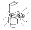
- the figure shows a receiving element according to the invention in the form of a ceramic bushing 10.
- the ceramic bushing 10 is surrounded on its lateral surface by a first object, namely by a plastic bottle 12.
- the plastic bottle 12 is part of a plastic holder 14 which receives a sensor housing 16.
- the lateral surface of the ceramic bushing 10 provides an annular collar 18 over which the ceramic bushing 10 is held positively in the plastic bottle 12.
- the holder 14 to a second, not shown, object, for example, to an engine block, positionally accurate permanently screwed. Due to the electrical and chemical neutrality of the ceramic bushing 10, no contact corrosion can occur between the ceramic bushing 10 and the engine block. Further, no contact corrosion between a screw to be inserted into the through-hole 20 of the ceramic bush 10 and screwed to the second object can take place.
Landscapes
- Engineering & Computer Science (AREA)
- General Engineering & Computer Science (AREA)
- Mechanical Engineering (AREA)
- Bolts, Nuts, And Washers (AREA)
- Connection Of Plates (AREA)
- Measuring Oxygen Concentration In Cells (AREA)
- Measuring Fluid Pressure (AREA)
- Apparatus For Radiation Diagnosis (AREA)
Description
- Die Erfindung betrifft eine Befestigungsvorrichtung mit den Merkmalen des Oberbegriffs des Anspruchs 1.
- Zur Halterung des ersten Gegenstandes an dem zweiten Gegenstand wirkt folglich das Befestigungsmittel zwischen dem Aufnahmeelement und dem zweiten Gegenstand.
- Derartige Aufnahmeelemente sind beispielsweise in Form von metallischen Buchsen bekannt. Derartige Buchsen bilden beispielsweise ein Zwischenstück zwischen einem ersten Gegenstand, der aus Kunststoff ist und einem zweiten Gegenstand, der beispielsweise aus Metall ist. Ein derartiges Aufnahmeelement dient zur positionsgenauen und dauerhaften Befestigung des ersten Gegenstandes aus Kunststoff an dem zweiten Gegenstand aus beispielsweise Metall.
- Bei dem bekannten Stand der Technik hat sich als nachteilig herausgestellt, dass zwischen dem Aufnahmeelement und insbesondere dem mit dem Aufnahmeelement zusammenwirkenden zweiten Gegenstand Nichtverträglichkeiten der Materialpaarungen auftreten können. Insbesondere kann an den Berührungsflächen Kontaktkorrosion auftreten, wodurch eine dauerhaft positionsgenaue Befestigung des ersten Gegenstandes beeinträchtigt werden kann. Entsprechend kann ein Nichtverträglichkeit des Befestigungsmittels mit dem Aufnahmeelement auftreten. Auch hier kann es zu unerwünschten chemischen und elektrischen Reaktionen kommen
- Aus der US-A-5,228,795 ist eine Haltevorrichtung bekannt, bei der eine Keramikbuchse zum Einsatz kommt. Es ist jedoch erforderlich, die Keramikbuchse gesondert in dem sie aufnehmenden Gegenstand zu befestigen ,wofür Befestigungsmittel, z.B. Klebstoff oder dergleichen erforderlich sind. Aus der US-A-3,936,794 ist ein hülsenförmiger Abgassensor bekannt, in welchem eine Keramikhülse gelagert ist, die einen Sensor umschließt und am Umfang Heizdrähte trägt. Auch diese Keramikhülse muss gesondert befestigt werden.
- Der vorliegenden Erfindung liegt deshalb die Aufgabe zugrunde, ein Aufnahmeelement vorzuschlagen, bei dem ein dauerhaft positionsgenaues Haltern des ersten Gegenstandes an einem zweiten Gegenstand ermöglicht wird, ohne dass das Aufnahmeelement für sich alleine Befestigungsmittel bedarf.
- Diese Aufgabe wird mit einer Befestigungsvorrichtung gelöst, die die Merkmale des Anspruchs 1 aufweist.
- Das Aufnahmeelement kann erfindungsgemäß wenigstens abschnittsweise formschlüssig an dem ersten Gegenstand gehaltert sein. Es hat sich gezeigt, dass keramische Werkstoffe sich mit den angrenzenden Materialien chemisch und elektrisch neutral verhalten. Insbesondere tritt keine Kontaktkorrosion auf. Ferner können keramische Werkstoffe günstig verarbeitet werden und weisen zudem hohe Festigkeitswerte auf. Mit dem erfindungsgemäßen Aufnahmeelement kann demnach eine dauerhaft positionsgenaue Befestigung des ersten Gegenstandes an dem zweiten Gegenstand erreicht werden. Vorteilhafterweise ist das Aufnahmeelement vollständig aus Keramik.
- Ein weiterer Vorteil der Erfindung ist, dass das spezifische Gewicht von keramischen Werkstoffen relativ gering ist, wodurch eine Gewichtsreduzierung gegenüber dem bekannten Stand der Technik erzielt wird.
- Erfindungsgemäß kann vorgesehen sein, dass das Aufnahmeelement buchsenartig mit einem Durchgangsloch ausgebildet ist, wobei das Durchgangsloch zur Aufnahme des Befestigungsmittels vorgesehen ist. Insbesondere kann das Aufnahmeelement in den ersten Gegenstand eingeformt bzw. von dem ersten Gegenstand umspritzt sein.
- Das Befestigungsmittel, das insbesondere eine Schraube, ein Niet, ein Stift od.dgl. sein kann, durchgreift zur Befestigung des ersten Gegenstandes mit dem zweiten Gegenstand vorteilhafterweise das Durchgangsloch des Aufnahmeelements. Das Aufnahmeelement bzw. der erste Gegenstand kann damit auf günstige Art und Weise an dem zweiten Gegenstand dauerhaft positioniert werden.
- Erfindungsgemäß ist denkbar, dass der erste Gegenstand eine Sensorhalterung, insbesondere eine Halterung für einen Motormanagementsensor, sein kann. Derartige Sensorhalterungen sind regelmäßig aus einem Kunststoff, die über ein insbesondere buchsenartiges Aufnahmeelement und einem entsprechenden Befestigungsmittel mit einem zweiten Gegenstand, insbesondere einem Motorblock, verbunden werden können.
- Die eingangs genannte Aufgabe wird außerdem durch einen Gegenstand mit einem im Vorhergehenden beschriebenen Aufnahmeelement gelöst. Ein derartiger Gegenstand, im Vorhergehenden als erster Gegenstand bezeichnet, kann über ein keramisches Aufnahmeelement mit chemisch und elektrisch neutralen Eigenschaften an einem zweiten Gegenstand befestigt werden.
- Die erfindungsgemäßen, keramischen Aufnahmeelemente können vorteilhafterweise die gleichen Geometrien wie bekannte, metallische Aufnahmeelementen aufweisen. Damit können die erfindungsgemäßen Aufnahmeelemente bekannte Aufnahmeelemente ersetzen.
- Weitere vorteilhafte Ausgestaltungen und Einzelheiten der Erfindung sind der nachfolgenden Beschreibung zu entnehmen, in der die Erfindung anhand des in der Zeichnung dargestellten Ausführungsbeispiels näher beschrieben und erläutert ist.
- Die Figur zeigt ein erfindungsgemäßes Aufnahmeelement in Form einer Keramikbuchse 10. Die Keramikbuchse 10 wird an ihrer Mantelfläche von einem ersten Gegenstand, nämlich von einer Kunststofflasche 12, umgeben. Die Kunststofflasche 12 ist Bestandeil einer Kunststoffhalterung 14, die ein Sensorgehäuse 16 aufnimmt.
- Die Mantelfläche der Keramikbuchse 10 sieht einen Ringbund 18 vor, über welchen die Keramikbuchse 10 in der Kunststofflasche 12 formschlüssig gehaltert ist.
- Über die Keramikbuchse 10 kann die Halterung 14 an einen zweiten, nicht dargestellten, Gegenstand, beispielsweise an einen Motorblock, positionsgenau dauerhaft angeschraubt werden. Aufgrund der elektrischen und chemischen Neutralität der Keramikbuchse 10 kann zwischen der Keramikbuchse 10 und dem Motorblock keine Kontaktkorrosion auftreten. Ferner kann keine Kontaktkorrosion zwischen einer in das Durchgangsloch 20 der Keramikbuchse 10 einzuführenden Schraube, die mit dem zweiten Gegenstand verschraubt wird, stattfinden.
- Alle in der Beschreibung, den nachfolgenden Ansprüchen und in der Zeichnung dargestellten Merkmale können sowohl einzeln als auch in beliebiger Kombination miteinander erfindungswesentlich sein.
Claims (5)
- Befestigungsvorrichtung mit einem Aufnahmeelement (10) zur Aufnahme eines Befestigungsmittels, wobei das Aufnahmeelement (10) an einem ersten Gegenstand (12) befestigt ist und der erste Gegenstand (12) mit dem Befestigungsmittel über das Aufnahmeelement (10) an einem zweiten Gegenstand befestigbar ist, und dass das Aufnahmeelement (10) aus einem keramischen Werkstoff ist, dadurch gekennzeichnet, dass das Aufnahmeelement (10) an seiner Mantelfläche einen Ringbund (18) vorsieht, über welchen das Aufnahmeelement (10) im ersten Gegenstand (12) wenigstens abschnittsweise formschlüssig gehalten ist.
- Befestigungsvorrichtung nach Anspruch 1, dadurch gekennzeichnet, dass Aufnahmeelement (10) buchsenartig mit einem Durchgangsloch (20) ausgebildet ist, wobei das Durchgangsloch (20) zur Aufnahme des Befestigungsmittels vorgesehen ist.
- Befestigungsvorrichtung nach Anspruch 1 oder 2, dadurch gekennzeichnet, dass das Befestigungsmittel eine Schraube, ein Niet, ein Stift oder dergleichen ist.
- Befestigungsvorrichtung nach einem der vorhergehenden Ansprüche, dadurch gekennzeichnet, dass der erste Gegenstand (12) Teil einer Sensorhalterung (14), insbesondere einer Halterung für einen Motormanagementsensor, ist.
- Befestigungsvorrichtung nach einem der vorhergehenden Ansprüche, dadurch gekennzeichnet, dass der zweite Gegenstand ein Motorblock ist.
Applications Claiming Priority (2)
| Application Number | Priority Date | Filing Date | Title |
|---|---|---|---|
| DE10124473A DE10124473A1 (de) | 2001-05-19 | 2001-05-19 | Aufnahmeelement und Gegenstand mit Aufnahmeelement |
| DE10124473 | 2001-05-19 |
Publications (3)
| Publication Number | Publication Date |
|---|---|
| EP1258638A2 EP1258638A2 (de) | 2002-11-20 |
| EP1258638A3 EP1258638A3 (de) | 2003-07-09 |
| EP1258638B1 true EP1258638B1 (de) | 2006-06-07 |
Family
ID=7685420
Family Applications (1)
| Application Number | Title | Priority Date | Filing Date |
|---|---|---|---|
| EP02003244A Expired - Lifetime EP1258638B1 (de) | 2001-05-19 | 2002-02-21 | Aufnahmeelement und Gegenstand mit Aufnahmeelement |
Country Status (2)
| Country | Link |
|---|---|
| EP (1) | EP1258638B1 (de) |
| DE (2) | DE10124473A1 (de) |
Families Citing this family (4)
| Publication number | Priority date | Publication date | Assignee | Title |
|---|---|---|---|---|
| DE10227986A1 (de) * | 2002-06-22 | 2004-01-08 | Valeo Schalter Und Sensoren Gmbh | Sensor |
| WO2004099722A2 (de) * | 2003-05-12 | 2004-11-18 | Continental Teves Ag & Co. Ohg | Befestigungsmittel für einen sensor oder ein sensorgehäuse |
| DE10352854B4 (de) * | 2003-05-12 | 2020-02-13 | Continental Teves Ag & Co. Ohg | Befestigungsmittel für einen Sensor oder ein Sensorgehäuse |
| DE102005019346A1 (de) * | 2005-04-26 | 2006-05-24 | Daimlerchrysler Ag | Befestigungsvorrichtung eines Sensors |
Family Cites Families (2)
| Publication number | Priority date | Publication date | Assignee | Title |
|---|---|---|---|---|
| US3936794A (en) * | 1974-06-27 | 1976-02-03 | Ford Motor Company | Exhaust gas sensor probe |
| US5228795A (en) * | 1989-12-27 | 1993-07-20 | Rohr, Inc. | Self-tightening fitting for attachment of metal to carbon-carbon structures |
-
2001
- 2001-05-19 DE DE10124473A patent/DE10124473A1/de not_active Ceased
-
2002
- 2002-02-21 EP EP02003244A patent/EP1258638B1/de not_active Expired - Lifetime
- 2002-02-21 DE DE50207062T patent/DE50207062D1/de not_active Expired - Lifetime
Also Published As
| Publication number | Publication date |
|---|---|
| DE10124473A1 (de) | 2002-12-05 |
| EP1258638A2 (de) | 2002-11-20 |
| DE50207062D1 (de) | 2006-07-20 |
| EP1258638A3 (de) | 2003-07-09 |
Similar Documents
| Publication | Publication Date | Title |
|---|---|---|
| EP2301115B1 (de) | Elektrische anschlussvorrichtung | |
| EP0712265B1 (de) | Baugruppe | |
| EP1455160B1 (de) | Metall-Fixiermaterial-Durchführung und Verfahren zur Fertigung eines Grundkörpers einer Metall-Fixiermaterial-Durchführung | |
| DE69013582T2 (de) | Keilförmiger Sockel, befestigt an SPG-Substrat. | |
| DE102007004545A1 (de) | Elektrische Anschlussklemme | |
| DE20314580U1 (de) | Metall-Fixiermaterial-Durchführung | |
| DE102008025428B4 (de) | Verfahren zur Herstellung einer elektrische Anschlusseinrichtung | |
| EP0736429A2 (de) | Hydraulikaggregrat für eine blockiergeschützte Fahrzeugbremsanlage | |
| EP1258638A2 (de) | Aufnahmeelement und Gegenstand mit Aufnahmeelement | |
| EP1403969B1 (de) | Vorrichtung zur Energieversorgung eines Gerätes | |
| DE102006029731B4 (de) | Batterieanschluss | |
| DE102022121391B3 (de) | Grundplatte, spiegelfuss und montageanordnung zur anbringung eines innenspiegels für ein fahrzeug | |
| EP3555471B1 (de) | Aktuator und anschlusselement | |
| DE10010919A1 (de) | Frequenzumrichter | |
| DE60101580T2 (de) | Kohlebürstenhalter | |
| EP2323871B1 (de) | Airbaganordnung | |
| EP2758556B1 (de) | Klemmkörper für einen elektrischen leiter | |
| DE10302793B4 (de) | Sicherung und Sicherungsplatine | |
| DE60104219T2 (de) | Verbinder für ein Kabel und Bausatz für dessen Zusammenbau | |
| DE19928302B4 (de) | Vorrichtung zum Befestigen von Seilzugelementen | |
| DE19827542A1 (de) | Hochtemperaturfeste Kontaktvorrichtung zur Kontaktierung eines planaren Sensorelements | |
| DE10316384A1 (de) | Kontaktadapter für die Kontaktierung einer Antennenstruktur eines Fahrzeuges | |
| EP0203253A2 (de) | Gekapselte unlösbare elektrische Leiterverbindung | |
| EP1318564A1 (de) | Antenne, insbesondere Mobilfunkantenne und/oder Radioantenne, mit einem Verdrehschutz | |
| DE202004021404U1 (de) | Clipartige Kontaktelemente |
Legal Events
| Date | Code | Title | Description |
|---|---|---|---|
| PUAI | Public reference made under article 153(3) epc to a published international application that has entered the european phase |
Free format text: ORIGINAL CODE: 0009012 |
|
| AK | Designated contracting states |
Kind code of ref document: A2 Designated state(s): AT BE CH CY DE DK ES FI FR GB GR IE IT LI LU MC NL PT SE TR |
|
| AX | Request for extension of the european patent |
Free format text: AL;LT;LV;MK;RO;SI |
|
| PUAL | Search report despatched |
Free format text: ORIGINAL CODE: 0009013 |
|
| AK | Designated contracting states |
Designated state(s): AT BE CH CY DE DK ES FI FR GB GR IE IT LI LU MC NL PT SE TR |
|
| AX | Request for extension of the european patent |
Extension state: AL LT LV MK RO SI |
|
| RIC1 | Information provided on ipc code assigned before grant |
Ipc: 7F 16B 2/02 A Ipc: 7F 16B 43/00 B Ipc: 7G 01D 11/30 B |
|
| 17P | Request for examination filed |
Effective date: 20030802 |
|
| RIN1 | Information on inventor provided before grant (corrected) |
Inventor name: ELMERING, KAI Inventor name: NICOLAI, JENS Inventor name: WEHLING, HANS WILHELM |
|
| AKX | Designation fees paid |
Designated state(s): DE ES FR GB IT |
|
| 17Q | First examination report despatched |
Effective date: 20050506 |
|
| GRAP | Despatch of communication of intention to grant a patent |
Free format text: ORIGINAL CODE: EPIDOSNIGR1 |
|
| GRAS | Grant fee paid |
Free format text: ORIGINAL CODE: EPIDOSNIGR3 |
|
| GRAA | (expected) grant |
Free format text: ORIGINAL CODE: 0009210 |
|
| AK | Designated contracting states |
Kind code of ref document: B1 Designated state(s): DE ES FR GB IT |
|
| PG25 | Lapsed in a contracting state [announced via postgrant information from national office to epo] |
Ref country code: IT Free format text: LAPSE BECAUSE OF FAILURE TO SUBMIT A TRANSLATION OF THE DESCRIPTION OR TO PAY THE FEE WITHIN THE PRESCRIBED TIME-LIMIT;WARNING: LAPSES OF ITALIAN PATENTS WITH EFFECTIVE DATE BEFORE 2007 MAY HAVE OCCURRED AT ANY TIME BEFORE 2007. THE CORRECT EFFECTIVE DATE MAY BE DIFFERENT FROM THE ONE RECORDED. Effective date: 20060607 Ref country code: GB Free format text: LAPSE BECAUSE OF FAILURE TO SUBMIT A TRANSLATION OF THE DESCRIPTION OR TO PAY THE FEE WITHIN THE PRESCRIBED TIME-LIMIT Effective date: 20060607 |
|
| REG | Reference to a national code |
Ref country code: GB Ref legal event code: FG4D Free format text: NOT ENGLISH |
|
| REF | Corresponds to: |
Ref document number: 50207062 Country of ref document: DE Date of ref document: 20060720 Kind code of ref document: P |
|
| PG25 | Lapsed in a contracting state [announced via postgrant information from national office to epo] |
Ref country code: ES Free format text: LAPSE BECAUSE OF FAILURE TO SUBMIT A TRANSLATION OF THE DESCRIPTION OR TO PAY THE FEE WITHIN THE PRESCRIBED TIME-LIMIT Effective date: 20060918 |
|
| GBV | Gb: ep patent (uk) treated as always having been void in accordance with gb section 77(7)/1977 [no translation filed] |
Effective date: 20060607 |
|
| ET | Fr: translation filed | ||
| PLBE | No opposition filed within time limit |
Free format text: ORIGINAL CODE: 0009261 |
|
| STAA | Information on the status of an ep patent application or granted ep patent |
Free format text: STATUS: NO OPPOSITION FILED WITHIN TIME LIMIT |
|
| 26N | No opposition filed |
Effective date: 20070308 |
|
| REG | Reference to a national code |
Ref country code: FR Ref legal event code: PLFP Year of fee payment: 15 |
|
| REG | Reference to a national code |
Ref country code: FR Ref legal event code: PLFP Year of fee payment: 16 |
|
| REG | Reference to a national code |
Ref country code: FR Ref legal event code: PLFP Year of fee payment: 17 |
|
| PGFP | Annual fee paid to national office [announced via postgrant information from national office to epo] |
Ref country code: FR Payment date: 20210226 Year of fee payment: 20 |
|
| PGFP | Annual fee paid to national office [announced via postgrant information from national office to epo] |
Ref country code: DE Payment date: 20210209 Year of fee payment: 20 |
|
| PGFP | Annual fee paid to national office [announced via postgrant information from national office to epo] |
Ref country code: IT Payment date: 20210209 Year of fee payment: 20 |
|
| REG | Reference to a national code |
Ref country code: DE Ref legal event code: R071 Ref document number: 50207062 Country of ref document: DE |