EP1258588A2 - Vertically folding gate for garages and the like - Google Patents
Vertically folding gate for garages and the like Download PDFInfo
- Publication number
- EP1258588A2 EP1258588A2 EP02011072A EP02011072A EP1258588A2 EP 1258588 A2 EP1258588 A2 EP 1258588A2 EP 02011072 A EP02011072 A EP 02011072A EP 02011072 A EP02011072 A EP 02011072A EP 1258588 A2 EP1258588 A2 EP 1258588A2
- Authority
- EP
- European Patent Office
- Prior art keywords
- door leaf
- door
- opening
- lintel
- gate
- Prior art date
- Legal status (The legal status is an assumption and is not a legal conclusion. Google has not performed a legal analysis and makes no representation as to the accuracy of the status listed.)
- Withdrawn
Links
Images

Classifications
-
- E—FIXED CONSTRUCTIONS
- E05—LOCKS; KEYS; WINDOW OR DOOR FITTINGS; SAFES
- E05D—HINGES OR SUSPENSION DEVICES FOR DOORS, WINDOWS OR WINGS
- E05D15/00—Suspension arrangements for wings
- E05D15/26—Suspension arrangements for wings for folding wings
- E05D15/262—Suspension arrangements for wings for folding wings folding vertically
-
- E—FIXED CONSTRUCTIONS
- E05—LOCKS; KEYS; WINDOW OR DOOR FITTINGS; SAFES
- E05D—HINGES OR SUSPENSION DEVICES FOR DOORS, WINDOWS OR WINGS
- E05D13/00—Accessories for sliding or lifting wings, e.g. pulleys, safety catches
- E05D13/10—Counterbalance devices
- E05D13/12—Counterbalance devices with springs
- E05D13/1207—Counterbalance devices with springs with tension springs
- E05D13/1215—Counterbalance devices with springs with tension springs specially adapted for overhead wings
-
- E—FIXED CONSTRUCTIONS
- E05—LOCKS; KEYS; WINDOW OR DOOR FITTINGS; SAFES
- E05D—HINGES OR SUSPENSION DEVICES FOR DOORS, WINDOWS OR WINGS
- E05D13/00—Accessories for sliding or lifting wings, e.g. pulleys, safety catches
- E05D13/10—Counterbalance devices
- E05D13/14—Counterbalance devices with weights
- E05D13/145—Counterbalance devices with weights specially adapted for overhead wings
-
- E—FIXED CONSTRUCTIONS
- E05—LOCKS; KEYS; WINDOW OR DOOR FITTINGS; SAFES
- E05F—DEVICES FOR MOVING WINGS INTO OPEN OR CLOSED POSITION; CHECKS FOR WINGS; WING FITTINGS NOT OTHERWISE PROVIDED FOR, CONCERNED WITH THE FUNCTIONING OF THE WING
- E05F15/00—Power-operated mechanisms for wings
- E05F15/60—Power-operated mechanisms for wings using electrical actuators
- E05F15/603—Power-operated mechanisms for wings using electrical actuators using rotary electromotors
- E05F15/605—Power-operated mechanisms for wings using electrical actuators using rotary electromotors for folding wings
-
- E—FIXED CONSTRUCTIONS
- E05—LOCKS; KEYS; WINDOW OR DOOR FITTINGS; SAFES
- E05F—DEVICES FOR MOVING WINGS INTO OPEN OR CLOSED POSITION; CHECKS FOR WINGS; WING FITTINGS NOT OTHERWISE PROVIDED FOR, CONCERNED WITH THE FUNCTIONING OF THE WING
- E05F15/00—Power-operated mechanisms for wings
- E05F15/60—Power-operated mechanisms for wings using electrical actuators
- E05F15/603—Power-operated mechanisms for wings using electrical actuators using rotary electromotors
- E05F15/665—Power-operated mechanisms for wings using electrical actuators using rotary electromotors for vertically-sliding wings
- E05F15/668—Power-operated mechanisms for wings using electrical actuators using rotary electromotors for vertically-sliding wings for overhead wings
- E05F15/681—Power-operated mechanisms for wings using electrical actuators using rotary electromotors for vertically-sliding wings for overhead wings operated by flexible elongated pulling elements, e.g. belts
-
- E—FIXED CONSTRUCTIONS
- E05—LOCKS; KEYS; WINDOW OR DOOR FITTINGS; SAFES
- E05Y—INDEXING SCHEME RELATING TO HINGES OR OTHER SUSPENSION DEVICES FOR DOORS, WINDOWS OR WINGS AND DEVICES FOR MOVING WINGS INTO OPEN OR CLOSED POSITION, CHECKS FOR WINGS AND WING FITTINGS NOT OTHERWISE PROVIDED FOR, CONCERNED WITH THE FUNCTIONING OF THE WING
- E05Y2900/00—Application of doors, windows, wings or fittings thereof
- E05Y2900/10—Application of doors, windows, wings or fittings thereof for buildings or parts thereof
- E05Y2900/106—Application of doors, windows, wings or fittings thereof for buildings or parts thereof for garages
Abstract
Die Erfindung betrifft ein Hubfalttor für Garagen und Hallen mit einem Torblatt, das aus zwei gelenkig miteinander verbundenen, etwa gleichgroßen Torblatthälften besteht, von denen die obere Torblatthälfte 8 an ihrem oberen Rand oberhalb des Torsturzes 13 an einer Sturzzarge 11 schwenkbar gelagert ist und von denen die untere Torblatthälfte 9 an ihrem unteren Rand mit seitlich abstehenden Laufrollen 17 in Laufschienen 18 aus einer Schließstellung, in der die beiden Torblatthälften gegeneinander gefaltet etwa waagerecht abstehen, vertikal bewegbar ist. Ausgleichsgewichte 40 sorgen für einen Gewichtsausgleich beim Öffnen und Schließen des Torblatts 7. Sie hängen an Seilen, die über Seilrollen 46 zum unteren Rand der unteren Torblatthälfte verlaufen. Im Bereich des oberen Randes der oberen Torblatthälfte 8 ist ein elektrischer selbsthemmender Getriebemotor mit mindestens einer Gurtrolle 37 angebracht, auf die mindestens ein Zuggurt 38 auf- und abwickelbar ist, dessen freies Ende zu einer mit dem Schloss 20 in Wirkverbindung stehenden Betätigungsstange 24 führ und beim Anziehen des Zuggurts 38 gegen Federvorspannung gegen einen Anschlag zurückgezogen wird, worauf sich das Torblatt nach oben hin faltend öffnet. Aufgrund der Ausgleichsgewichte und nahe der unteren Torblattunterkante lösbar befestigbaren Tariergewichten 50 lässt sich das Tor auch bei Stromausfall leicht öffnen und schließen. <IMAGE>The invention relates to a foldable gate for garages and halls with a door leaf, which consists of two hingedly connected, approximately equal door leaf halves, of which the upper door leaf half 8 is pivotally mounted at its upper edge above the lintel 13 on a lintel frame 11 and of which lower door leaf half 9 at its lower edge with laterally projecting rollers 17 in rails 18 from a closed position, in which the two door leaf halves protrude folded approximately horizontally, vertically movable. Balance weights 40 ensure a weight balance when opening and closing the door leaf 7. They hang on ropes that run over pulleys 46 to the lower edge of the lower half of the door leaf. In the area of the upper edge of the upper half of the door leaf 8, an electrical self-locking geared motor with at least one belt roller 37 is attached, on which at least one tension belt 38 can be wound and unwound, the free end of which leads to an actuating rod 24 that is operatively connected to the lock 20 and at Tightening the tension belt 38 against spring preload is pulled back against a stop, whereupon the door leaf opens in a folding manner. Due to the counterweights and taring weights 50 that can be releasably attached near the lower bottom edge of the door leaf, the door can be easily opened and closed even in the event of a power failure. <IMAGE>
Description
Die Erfindung betrifft ein motorisch angetriebenes Decken- oder Hubfalttor für Garagen, Hallen und dergl. mit Gewichtsausgleich und motorischem Antrieb für das Öffnen und Schließen und bezieht sich in erster Linie auf das Zusammenwirken des motorischen Antriebs und dessen Hub-Senk- sowie Ver- und Entriegelungsmechanismusses sowohl für den elektrischen Antrieb als auch für den Handbetrieb. In angepasster Form kann das Hubfalttor auch als Hubfensterladen, insbesondere von Schaufenstern oder Einkaufsstätten, eingesetzt werden. Alle diese Ausführungsformen werden nachfolgend kurz Hubfalttor genannt.The invention relates to a motor-driven ceiling or lift folding door for garages, Halls and the like with weight compensation and motor drive for opening and Close and refers primarily to the interaction of the motor drive and its lifting, lowering and locking and unlocking mechanism for both the electric drive as well as for manual operation. In an adapted form it can Folding gate also as a window shutter, especially for shop windows or shops, be used. All of these embodiments are hereinafter referred to as short folding doors called.
Hubfalttore sind für Garagen-, Hallen- und andere Öffnungen in verschiedenen Ausführungsformen bekannt. Bei den meisten Toren oder Fensterverschlussläden sind die beiden Torblatthälften etwa gleich groß (AU-A-18,260/70, US-A-2,393,052, US-A-3,504,249, US-A-4,448,232, DE-C-2 001 349, DE-93 01 447.3 U1). Bei manchen Ausführungsformen ist das untere Torblattteil bis über 50 % größer als das obere (WO 96/12078, US-A-4,026,343, DE-A-1 708 428). Andererseits kann auch das obere Torblattteil etwas höher als der untere ausgebildet sein (US-A-3,224,493). Automatische Ver- oder Entriegelungsmechanismen mit handelsüblichen Torschlösser mit Sicherheitszylindern sind unbekannt. Bekannte Torschlösser werden vielmehr an die speziellen Bedürfnisse angepasst. Bei handbetätigten (Sektional-)Toren mit in die seitlichen Torzargen oder Führungsschienen eingreifenden Verriegelungsgliedern (US-A-1,724,995) ist auf der Drehachse eine Scheibe vorgesehen, an der das Gestänge der Verriegelungsglieder angelenkt ist und somit der Angriff eines von einem motorischen Antrieb bewegten Zuggurts oder anderen Teils nicht möglich ist.Folding gates are available for garage, hall and other openings in various designs known. Most of the gates or window shutters are the two Door leaf halves of approximately the same size (AU-A-18,260 / 70, US-A-2,393,052, US-A-3,504,249, US-A-4,448,232, DE-C-2 001 349, DE-93 01 447.3 U1). In some embodiments the lower door leaf part is up to 50% larger than the upper (WO 96/12078, US-A-4,026,343, DE-A-1 708 428). On the other hand, the upper part of the door leaf can also be slightly higher be formed as the lower one (US-A-3,224,493). Automatic locking or unlocking mechanisms with standard gate locks with security cylinders are unknown. Known gate locks are rather adapted to special needs. at manually operated (sectional) gates with in the side door frames or guide rails engaging locking members (US-A-1,724,995) is a disc on the axis of rotation provided on which the linkage of the locking members is articulated and thus the Do not attack a tension belt or other part that is moved by a motor drive is possible.
Für den Gewichtsausgleich des Tors beim Öffnen und Schließen sind verschiedene Mechanismen bekannt, die entweder Federkonstruktionen vorsehen, wie sie ähnlich bei Deckenschwingtoren verwendet werden. Ferner werden im Bereich des Torsturzes horizontal angebrachte Torsionsfederaufzüge eingesetzt, die über ein Seil am unteren Ende des unteren Torblattteils angreifen, wie es von Sektionaltoren bekannt ist. Ebenso kommen auch nur Ausgleichsgewichte zum Einsatz, die an einem Seil hängen, das über eine Seilrolle im Bereich des Torsturzes zum unteren Teil der unteren Torblatthälfte geführt und dort befestigt ist (DE-A-1 702 428, AU-A-18,260/70, ähnlich WO 96/12078).There are various mechanisms for balancing the weight of the door when opening and closing known that either provide spring structures, as they are similar to overhead swing gates be used. Furthermore, in the area of the lintel are horizontal Attached torsion spring lifts are used, which are attached to a rope at the lower end of the lower Attack the door leaf part, as is known from sectional doors. Likewise come only balance weights are used, which hang on a rope, which over a pulley in the Area of the lintel led to the lower part of the lower half of the door leaf and fastened there (DE-A-1 702 428, AU-A-18,260 / 70, similar to WO 96/12078).
Diesen Toren ist gemein, dass sie die Toröffnung in der Höhe mehr oder minder stark reduzieren, dass teilweise leistungsstarke und somit teure Torantriebe erforderlich sind, dass eine zweiter Garagenzugang oder konstruktiv aufwendige oder komplizierte Ausgleichsmechanismen nötig sind, um auch bei Stromausfall ein manuelles Öffnen und Schließen des Tors, wenigstens von dessen Innenseite, zu ermöglichen, dass, sofern seitliche Ausgleichsgewichte an Seilen vorgesehen sind, unter schwierigen Witterungsverhältnissen, insbesondere Sturm oder Eis und Schnee der Öffnungs- oder Schließvorgang nicht ohne manuelle Hilfe eingeleitet werden kann, und dass eine nachträgliche Montage eines Torantriebs, wenn dieser nicht von vornherein geplant war, kaum möglich ist.What these gates have in common is that they are more or less strong at the height of the gate opening reduce that sometimes powerful and therefore expensive door drives are required, that a second garage access or structurally complex or complicated compensation mechanisms are necessary to open them manually and even in the event of a power failure Closing the gate, at least from the inside, to allow that, if lateral Balance weights are provided on ropes, under difficult weather conditions, in particular storm or ice and snow the opening or closing process can be initiated without manual help, and that a subsequent installation of a Gate drive, if this was not planned from the outset, is hardly possible.
Der Erfindung liegt das technische Problem zugrunde, diese Nachteile teilweise oder insgesamt zu beseitigen und eine betriebssichere, selbsttätige Funktion des Tors zum Öffnen und Schließen zu ermöglichen. Es soll ein kostengünstiger und sicherer elektrisch betätigbarer Elektroantrieb vorgesehen werden können, der auch bei Stromausfall in Verbindung mit dem Gewichtsausgleich eine leichte Handbetätigung von der Außenseite des Tors ermöglicht, der mit einer Ver- und Entriegelung des Tors zusammenwirkt, insbesondere wenn international übliche Torschlösser mit Sicherheits-Schließzylindern verwendet sind und eine oder mehrere gefederte Betätigungsstangen oder Bowdenzüge mit gefederten Verriegelungsgliedern (Schnappverschlüssen) vorgesehen sind, die seitlich an der Torzarge, der Torlaibung oder der Führungsschiene angreifen. Außerdem soll nicht nur bei der elektrischen Betätigung bei allen Betriebsbedingungen ein sicheres selbsttätiges Einleiten des Schließprozesses möglich und gegebenenfalls gesichert sein. Erst nach dem automatischen Entriegeln des Tors ist mit Unterstützung der in oder an den Seitenzargen oder im Raum untergebrachten Torausgleichsgewichte das in der Mitte geteilte Tor motorisch langsam nach oben in die Öffnungsstellung zu ziehen. Allein oder vom Elektromotor mit Getriebesperre soll es in der Öffnungsstellung gehalten werden können. Bei Funkfernsteuerung soll das Schließen des Tores grundsätzlich ohne fremde Hilfe eingeleitet werden. Durch einen guten Gewichtsausgleich soll ein Antriebsmotor von nur geringer Leistung erforderlich sein.The invention is based on the technical problem, some or all of these disadvantages to eliminate and a reliable, automatic function of the gate to open and to allow closing. It is said to be an inexpensive and safe electrically actuable Electric drive can be provided, even in the event of a power failure with the counterbalance enables easy manual operation from the outside of the door, which interacts with locking and unlocking the gate, in particular when international locks with security lock cylinders are used and one or more spring-loaded actuating rods or Bowden cables with spring-loaded Locking elements (snap locks) are provided, which are on the side of the door frame, attack the door reveal or the guide rail. In addition, not only at the electrical actuation ensures safe automatic initiation in all operating conditions the locking process possible and secured if necessary. Only after the automatic Unlocking the gate is with the support of in or on the side frames or in Space-accommodating door counterweights the motor divided in the middle slowly pull up to the open position. Alone or with the electric motor It should be possible to hold the transmission lock in the open position. With radio remote control the closing of the gate should always be initiated without outside help. A good weight balance should make a drive motor of low performance to be required.
Eine Lösung dieses Problems ist mit ihren Ausgestaltungen in den beigefügten Patentansprüchen gekennzeichnet.A solution to this problem is with the forms in the appended claims characterized.
Die Erfindung sieht bei einem nach außen öffnenden Torblatt, d. h. auf der Außenseite der Außenwand neben der Toröffnung angebrachtem Tor, einen am oberen Rand der oberen Torblatthälfte auf der Innenseite angebrachten selbsthemmenden elektrischen Getriebemotor (mit Getriebesperre) vor. Dieser treibt eine Gurtrolle an, deren Zuggurt einerseits an der Rolle und andererseits an einer verschieblichen Bestätigungsstange angreift, die mit der bei allen Toren vorgesehenen, unter Federvorspannung stehenden Schlossstange des üblichen Torschlosses verbunden ist. Bei Einleitung der Öffnungsbewegung werden zunächst die von ihr betätigten Verriegelungsglieder z.B. über Bowdenzüge oder dergl. aus ihrer Verriegelungsstellung zurückgezogen und dann das Tor angehoben. Die mit der hin- und her verschieblichen Schlossstange verbundene hin- und her verschieblichen Betätigungsstange hat, anders als bei bekannten Toren, selbst unmittelbar keine Verriegelungsfunktion mehr. Aufgrund des vorgesehenen Gewichtsausgleichs ist ein leichtgängiges Anheben und - unter Eigengewicht - Absenken des Torblatts aus der Offenstellung in die Schließstellung möglich. Die Steuerung des Motors erfolgt in an sich bekannter Weise, z.B. über einen Taster, ein Schalterschloss oder eine Funksteuerung. Dieser Öffnungs- und Schließprozess ist nur aufgrund des direkten Zusammenwirkens des Gewichtsausgleichs mit Gegengewichten am Torblatt und des an der Betätigungsstange befestigten Zuggurtes, der direkt und nur mit dem Motor zusammenwirkt, möglich. Der Schlossmechanismus umfasst einen in bekannter Weise von Hand betätigbaren, auf die unter Federspannung stehende Schlossstange wirkenden Öffnungsgriff und einen Sicherheitszylinder zum Absperren. Auf diese Weise ist auch bei Stromausfall ein Aufsperren und manuelles Öffnen des Tors möglich. Andererseits braucht keinerlei direkte oder indirekte Schlossbetätigung zum motorischen Öffnen zu erfolgen. Seitlich mit der Torzarge o. dgl. zusammenwirkende Verschlussriegel können über ein Gestänge mit Stangen und (Kipp)Hebeln oder Bowdenzüge betätigt werden und insbesondere im Bereich der Gelenkverbindung der beiden Torhälften in die seitlichen Torzargen einrasten.The invention provides for an outwardly opening door leaf, i. H. on the outside the outer wall next to the gate opening, one at the top of the upper half of the door leaf attached to the inside self-locking electrical Geared motor (with gear lock). This drives a belt reel, the tension belt attacks the roller on the one hand and a movable confirmation rod on the other, those with the spring preload provided for all gates Lock rod of the usual gate lock is connected. When initiating the opening movement the locking elements actuated by it are e.g. about Bowden cables or the like. Retracted from its locked position and then raised the gate. The one that is connected to the lock bar that can be moved back and forth In contrast to known gates, the operating rod itself has a direct effect no more locking function. Due to the intended weight balance, a easy lifting and - under your own weight - lowering the door leaf from the open position possible in the closed position. The motor is controlled in itself known way, e.g. via a button, a switch lock or a radio control. This opening and closing process is only due to the direct interaction of the Weight balance with counterweights on the door leaf and on the operating rod attached tension belt, which interacts directly and only with the motor. The Lock mechanism includes a hand-operated in a known manner on the spring-loaded lock rod opening handle and a security cylinder to shut off. In this way, unlocking is also possible in the event of a power failure and manual opening of the gate possible. On the other hand, it does not need any direct or indirect Lock operated to open the motor. Laterally with the door frame o. The like. Interlocking locking latches can be used with a rod with rods and (Tilt) levers or Bowden cables are operated and especially in the area of the articulated connection snap the two halves of the door into the side door frames.
Bei einem nach innen, z. B. in eine Halle oder Garage, hinein öffnenden Torblatt, ist das Tor innen auf der Innenseite der Außenwand und vor und über der Toröffnung montiert. Der Getriebemotor für das Öffnen des Tors ist in diesem Fall nicht innen auf der oberen Torhälfte, sondern im Bereich des Torsturzes auf der Innenfläche der Außenwand neben der Toröffnung vorgesehen. Der vom Motor angetriebene Zuggurt ist daher auch neben der Toröffnung zu einem Kipphebel geführt, der an der Innenfläche der unteren Torblatthälfte gelagert ist und der an einer mit der Schlossstange verbundenen Betätigungsstange angelenkt ist und seitlich über das Torblatt hinausreicht.With an inside, e.g. B. in a hall or garage, opening door leaf, that is Door installed on the inside of the outer wall and in front of and above the door opening. In this case, the gear motor for opening the gate is not on the inside of the upper one Half of the door, but in the area of the lintel on the inner surface of the outer wall next to the gate opening provided. The pull belt driven by the motor is therefore also next to the gate opening to a rocker arm, which on the inner surface of the lower half of the door leaf is mounted and on an actuating rod connected to the lock rod is articulated and extends laterally beyond the door leaf.
Bei Stromausfall lässt sich auf diese Weise das Tor auch manuell leicht betätigen, weil der Torantrieb von der unteren Torblatthälfte nicht entkoppelt zu werden braucht. Zweckmäßigerweise wird der Gurt beispielsweise im Bereich der Gelenkverbindung der beiden Torblatthälften in eine federnde Öse eingehakt, um beim Öffnen nicht in die geöffnete Toreinfahrt zu hängen.In the event of a power failure, the door can also be easily operated manually because of the Door drive does not need to be decoupled from the lower half of the door leaf. Conveniently, the belt is, for example, in the area of the joint connection of the two door leaf halves hooked into a resilient eyelet so that it does not enter the open gate when opening to hang.
Das Tor kann also vor oder hinter der Toröffnung an der Mauer (Außen- bzw. Innenseite) so angebracht werden, dass es nach außen oder nach innen über dem Torsturz faltet und in dieser Stellung einen spitzen Winkel bildet. Es gibt immer die ganze Toröffnung frei; kein Teil muss in die Toröffnung, z. B. die Durchfahrt, hineinragen.The gate can therefore be in front of or behind the gate opening on the wall (outside or inside) so that it folds outwards or inwards over the lintel and forms an acute angle in this position. The whole gate opening is always free; no part has to be in the gate opening, e.g. B. the passage protrude.
Eine Ausgestaltung des Hubfalttors zur Sicherstellung selbsttätigen Schließens sieht vor, dass an jeder Seite zwei weiche Schraubenfedern vorgesehen sind, die jeweils im Bereich der unteren Torblatthälfte an der Torzarge so angreifen, dass sie das Tor kurz vor Erreichen der Öffnungsstellung entgegen der Öffnungskraft und -bewegung in die Schließstellung zu ziehen versuchen. Die Anbringung sollte somit derart erfolgen, dass diese Gegenkraft erst gegen Ende der Öffnungsbewegung zunehmend erzeugt wird. Dies kann dadurch geschehen, dass das obere Ende jeder Schraubenfeder in einem Laufschlitten befestigt ist, der beim Öffnungsvorgang an oder in der seitlichen Laufschiene des Tors vor Erreichen der Öffnungsstellung gegen einen Anschlag gleitet und die Schraubenfeder beim weiteren Öffnungsvorgang durch die untere Torblatthälfte so spannt, dass sie die Schließbewegung zu Beginn des Schließens zur Überwindung des oberen Totpunkts durch ihr Entspannen zu unterstützen vermag.An embodiment of the fold-up gate to ensure automatic closing provides that two soft coil springs are provided on each side, each in the area the bottom half of the door leaf on the door frame so that they reach the door shortly before the open position against the opening force and movement in the closed position trying to pull. The attachment should therefore be done in such a way that this counterforce is increasingly generated only towards the end of the opening movement. This can be done happen that the top end of each coil spring is fixed in a carriage is in front of the opening process on or in the side track of the door Reaching the open position against a stop slides and the coil spring during the further opening process through the lower half of the door leaf so that it Closing movement at the beginning of the closing to overcome the top dead center can help her relax.
Alternativ zu dieser Ausbildung kann auch im Bereich der die beiden Torblatthälften verbindenden Scharniere oder in diesen eine Spreizfeder vorgesehen sein. Eine Ausführungsform einer solchen Spreizfeder hat zwei unter einem spitzen Winkel stehende Arme, die jeweils an einer Torblatthälfte im Faltknick anliegen. Dieser spitze Winkel ist bei Entspannung größer als der spitze Winkel, den die beiden Torblatthälften in der Schließstellung bilden. Die Spreizfedern kommen somit erst in der letzten Schließphase zur Wirkung und spannen die Torblatthälften im Sinne eines Öffnens auseinander. Sie kommen damit zu Beginn des Schließvorgangs, diesen unterstützend, zur Wirkung.As an alternative to this design, the two door leaf halves can also be connected in the area Hinges or an expansion spring can be provided in these. An embodiment Such a spreading spring has two arms standing at an acute angle, the rest against one half of the door leaf in the fold. This acute angle is when relaxing larger than the acute angle that the two door leaf halves in the closed position form. The spreading springs only come into effect in the last closing phase and stretch the door leaf halves apart in the sense of opening them. You come with it Beginning of the closing process, supporting it, to effect.
Eine weitere Ausgestaltung sieht vor, dass im Bereich der Unterkante der unteren Torblatthälfte mehrere, z. B. acht Tariergewichte zum Austarieren des Torblattgewichts mit Bezug auf die Ausgleichsgewichte angebracht sind. Diese werden zweckmäßigerweise so angebracht, dass sie gegen Lösen oder Herabfallen gesichert sind. Sie können beispielsweise mit einer Mittelbohrung auf Zapfen aufgesteckt werden, die am Ende eine aufschraubbare oder querstellbare Verriegelung haben. Zum Austarieren ist es auch möglich, an den Ausgleichsgewichten Zusatzgewichte, beispielsweise in Form von geschlitzten Scheiben vorzusehen, um seitlich über das Seil auf das Gegengewicht aufgeschoben zu werden, was aber für einen Laien meist unzumutbar ist, vor allem, wenn sich die Ausgleichsgewichte nicht unmittelbar neben der Toröffnung befinden, sondern beispielsweise vor der Garagenrückwand. A further embodiment provides that in the area of the lower edge of the lower half of the door leaf several, e.g. B. eight tare weights for balancing the door leaf weight Regarding the counterweights are attached. These are expediently so attached that they are secured against loosening or falling. For example, you can with a center hole on the pin, which is screwable at the end or have lockable locking. To balance it is also possible additional weights, for example in the form of slotted ones, on the counterweights Provide discs to be pushed laterally over the rope to the counterweight become, which is mostly unreasonable for a layperson, especially if the balance weights not directly next to the gate opening, but for example in front of the back wall of the garage.
Durch Wegnehmen von zwei bis drei der z. B. acht am unteren Rand der unteren Torblatthälfte angebrachten Tariergewichte lässt sich das elektrisch bedienbare Tor mit nur zwei Fingern, auch ohne Motorkraft öffnen und es bleibt in der Offenstellung stehen, weil die Ausgleichsgewichte es dann langsam nach oben in Bewegung setzen, wenn die Torverriegelung von Hand am Torgriff oder mit dem Torschlüssel durch Verschieben der Betätigungsstange mit der Schlossstange gelöst wurde. Führten alle Tariergewichte zu einem Übergewicht gegenüber den Gewichtsausgleichgewichten, so dass das Tor in die Schießstellung nach unten gedrängt ist, so hat die 'Wegnahme einiger Tariergewichte ein Übergewicht der Ausgleichsgewichte zur Folge, do dass das Torblatt nach oben gedrängt wird.By removing two to three of the z. B. eight at the bottom of the lower half of the door leaf attached taring weights, the electrically operated gate can only be used open two fingers, even without motor power and it stays in the open position because the counterweights then move it slowly upwards when the gate lock by hand on the gate handle or with the gate key by moving the operating rod was released with the lock rod. Did all the buoyancy weights lead to one Obesity over the balance weights so that the gate into the Shooting position is pushed down, so the 'removal of some buoyancy weights Overweight of the counterweights results in the door leaf being pushed upwards becomes.
Der große Vorteil des neuen Öffnungs- und Schließmechanismusses mit elektrischer Entund Verriegelung des Torblatts besteht darin, dass bei einem handbetätigten Tor außer der Anbringung des mit wenigstens einer Gurtrolle versehenen Getriebemotors mit nur wenigen, z. B. vier Schrauben und einem oder zwei Zuggurten, die zur im unteren Bereich der unteren Torblatthälfte verschieblichen Betätigungsstange der Verriegelungsglieder führen, keinerlei Änderungen vorgenommen werden müssen, außer dem Aufbringen stecken von mehreren, z.B. acht Tariergewichten, s. Fig. 1. Das gilt auch dann, wenn der Getriebemotor nicht an der oberen Torblatthälfte, sondern am Torsturz seitlich der Toröffnung (s. Fig. 5 und 6) angebracht wird. Seitlich am Torsturz wird der Elektroantrieb nur dann angebracht, wenn das Hubfalttor auf die Wandfläche der Rauminnenseite montiert wird und im Raum über dem Sturz faltet. Ein oder wahlweise zwei Zuggurte werden am Halter (z. B. Einhängebügel) der Betätigungsstange montiert. Der Halter wird grundsätzlich auch bei Toren nur für Handbetrieb vorgesehen, damit bei späterer Umrüstung auf Elektroantrieb außer der Anbringung des Motors und der Einhängung des Zuggurtes an der Betätigungsstange keine Arbeiten nötig sind.The great advantage of the new opening and closing mechanism with electrical extraction and removal Locking the door leaf is that except for a manually operated gate the attachment of the geared motor provided with at least one belt reel with only a few, e.g. B. four screws and one or two tension belts leading to the lower area the lower half of the door leaf slidable operating rod of the locking members no changes need to be made, except the stuck of several, e.g. eight buoyancy weights, see Fig. 1. This also applies if the Geared motor not on the upper half of the door leaf, but on the lintel to the side of the door opening (see Fig. 5 and 6) is attached. The electric drive is only on the side of the lintel attached when the fold-up door is mounted on the wall surface of the inside of the room and folds in the space above the lintel. One or two pull straps are optionally Bracket (e.g. suspension bracket) of the operating rod installed. The keeper basically also intended for manual operation only for gates, so that when upgrading later Electric drive except for the attachment of the motor and the attachment of the tension belt no work is required on the operating rod.
Für den Antrieb kann ein einfacher und stromsparender Scheibenwischermotor als selbsthemmender Getriebemotor vorgesehen sein, um die Zuggurte zu betätigen. Dadurch ist es auch möglich, das Tor bei Stromausfall sofort ohne Entkoppeln des Antriebes und ohne Werkzeuge nur durch Wegnahme einiger Tariergewichte auf Handbetrieb umzustellen.For the drive, a simple and energy-saving wiper motor can be used as a self-locking Gear motor can be provided to operate the tension belts. This is it is also possible to disconnect the door immediately in the event of a power failure and without Switch tools to manual mode only by removing a few buoyancy weights.
Speziell in der untersten Schließphase treten nur minimale Kräfte auf. Dies vermindert die Unfallgefahr, wenn sich Gegenstände oder Kinder in der Toröffnung befinden und das Tor geschlossen werden soll. Dennoch können Sensoren am unteren Torblattrand vorgesehen sein, die ein automatisches Abschalten oder Umsteuern des Antriebs bei Hindernisberührung ermöglichen. Die Empfindlichkeit dieser Sensoren kann, wegen der anfänglich sehr geringen Kräfte, hoch sein. Only minimal forces occur, especially in the lowest closing phase. This reduces the Risk of accident if there are objects or children in the gate opening and the gate to be closed. Nevertheless, sensors can be provided on the lower edge of the door leaf be an automatic shutdown or reversing of the drive when touching an obstacle enable. The sensitivity of these sensors can, because of the initially very low forces, be high.
Ausführungsbeispiele der Erfindung sind anhand einer Zeichnung näher erläutert, in der zeigt:
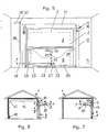
- Fig. 1
- eine Ansicht auf die Antriebsseite eines erfindungsgemäßen Hubfalttores, das außen auf die Außenwand des zu verschließenden Raums montiert ist und nach außen oben faltet und bei dem die Beschläge auf der Rauminnenseite vorgesehen sind;
- Fig. 2
bis 4 - Schnittansichten des Falttores nach Fig. 1 in der Schließstellung, in halb geöffneter Stellung und in der vollen Öffnungsstellung;
- Fig. 5
- eine Ansicht auf die Antriebsseite eines erfindungsgemäßen Hubfalttores, das innen auf die Außenwand des zu verschließenden Raums montiert ist und nach innen oben faltet und bei dem die Beschläge auf der Rauminnenseite vorgesehen sind;
- Fig. 6
- eine Querschnittansicht einer Halle oder PKW-Garage mit dem außen auf die Außenwand aufgesetzten Tor, das nach außen oben über den Torsturz faltet und bei dem die Ausgleichsgewichte vor der Garagenrückwand vorgesehen sind; und
- Fig. 7
- eine Querschnittansicht einer Halle oder PKW-Garage mit innen auf die Außenwand aufgesetztem Tor, das nach innen oben über den Torsturz faltet.
- Fig. 1
- a view of the drive side of a lifting folding door according to the invention, which is mounted outside on the outer wall of the room to be closed and folds outwards and in which the fittings are provided on the inside of the room;
- 2 to 4
- Sectional views of the folding door of Figure 1 in the closed position, in the half-open position and in the full open position.
- Fig. 5
- a view of the drive side of a lift folding door according to the invention, which is mounted on the inside of the outer wall of the room to be closed and folds inwards and in which the fittings are provided on the inside of the room;
- Fig. 6
- a cross-sectional view of a hall or car garage with the outside placed on the outer wall gate that folds out over the top of the lintel and in which the counterweights are provided in front of the back wall of the garage; and
- Fig. 7
- a cross-sectional view of a hall or car garage with the gate placed on the inside of the outside wall, which folds inwards over the lintel.
In den Fig. 6 und 7 erkennt man in einer Schnittansicht eine PKW-Garage 1 mit einer Außenwand
2, auf deren Außenseite 3, s. auch Fig. 5, oder auf deren Innenseite 4, s. auch
Fig. 1 bis 4, vor einer Toröffnung 5 ein Hubfalttor 6 mit einem Torblatt 7 aus einer oberen
Torblatthälfte 8 und einer unteren Torblatthälfte 9 und mit einer Torzarge 10 aus einer
Sturzzarge 11 und zwei Seitenzargen 12 angebracht ist. Diese PKW-Garage steht stellvertretend
auch für Hallen oder Verkaufsgeschäfte mit Schaufenstern, die ebenfalls durch ein
Hubfalttor bzw. einen Hub(fenster)laden oder Hubgitter zu verschließen sind.6 and 7 can be seen in a sectional view of a
Wie insbesondere den Fig. 1 und 5 entnehmbar ist, haben die obere Torblatthälfte 8 und
die untere Torblatthälfte 9 ziemlich gleiche Größe. Sie sind in halber Höhe des Torblatts
mittels Scharnieren 15 gelenkig miteinander verbunden. An der Oberkante der oberen
Torblatthälfte 8 sind weitere Scharniere 16 vorgesehen, mit denen die obere Torblatthälfte
mit der Zarge 11 des Torsturzes gelenkig verbunden ist, die oberhalb des Torsturzes
13 auf der Außenseite der zu verschließenden Garage befestigt ist. As can be seen in particular from FIGS. 1 and 5, the upper
Die untere Kante der unteren Torblatthälfte 9 ist mittels Laufrollen 17, die auf dort seitlich
abstehenden Achsen gelagert sind, in im Bereich der seitlichen Torzargen angebrachten
Führungsschienen 18 vertikal geführt.The lower edge of the lower half of the
An der unteren Torblatthälfte 9 befindet sich ein an sich bekanntes Schloss 20 mit nach
unten vorstehender, kurzer Schlossstange 21, in das ein Sicherheitszylinder 22 eingesetzt
ist, mit dem eine mit der Schlossstange verbundene Betätigungsstange 24 gegen Federspannung
aus einer unteren Stellung in eine obere Stellung zurückgezogen werden kann.
Die Betätigungsstange 24 ist mittels Laschen 23 an der unteren Torblatthälfte 9 längsverschieblich
befestigt. Zur Betätigungsstange 24 führen auch zwei schematisch angedeutete
Bowdenzüge 28 zur Betätigung von seitlich an der unteren Torblatthälfte 9 angebrachten
federnd einschnappenden Verriegelungsgliedern 29, die nahe den Scharnieren 15 seitlich
in die Seitenzargen 12 eingreifen, um in der Schließstellung ein Öffnen des Tors, z. B.
durch mechanische Eingriffe, zu verhindern.On the lower half of the
Zum Öffnen und Schließen des Hubfalttors 6 dient ein selbsthemmender Getriebemotor
35. Bei PKW-Garagen oder Fensterläden handelt es sich vorzugsweise um einen selbsthemmenden
Scheibenwischer-Getriebemotor für Kraftfahrzeuge, der gemäß Fig. 1 nahe
der Oberkante der oberen Torblatthälfte 8, z. B. mit vier Schrauben, befestigt ist. Für
größere Hallentore werden größere Motoren eingesetzt. Auf der Abtriebswelle des Motors
befindet sich eine Gurtrolle 37, von der ein Zuggurt 38 bis nahe zur Unterkante der unteren
Torblatthälfte 9 geführt ist, wo er an einem von der Betätigungsstange 24 seitlich
abstehenden Befestigungshalter 32 befestigt ist. Auf diese Weise dreht sich die Gurtrolle
37 beim Impuls "öffnen", um den Zuggurt 38 oder ein Stahlseil aufzurollen. Bei den ersten
ca. 30 - 40 mm der Drehung der Gurtrolle wird der Gurt um ca. 30 mm aufgerollt,
wodurch die Betätigungsstange 24 um ca. 30 mm angehoben wird. Durch das Anheben
dieser Stange werden gleichzeitig zu den seitlichen Verriegelungsgliedern 29 führende
Bowdenzüge 28 gespannt. Die Schlossstange 21 des Schlosses hat unmittelbar keine
Schließfunktion, sondern nur eine Betätigungsfunktion. Die Verriegelungsglieder 29 werden
links und rechts in der Nähe der Mitte der seitlichen Laibung der Toröffnung entriegelt.
Danach beginnt das Öffnen des Tores, indem es vom Zuggurt 38, der auf die Gurtrolle
aufgerollt wird, faltend nach oben gezogen wird, wo die beiden Torblatthälften 8 und
9 im spitzen Winkel über dem Torsturz durch automatisches Abschalten des Motors stehenbleiben,
s. Fig. 3.A self-locking geared motor is used to open and close the
Zur Erleichterung des Öffnungs- und Schließvorganges sind Ausgleichsgewichte 40 zu
beiden Seiten des Torblatts hinter, neben oder in den seitlichen Torzargen 12 vorgesehen,
die an einem oder zwei Zugseilen 42 hängen und sich in der Schließstellung des Tors
nahe dem Torsturz 13 befinden. Das untere oder freie Ende jedes Zugseils 42 ist an einem
Horizontalriegel 44 verankert, der nahe der Unterkante der unteren Torblatthälfte 9
an dieser in deren Ebene abstehend angebracht ist, s. Fig. 1. Vom Horizontalriegel 44
laufen, wie die Fig. 1 zeigt, jeweils zwei Zugseile 42 zunächst zu einer Seilrolle 46, die
oberhalb der Toröffnung im Bereich des Torsturzes 13 an der Sturzzarge 11 gelagert ist,
s. Fig. 1 und 3. Damit kann jedes Ausgleichsgewicht 40 in an sich bekannter Weise eine
Öffnungskraft auf die untere Torblatthälfte 9 und damit über diese auf die obere Torblatthälfte
8 ausüben, um deren das Tor in die Schließstellung ziehendes Eigengewicht weitestgehend
auszugleichen. Auf diese Weise lässt sich das Tor, z. B. von Hand, vergleichsweise
leicht öffnen und schließen. Zunächst wird das Tor durch die Ausgleichsgewichte 40
so eingestellt, dass sie das Torblatt nach der Entriegelung von allein langsam nach oben
ziehen. Erst durch die Anbringung von zusätzlichen Tariergewichten 50, z. B. am unteren
Torblattrand, wird das Torblatt in die Schließstellung gedrängt und verbleibt in dieser. So
hat der Käufer eines Tores die Möglichkeit zu entscheiden, ob er bei Handbetätigung
bleibt und den Elektroantrieb später mit wenigen Schrauben am oberen Rand der oberen
Torblatthälfte 8 anbringt. Bei Betätigung von Hand, z. B. nach einem Stromausfall, werden
zwei bis drei der Tariergewichte 50 abgenommen, so dass das Torblatt nun nach oben
gedrängt wird. Das Tor lässt sich dann sehr leicht mit zwei Fingern öffnen und schließen.
In der vollständigen Öffnungsstellung haben sich die beiden Ausgleichsgewichte 40 völlig
abgesenkt, s. Fig. 4, und die beiden Torblatthälften sind gegeneinandergefaltet und bilden
am mittigen Gelenkbereich einen sehr spitzen Winkel miteinander, s. ebenfalls Fig. 4.
Durch die Verwendung eines selbsthemmenden Getriebemotors für den Antrieb braucht
die Energiezufuhr zum Antriebsmotor nur unterbrochen zu werden, um das gefaltete Torblatt
in dieser Stellung sicher zu halten.In the fully open position, the two
Die Ausgleichsgewichte 40 können auch an durch die vordere Garagenwand zur Rückwand
der Garage über die Umlenkrollen 46 und vor der Rückwand angebrachte Umlenkrollen
47 geführte Seile 42 angehängt sein, wie dies Fig. 6 zeigt.The
An beiden Seiten der Torblatthälften ist ferner jeweils eine weiche Schraubenfeder 55 von
10 bis 20 mm Durchmesser vorgesehen, die am einen Ende im unteren Bereich der Seitenzarge
12 befestigt ist und am anderen, freien Ende in einem Schlitten 58 im oberen
Bereich an der Seitenzarge 12 verschieblich gleitet. Der Schlitten 58 reicht in den Bewegungsbereich
der Laufrolle 17 der unteren Torblatthälfte, damit er von dieser mitgenommen
werden kann. Die Wahl der Befestigungs- und Anschlagpunkte und der Länge der
Federn ist derart, dass die Federn erst während der letzten Bewegungsphase auf die untere
Kante der unteren Torblatthälfte eine nach unten gerichtete Kraft ausüben, wie dies
aus Tab. 1 ersichtlich ist.

In Tabelle 1 sind für ein schweres und ein leichtes Torblatt jeweils die in den Höhenlagen
0,5 m, 1,0 m, 1,5 m, 2,0 m und 2,5 m erforderlichen Öffnungskräfte aufgeführt. Dabei ist
bei einem schweren Torblatt in den unteren Lagen bis etwa 1,0 m die Öffnungskraft rund
2 kg, darüber 3 kg und schließlich in der letzten Öffnungsphase 3,2 kg. Entsprechend sind
die erforderlichen Kräfte bei einem leichten Torblatt bis etwa über die mittlere Lage jeweils
1 kg, darüber 2 kg und schließlich 2,5 kg. Man sieht, dass die Schraubenfedern 55
erst in der letzten Bewegungsphase eine Schließkraft auf das Tor auszuüben beginnen.
Durch diese zusätzlichen weichen Schraubenfedern wird der Vorteil erreicht, dass das
Hubfalttor (oder der Hubfensterladen) auch bei winterlicher Vereisung bei längerer Öffnung
sofort und nicht ruckartig zum Verschließen nach unten sinkt. Diese Schraubenfedern
bieten also eine Starthilfe, auch wenn sie einen Durchmesser von beispielsweise nur
10 bis 15 mm haben. Nach der Entriegelung, wenn sich die zwei Torhälften nach oben
falten, werden diese beiden als Zugfedern wirkenden Schraubenfedern frühestens ab etwa
halber Torhöhe, z. B. mit dem an der Seitenzarge verschieblichen Schlitten, von der
unteren Torblatthälfte nach oben gezogen und leicht gespannt. Beim Absenken des Torblatts
dienen diese Zugfedern somit als Starthilfe, insbesondere bei Frost und Vereisung,
aber auch bei Windlast.Table 1 shows those for a heavy and a light door leaf in the higher elevations
0.5 m, 1.0 m, 1.5 m, 2.0 m and 2.5 m required opening forces listed. It is
with a heavy door leaf in the lower layers up to approximately 1.0 m, the opening force is round
2 kg, above 3 kg and finally 3.2 kg in the last opening phase. Are accordingly
the required forces for a light door leaf up to about the middle position in each
Mit den am unteren Rand der unteren Torblatthälfte 9 abnehmbar gesichert befestigten
Tariergewichten 50 lässt sich sowohl ein Feinabgleich der Ausgleichsgewichte 40 bewirken
als auch die Wirkung der Zugfedern 55 beeinflussen. Vor allem dienen sie dazu, vor Ort
zu bestimmen, ob das Tor für Handbetrieb nach Entriegelung langsam nach oben gleitet
oder bei Elektroantrieb nach dem Signal "schließen" langsam nach unten gleitet und automatisch
einrastet.With the detachably secured at the lower edge of the lower
Die Tariergewichte könne unterschiedlich ausgebildet sein. So können sie die Form von Metallgewichten aus Gusseisen oder die von Flaschen oder Zylindern haben. Es lassen sich auch leere Flaschen, insbesondere aus Kunststoff verwenden, die mit z.B. Sand o. dgl. gefüllt werden. Die Formgebung ist unkritisch. Die Tariergewicht müssen sich aber in ihrer Lage lösbar sichern lassen, damit sie nicht beim Öffnen des Tors ungewollt aus ihrer Halterung herausfallen.The buoyancy weights can be designed differently. So they can take the form of Have metal weights made of cast iron or of bottles or cylinders. Leave it empty bottles, especially those made of plastic, which are used with e.g. Sand or Like. Be filled. The shape is not critical. The buoyancy weight must be in have their position releasably secured so that they do not get out of their way when you open the gate Bracket fall out.
Sollte der 24V-Scheibenwischer-Getriebemotor 35 einmal ausfallen oder sollte die Stromzufuhr
ausbleiben, die über ein nicht dargestelltes Kabel von der Sturzzarge 11 oder vom
Torsturz 13 her erfolgt, sind nur die Tariergewichte 50 am unteren Rand der unteren Torblatthälfte
9 soweit zu verringern, bis das Falttor schon bei leichtem Fingerstoß von selbst
und ohne Motor nach oben in die Öffnungsstellung gleitet und dort stehen bleibt.Should the 24V windshield wiper geared
Bei einer Not-Handbetätigung des Tors werden der oder jeder Zuggurt 38 zum Heben und
Senken des Hubfalttores, damit er nicht störend herumhängt, mit zwei Schnapphaken
etwa in der Mitte der Querteilung des Torblatts eingehängt, was nicht dargestellt ist. Beim
elektrischen Öffnen haken die Gurte automatisch aus.In the event of an emergency manual operation of the gate, the or each
Das Ein- und Ausschalten sowie eine fernerhin für erforderlich gehaltene Antriebsregelung
des Getriebemotors 35 kann in bekannter Weise mit bekannten Mitteln erfolgen. Eine
Funksteuerung kann vorgesehen werden.Switching on and off and a drive control that is also considered necessary
of the
Die Verriegelung oder Entriegelung des Tores kann von außen mittels Schlüssel und Drehen
des Handgriffes des Sicherheitsschlosses vorgenommen werden. Wird ein Schließimpuls
durch Sender oder durch Druckknopfschalter in bekannter Weise ausgelöst, sinkt das
offene Falttor durch das Eigengewicht, gegebenenfalls unterstützt durch die Zugfedern
55, jedoch gebremst durch den Getriebemotor mit Sperrgetriebe, langsam nach unten, bis
die Rastteile der seitlichen Verriegelungsglieder 29 in die Seitenzargen 12 einrasten. Bei
Stromausfall können auch diese Verriegelungsglieder mit einem Schlüssel über das Zylinderschloss,
die Schlossstange 21, die Betätigungsstange 24 und die Bowdenzüge 28 in
bekannter Weise wie eine Haustür entriegeln und kann das Hubfalttor von Hand geöffnet
werden. Anstelle der Verriegelungsglieder 29 können auch gefederte Schließstangen, die
über Umlenkungen, z. B. Kipphebel, von der Betätigungsstange 24 aus betätigt werden,
vorgesehen sein (nicht dargestellt).The gate can be locked or unlocked from the outside using a key and turning
the handle of the security lock. Will a closing pulse
triggered by transmitter or by push button switch in a known manner, that decreases
open folding door due to its own weight, possibly supported by the tension springs
55, but slowed down by the geared motor with locking gear, slowly downwards until
snap the locking parts of the
Die seitlichen Ausgleichsgewichte 40 sind aus Sicherheitsgründen zweckmäßigerweise
jeweils an zwei Zugseilen 42 aufgehängt, damit im Falle des Reißens eines Seils das Gewicht
in der Seitenzarge schief hängt und ein laut hörbares, alarmierendes Kratzgeräusch
erzeugt, bis der Schaden behoben ist.The
Bei der Ausführungsform nach den Fig. 5 und 7 faltet das Torblatt nach innen oben. Die
Beschläge müssen auf der Innenseite der unteren Torblatthälfte 9 und der Antriebsmotor
35 innen am Torsturz 13 neben der seitlichen Laibung der Toröffnung 5 angebracht sein.
Ausgleichsgewichte 40 laufen innen neben den seitlichen Torzargen 12. Die sie tragenden
Zugseile 42 verlaufen hier in den seitlichen Führungsschienen 18 zu den seitlich nahe der
Unterkante der unteren Torblatthälfte 9 abstehenden Achsen der Laufrollen 17. Zum Öffnen
und Schließen des Tors ist ein innen am Torsturz 12 oder der Sturzzarge 11 neben
der Toröffnung 5 angebrachter Antriebsmotor 35 mit einer Gurtrolle 37 auf der Abtriebswelle
befestigt. Zur Betätigung der Betätigungsstange 24 und zum Hochziehen der unteren
Torblatthälfte 9 ist ein etwa horizontaler, sich über die eine Torblattseite hinaus
erstreckender Kipphebel 25 seitlich der Betätigungsstange 24 in einem Lager 26 gelagert.
Am überstehenden Ende des Kipphebels greift das freie Ende des Zuggurts 38 der Gurtrolle
37 an. Der Kipphebel 25 ist mit Laschen 23, s. Fig. 5, gehalten und an der Betätigungsstange
24 mit einem Zapfen 27 angelenkt.In the embodiment according to FIGS. 5 and 7, the door leaf folds inwards upwards. The
Fittings must be on the inside of the lower
Bei Kühlräumen oder Kühlhäusern können je eines der neuen Hubfalttore auf der Außenseite und auf der Innenseite der Toröffnung montiert sein, wobei sich das Außentor über dem Torsturz faltet und das Innentor sich auf der Innenseite des Torsturzes faltet, wodurch eine sehr günstige Isolierung der Toröffnung erreichet wird.For cold rooms or cold stores, one of the new fold-up doors can be on the outside and be mounted on the inside of the door opening, with the outer door overlapping the lintel folds and the inner gate folds on the inside of the lintel, causing very favorable insulation of the gate opening is achieved.
Claims (9)
dadurch gekennzeichnet, dass der Getriebemotor (35) im mittleren Bereich der Oberkante der oberen Torblatthälfte (8) befestigt ist und der Zuggurt (38) direkt zu einem an der vom Schloss (20) betätigten Betätigungsstange (24) vorgesehenen Befestigungshalter (32) geführt ist. Lift folding gate according to claim 1,
characterized in that the geared motor (35) is fastened in the central region of the upper edge of the upper half of the door leaf (8) and the tension belt (38) is guided directly to a fastening bracket (32) provided on the actuating rod (24) actuated by the lock (20) ,
dadurch gekennzeichnet, dass der Getriebemotor (35) im Bereich des Torsturzes neben der Türöffnung vorgesehen ist und der Gurt neben der Toröffnung zu einem von der vom Schloss (20) betätigten Betätigungsstange (24) über die Torblattseitenkante hinausreichenden, an der Innenfläche der unteren Torblatthälfte (9) gelagerten Kipphebel (25) geführt ist.Lift folding gate according to claim 1,
characterized in that the geared motor (35) is provided in the area of the lintel next to the door opening and the belt next to the door opening to the inside surface of the lower half of the door leaf (which extends from the actuating rod (24) actuated by the lock (20) beyond the side of the door leaf) ( 9) mounted rocker arm (25) is guided.
dadurch gekennzeichnet, dass der selbsthemmende Getriebemotor (35) ein selbsthemmender Scheibenwischergetriebemotor ist.Folding gate according to one of claims 1 to 3,
characterized in that the self-locking gear motor (35) is a self-locking wiper gear motor.
dadurch gekennzeichnet, dass zur Vermeidung von Unfällen das Schließen des Tors durch die Getriebesperre des Getriebemotors bei auf 1 - 2 kg reduziertem Torblatteigengewicht - und nicht durch Motorkraft - erfolgt.Lift folding gate according to one of claims 1 to 4,
characterized in that, in order to avoid accidents, the door is closed by the gear lock of the geared motor with the door leaf weight reduced to 1 - 2 kg - and not by motor power.
dadurch gekennzeichnet, dass an jeder Seite der seitlichen Torzarge (12) eine weiche Schraubenfeder (55) vorgesehen ist, deren eines Ende mit dem unteren Bereich der Seitenzarge (12) verbunden ist und deren anderes Ende an einem Schlitten (58) befestigt ist, der beim Öffnungsvorgang an oder in der seitlichen Laufschiene (18) gleitet und von der unteren Torblatthälfte (9) oder deren Laufrolle (17) in der letzten Phase des Öffnungsvorgangs mitgenommen wird und dabei die Schraubenfeder (55) so spannt, dass sie die Schließbewegung zu Beginn des Schließens zur Überwindung des oberen Totpunktes zu unterstützen vermag.Folding gate according to one of claims 1 to 5,
characterized in that a soft coil spring (55) is provided on each side of the side door frame (12), one end of which is connected to the lower region of the side frame (12) and the other end of which is attached to a slide (58) which during the opening process, it slides on or in the side running rail (18) and is carried along by the lower half of the door leaf (9) or its roller (17) in the last phase of the opening process, thereby tensioning the coil spring (55) so that it closes the closing movement at the beginning of closing to help overcome top dead center.
dadurch gekennzeichnet, dass am unteren Rand der unteren Torblatthälfte zusätzliche Tariergewichte (50) lösbar befestigt sind.Lift folding gate, in particular according to one of claims 1 to 6,
characterized in that additional buoyancy weights (50) are detachably attached to the lower edge of the lower half of the door leaf.
dadurch gekennzeichnet, dass die Ausgleichsgewichte (40) innerhalb der Seitenzargen (12) nach oben und nach unten bewegbar angeordnet sind. Folding gate according to one of claims 1 to 7,
characterized in that the counterweights (40) are arranged to be movable upwards and downwards within the side frames (12).
dadurch gekennzeichnet, dass die Ausgleichsgewichte (40) vor der Rückwand des zu verschließenden Raums nach oben und nach unten bewegbar angeordnet sind.Folding gate according to one of claims 1 to 7,
characterized in that the counterweights (40) in front of the rear wall of the space to be locked are arranged to be movable upwards and downwards.
Applications Claiming Priority (2)
| Application Number | Priority Date | Filing Date | Title |
|---|---|---|---|
| DE10124359A DE10124359C1 (en) | 2001-05-18 | 2001-05-18 | Folding lift-up garage door or window shutter has closure lock operating rod coupled to tension band wound onto roller operated by electric drive motor |
| DE10124359 | 2001-05-18 |
Publications (2)
| Publication Number | Publication Date |
|---|---|
| EP1258588A2 true EP1258588A2 (en) | 2002-11-20 |
| EP1258588A3 EP1258588A3 (en) | 2005-03-02 |
Family
ID=7685349
Family Applications (1)
| Application Number | Title | Priority Date | Filing Date |
|---|---|---|---|
| EP02011072A Withdrawn EP1258588A3 (en) | 2001-05-18 | 2002-05-17 | Vertically folding gate for garages and the like |
Country Status (2)
| Country | Link |
|---|---|
| EP (1) | EP1258588A3 (en) |
| DE (1) | DE10124359C1 (en) |
Cited By (4)
| Publication number | Priority date | Publication date | Assignee | Title |
|---|---|---|---|---|
| ES2308881A1 (en) * | 2006-03-03 | 2008-12-01 | Industrial Grahermetic S.A.E | Folding celosia (Machine-translation by Google Translate, not legally binding) |
| CN102041937A (en) * | 2010-12-02 | 2011-05-04 | 特威盾门业(苏州)有限公司 | Electrical device for opening and closing folding door or window |
| WO2017207102A3 (en) * | 2016-06-03 | 2018-03-08 | Belu Verwaltungsgesellschaft Mbh | Overhead folding system and locking device, drive device and frame therefor |
| CN111852231A (en) * | 2020-03-09 | 2020-10-30 | 广州市好的门窗有限公司 | Method for realizing hovering of lifting door and window at any position |
Families Citing this family (3)
| Publication number | Priority date | Publication date | Assignee | Title |
|---|---|---|---|---|
| DE10327267A1 (en) * | 2003-06-17 | 2005-01-20 | Hörmann KG Antriebstechnik | emergency unlocking |
| DE102015211980B4 (en) | 2015-06-26 | 2023-11-02 | Alpha Deuren International Bv | Locking device for a one-part or multi-part gate |
| CN110053204A (en) * | 2019-01-16 | 2019-07-26 | 嘉兴市金日不锈钢机械有限公司 | A kind of equipment for after-treatment of rubber product |
Citations (1)
| Publication number | Priority date | Publication date | Assignee | Title |
|---|---|---|---|---|
| US1872177A (en) * | 1931-12-03 | 1932-08-16 | Peelle Co The | Operator for canopy type doors |
Family Cites Families (13)
| Publication number | Priority date | Publication date | Assignee | Title |
|---|---|---|---|---|
| US1724995A (en) * | 1922-11-20 | 1929-08-20 | Ernest R Wilson | Garage door |
| US2393052A (en) * | 1945-03-13 | 1946-01-15 | Truscon Steel Co | Bifold canopy door |
| US3224493A (en) * | 1962-04-30 | 1965-12-21 | Cons Electronics Ind | Door and control system therefor |
| DE1708428A1 (en) * | 1967-11-06 | 1971-05-06 | Braunkohlen Und Brikett Ind Ag | Upward pivoting door leaves for buildings, especially for garages |
| US3504249A (en) * | 1968-05-16 | 1970-03-31 | Gen Dynamics Corp | Non-linear quickened monitor and controller |
| DE2001349C3 (en) * | 1970-01-13 | 1975-03-27 | Erich La-Punt Chamues-Ch Doering (Schweiz) | Swinging folding door |
| AU446558B2 (en) * | 1970-07-30 | 1974-03-08 | Richards, Reynald Baddely | Lift-up door |
| US4026343A (en) * | 1975-08-21 | 1977-05-31 | James Don E | Counterweighted bifold closures |
| US4448232A (en) * | 1982-05-03 | 1984-05-15 | Erect-A-Tube, Inc. | Bi-fold door assembly |
| DE9301447U1 (en) * | 1993-02-03 | 1993-03-25 | Fabritz, Gerhard, 4150 Krefeld, De | |
| DE4425371A1 (en) * | 1994-07-19 | 1996-01-25 | Alltronik Gmbh | Drive for opening and closing gates using sprocket and chain |
| ES1029472Y (en) * | 1994-10-17 | 1995-11-01 | Larraya Rufino Lumbier | MECHANISM FOR LIFTING DOORS. |
| DE19516070A1 (en) * | 1995-05-04 | 1996-11-07 | Heidelberger Druckmasch Ag | Bridging arrangement for axis-parallel cylinder duct of rotary printing machines |
-
2001
- 2001-05-18 DE DE10124359A patent/DE10124359C1/en not_active Expired - Fee Related
-
2002
- 2002-05-17 EP EP02011072A patent/EP1258588A3/en not_active Withdrawn
Patent Citations (1)
| Publication number | Priority date | Publication date | Assignee | Title |
|---|---|---|---|---|
| US1872177A (en) * | 1931-12-03 | 1932-08-16 | Peelle Co The | Operator for canopy type doors |
Cited By (5)
| Publication number | Priority date | Publication date | Assignee | Title |
|---|---|---|---|---|
| ES2308881A1 (en) * | 2006-03-03 | 2008-12-01 | Industrial Grahermetic S.A.E | Folding celosia (Machine-translation by Google Translate, not legally binding) |
| CN102041937A (en) * | 2010-12-02 | 2011-05-04 | 特威盾门业(苏州)有限公司 | Electrical device for opening and closing folding door or window |
| CN102041937B (en) * | 2010-12-02 | 2013-04-03 | 特威盾门业(苏州)有限公司 | Electrical device for opening and closing folding door or window |
| WO2017207102A3 (en) * | 2016-06-03 | 2018-03-08 | Belu Verwaltungsgesellschaft Mbh | Overhead folding system and locking device, drive device and frame therefor |
| CN111852231A (en) * | 2020-03-09 | 2020-10-30 | 广州市好的门窗有限公司 | Method for realizing hovering of lifting door and window at any position |
Also Published As
| Publication number | Publication date |
|---|---|
| DE10124359C1 (en) | 2002-11-14 |
| EP1258588A3 (en) | 2005-03-02 |
Similar Documents
| Publication | Publication Date | Title |
|---|---|---|
| EP1250509B1 (en) | Sectional lifting door or folding door | |
| DE202008018015U1 (en) | Fitting for a sliding sash | |
| DE4003218A1 (en) | Counterbalanced sectional door - has weight counterbalanced by torsion spring and safety catch to hold door if spring breaks | |
| CH700929B1 (en) | From the elevator car maintainable drive for an elevator car. | |
| DE19753132B4 (en) | Fire protection sliding door system | |
| EP0140930B1 (en) | Cabin for passengers | |
| DE10124359C1 (en) | Folding lift-up garage door or window shutter has closure lock operating rod coupled to tension band wound onto roller operated by electric drive motor | |
| EP0897448B1 (en) | Sectional gate | |
| DE4430740C2 (en) | Motorized device for closing an opening | |
| DE202008001121U1 (en) | Gate, in particular sectional door, and door drive | |
| EP2216494B1 (en) | Building shadowing device with extendable guide rails | |
| EP1524400B1 (en) | Roller shutter device with variable horizontal slit-shaped opening | |
| EP3695081B1 (en) | Lower door section having a folding roller bracket | |
| EP1366259B1 (en) | Sectional door | |
| DE202005006255U1 (en) | Power-operated door used as a garage door comprises a drive arrangement having a motor and a traction gearing having a traction device which is tensioned relative to the door leaf in the opening direction | |
| EP1630343B1 (en) | Overhead door for collective garages | |
| DE4334403A1 (en) | Swinging sliding door | |
| EP3464766B1 (en) | Overhead folding system with locking device and drive device | |
| WO2021069241A1 (en) | Opening device for a turn-tilt sash of a window or door | |
| DE2001349A1 (en) | Swinging folding door | |
| DE10037329A1 (en) | Sectional vertical lift door or overhead door comprises a smaller door composed of several sections that tilt relative to one another and whose tilting axis runs coaxially to the tilting axis of the larger door sections | |
| DE19646911A1 (en) | Pivoting shutter for window or door opening with electric motor drive for opening and closing | |
| RU14447U1 (en) | LIFTING GATE | |
| DE19958469C1 (en) | Security door for a bank etc has a lever arm at the upper hinge pin which acts on an obstruction to stop the door movement and prevent any injury | |
| DE19709931A1 (en) | Up-and-over gate for high rooms |
Legal Events
| Date | Code | Title | Description |
|---|---|---|---|
| PUAI | Public reference made under article 153(3) epc to a published international application that has entered the european phase |
Free format text: ORIGINAL CODE: 0009012 |
|
| AK | Designated contracting states |
Kind code of ref document: A2 Designated state(s): AT BE CH CY DE DK ES FI FR GB GR IE IT LI LU MC NL PT SE TR |
|
| AX | Request for extension of the european patent |
Free format text: AL;LT;LV;MK;RO;SI |
|
| PUAL | Search report despatched |
Free format text: ORIGINAL CODE: 0009013 |
|
| AK | Designated contracting states |
Kind code of ref document: A3 Designated state(s): AT BE CH CY DE DK ES FI FR GB GR IE IT LI LU MC NL PT SE TR |
|
| AX | Request for extension of the european patent |
Extension state: AL LT LV MK RO SI |
|
| 17P | Request for examination filed |
Effective date: 20050902 |
|
| AKX | Designation fees paid |
Designated state(s): AT BE CH CY DE DK ES FI FR GB GR IE IT LI LU MC NL PT SE TR |
|
| GRAP | Despatch of communication of intention to grant a patent |
Free format text: ORIGINAL CODE: EPIDOSNIGR1 |
|
| GRAS | Grant fee paid |
Free format text: ORIGINAL CODE: EPIDOSNIGR3 |
|
| STAA | Information on the status of an ep patent application or granted ep patent |
Free format text: STATUS: THE APPLICATION HAS BEEN WITHDRAWN |
|
| 18W | Application withdrawn |
Effective date: 20060904 |