EP1256442B1 - Plant, method and apparatus for manufacturing containers - Google Patents
Plant, method and apparatus for manufacturing containers Download PDFInfo
- Publication number
- EP1256442B1 EP1256442B1 EP01830734A EP01830734A EP1256442B1 EP 1256442 B1 EP1256442 B1 EP 1256442B1 EP 01830734 A EP01830734 A EP 01830734A EP 01830734 A EP01830734 A EP 01830734A EP 1256442 B1 EP1256442 B1 EP 1256442B1
- Authority
- EP
- European Patent Office
- Prior art keywords
- belt
- plant
- containers
- previous
- lining
- Prior art date
- Legal status (The legal status is an assumption and is not a legal conclusion. Google has not performed a legal analysis and makes no representation as to the accuracy of the status listed.)
- Expired - Lifetime
Links
Images


Classifications
-
- B—PERFORMING OPERATIONS; TRANSPORTING
- B31—MAKING ARTICLES OF PAPER, CARDBOARD OR MATERIAL WORKED IN A MANNER ANALOGOUS TO PAPER; WORKING PAPER, CARDBOARD OR MATERIAL WORKED IN A MANNER ANALOGOUS TO PAPER
- B31B—MAKING CONTAINERS OF PAPER, CARDBOARD OR MATERIAL WORKED IN A MANNER ANALOGOUS TO PAPER
- B31B50/00—Making rigid or semi-rigid containers, e.g. boxes or cartons
- B31B50/02—Feeding or positioning sheets, blanks or webs
- B31B50/10—Feeding or positioning webs
-
- B—PERFORMING OPERATIONS; TRANSPORTING
- B31—MAKING ARTICLES OF PAPER, CARDBOARD OR MATERIAL WORKED IN A MANNER ANALOGOUS TO PAPER; WORKING PAPER, CARDBOARD OR MATERIAL WORKED IN A MANNER ANALOGOUS TO PAPER
- B31B—MAKING CONTAINERS OF PAPER, CARDBOARD OR MATERIAL WORKED IN A MANNER ANALOGOUS TO PAPER
- B31B2105/00—Rigid or semi-rigid containers made by assembling separate sheets, blanks or webs
-
- B—PERFORMING OPERATIONS; TRANSPORTING
- B31—MAKING ARTICLES OF PAPER, CARDBOARD OR MATERIAL WORKED IN A MANNER ANALOGOUS TO PAPER; WORKING PAPER, CARDBOARD OR MATERIAL WORKED IN A MANNER ANALOGOUS TO PAPER
- B31B—MAKING CONTAINERS OF PAPER, CARDBOARD OR MATERIAL WORKED IN A MANNER ANALOGOUS TO PAPER
- B31B2120/00—Construction of rigid or semi-rigid containers
- B31B2120/40—Construction of rigid or semi-rigid containers lined or internally reinforced
- B31B2120/402—Construction of rigid or semi-rigid containers lined or internally reinforced by applying a liner to already made boxes, e.g. opening or distending of the liner or the box
Definitions
- the present invention relates to the manufacture of containers for housing products.
- the containers are, in particular, in the form of rigid baskets made of plastic material, for instance of polyethylene, destined to house products, preferably produce.
- Document WO-A-9 421 519 discloses a plant for manufacturing containers of ground cellulose or wood pulp while in document EP-A-0 196 799 the containers are made of porous material.
- the present invention refers to a plant according to claim 1.
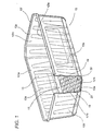
- the containers 12 to be manufactured have at least a bottom wall 12a wherefrom extend respective lateral walls 12b, 12c, 12d, 12e defining a seat 13 for housing the products which is delimited by the inner surface 12'a, 12'b, 12'c, 12'd, 12'e of said walls of the container.
- the inner lining is, in particular, in the form of a shaped sheet 15 of soft material, preferably in the form of a portion of plastic material having swollen cavities 19, defining means for dampening the contact of the produce or the like with the corresponding wall of the container.
- the lining sheet 15 is laid on the upper interior surface of the bottom 12a of the container. Obviously, however, other dispositions and shapes of the present lining means can be imagined.
- thermoforming means essentially known to the person versed in the art, which it is therefore not necessary to described in detail, which produce a continuous carpet or belt of pre-formed containers, in which the individual containers made of rigid plastic material are shaped, by thermoforming.
- thermoformed belt 14 is composed by a plurality of baskets, individually indicated with the numeric reference 12, which are ordered according to respective longitudinal and transverse rows and which are held together by non-shaped portions 14' of said continuous belt made of plastic material, which extend intermediate to the aforementioned baskets 12 and which define scrap portions to be eliminated.
- the plant further comprises, downstream of the thermoforming section, appropriate means, essentially known to the person versed in the art and which it is therefore not necessary to described in detail herein, which provide for separating said containers 12 from the intermediate scrap portion 14' of said pre-formed carpet or belt of containers 14.
- the plant for manufacturing said containers comprises, among said means for forming the containers and said separating means, an appropriate apparatus for readying a respective lining portion 15 inside each of said containers 12.
- the provision for arranging the lining elements, before providing for separating the scrap portions, allows for an easy and quick association of the coating elements to the respective containers, thereby achieving a considerable productivity in the manufacture of containers provided with additional lining elements.
- a preferred embodiment 10 of apparatus for readying an internal lining portion in the containers 12 comprises a support frame 11 that develops longitudinally between a rear end 10a, for the entry of the container belt 14 coming from the thermoforming area, and a front end 10b, for the egress towards the means for separating the containers 12 from the scrap portions 14' of said container belt 14.
- the support frame defines, in particular, a plane 11a of lower support and sliding for said container belt 14, which has a main segment 11'a for conveying the containers, located at a raised level.
- the present embodiment of apparatus then comprises means 16 for advancing said containers, in the form of a continuous belt 14 having a multiplicity of said containers 12 arranged, in particular, on six longitudinal and parallel rows.
- the containers 12 in the container belt 14 are kept mutually linked, thanks to the aforementioned scrap portion 14' of said belt, which is not shaped and extends between each container and the adjacent container, connecting the upper lips or edges 15' (shown in Figures 4 and 5 ) of the lateral walls of said containers 12.
- the means 16 advance said containers with an alternating advancing motion, with advancing phases alternating with motionless phases.
- advancement means 16 are in the form of means acting with thrusting action on said pre-formed container belt 14 and comprise means 16a for engaging said pre-formed belt and means 17 for actuating said engaging means 16.
- the means 17 for actuating said engaging means 16 actuate them according to an alternating forward and backward motion. It is therefore provided for the aforesaid engaging means 16a to be such that, during the advance, they drive the pre-formed belt 14 forward, whilst, during the backwards return phases, they leave the belt 14 in the stopped condition.
- Said engaging means are advantageously in the form of rod means 16a having a respective end 16'a for engaging and thrusting the pre-formed belt of containers 14.
- the rod means 16a by effect of gravity, are kept in contact with the upper surface of said pre-formed belt 14, thereby engaging it in forward driving action, during the phases of forward motion of the rod means 16a.
- said rod means comprise, in particular, a first and a second rod 16a, 16a having a respective pointed end 16'a for engaging with a respective edge 15' of a corresponding container 12 projecting superiorly from the plane defined by said connecting portion 14' of the container belt 14.
- said means 17 for actuating said engaging means 16 comprise cursor means 17a, movable longitudinally on respective longitudinal guides 17b, 17b positioned laterally and supported by the frame of the apparatus.
- the cursor 17a defines support means, whereto said rod means 16a are connected in swivelling fashion, as shown in Figure 5 , and it is in the form of a transverse element that is positioned superiorly to the container belt 14.
- the rod means 16a are pivotally engaged, in 16"a, to a respective bracket 17'a extending superiorly to said transverse body 17a of the cursor.
- the means for actuating the blade means comprise a connecting rod 16c having the ends connected respectively to said cursor means 17a and to a corresponding rotating crank 16d, actuated in rotation by suitable actuating means, better described hereafter.
- a connecting rod 16c and a respective crank 16d are provided at both sides of the cursor 17a.
- the present apparatus further comprises means for providing an internal lining element in said containers.
- said providing means 18 are able to insert said lining element, in particular during a corresponding motionless phase in the advance of the containers 12.
- the providing means comprise means 20 for introducing said sheet 15 into the respective container 12, which means 20 for introducing the lining element 17 in turn comprise means 22 for engaging the lining element 15 and means for actuating said engaging means 22.
- Said engaging means comprise a plate element 22 which, as shown in Figure 3b , has a profile substantially shaped like the peripheral profile of said lining sheet 15.
- a plurality of plates 22 is provided, in the same number as the number of containers 12 present in a transverse row of said container belt 14.
- the means for actuating said engaging means 22 comprise a respective stem 24 for supporting said plate element 22, a block 26 whereto the stems 24 are fastened and means able axially to move said support block 26.
- the means that axially move said block 26 comprise a kinematic mechanism having at least a crank 27 and a corresponding connecting rod 29, which is connected between said crank 27 and said block 26.
- a first and a second said kinematic mechanisms for actuating the block 26 are preferably provided, positioned at the opposite sides of said block 26 to provide a particularly balanced motion of said support 26.
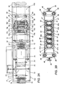
- each crank 27 is set in rotation through a respective shaft 33, which extends transverse to said support frame of the apparatus and is actuated by means of a single electric motor 34 (well shown in Figure 2 ).
- said single motor 34 actuates, through appropriate transmission means 34', two opposite actuating shafts 33, 33.
- Said transmission means comprise a series of gears, housed in a box 34', which are able to cause said first and second shaft 33, 33 to turn in the same direction, which shafts extend from said box 34' in opposite directions to actuate respective kinematic mechanisms of said block 26.
- the means for reading the lining element or sheet 15 comprise means for feeding a continuous belt 35 of material for said lining element and means for cutting the sheets 15 from said continuous belt 35.
- the cutting means comprise, in turn, a cutting blade 36, shaped according to the peripheral profile of said sheet, and means 38 for supporting the cutting blade which are in the form of a respective support block 38 extending transversely to said apparatus.
- said second block or cursor 38 is guided by said first 28, 28 and second 30, 30 pairs of lateral columns and is situated below the first block or cursor 26 for the thruster means 22 for introducing the lining sheets 15 in the respective containers 12.
- the cutting means are provided with appropriate retaining means 40 for said continuous belt 35, which act in correspondence with the area in which the continuous belt 35 is cut.
- said retaining means comprise first retaining means 40a, 40b and opposite second retaining means 40c, 40d, between which is positioned the belt 35 for the manufacture of the lining elements.
- the first retaining means 40a, 40b and the second retaining means 40c, 40d are movable relative to each other from an approached position contacting and retaining the belt 35 and a mutually distanced position of free advancement for said belt 35.
- said first retaining means 40a, 40b are supported movable and said second retaining means 40c, 40d are fastened to the support frame.
- first retaining means 40a, 40b are supported by said movable means for supporting the blade 36, whilst the second retaining means 40c, 40d are supported on a base 40' below the sheet belt 35.
- the first retaining means 40a, 40b are connected capable of axially sliding relative to said second support block 38.
- suitable elastic means 43, 43' are provided which are able to maintain said first retaining elements 40a, 40b in an extended position, which allows to prolong their lower surface, which is able to contact said belt 35, downstream of the cutting end of the cutting blade 36.
- respective stems 41, 41' are provided for supporting the first retaining means 40a, 40b, which are able to slide inside respective seats (not shown in the figures) of the support 38 and about which are wound respective helical thrusting springs 43, 43' acting between said retaining means 40a, 40b and said second support block 38.
- first retaining means and the second retaining means contact said belt 35, in such a way as to define a circumferential space 36' of free axial or vertical motion for the cutting blade 36.
- Said first retaining means comprise, in particular, an internal annular shaped portion 40a, which is able to cooperate in retaining action with an opposite portion 40c of said second retaining means.
- first retaining means comprise an external annulus shaped portion 40b which is able to cooperate with a corresponding external portion 40d of said second retaining means.
- the external portion 40b is coaxially positioned relative to said internal portion 40a and is radially distanced therefrom, in such a way as to define, as shown in Figure 6 , an annular space for said cutting blade 36.
- the external portion 40d of said second means is peripherally positioned around the internal part 40c of said second means and radially distanced therefrom, to define the lower part of said annular space 36' for said blade 36 in cutting action.
- Means are provided for actuating said cutting blade 36 and said retaining means 40, which comprise cam means having a circumferential cam 42, which is actuated in rotation by means of a transverse shaft 50 commanded, through suitable transmission means 52, 54, 56, by the same actuating motor 34 of said insertion means.
- cam means having a circumferential cam 42, which is actuated in rotation by means of a transverse shaft 50 commanded, through suitable transmission means 52, 54, 56, by the same actuating motor 34 of said insertion means.
- the cam 42 has a shaped cam profile 44 for a cam-following roller, or the like, 46, which commands through a connecting rod 48, the vertical motion of the second block or cursor 38, which carries said cutting means.
- said single actuating motor 34 is connected to said cutting means through a transmission chain 52 which connects a respective gear 54 - on the rotation shaft 50 of the cam 42 - to a respective gear 56, on the rotation shaft 33 of the crank 27 of the means for actuating the thrusters 22. Also provided is a chain tensioning sprocket indicated with the numeric reference 58 in Figure 5 .
- the single actuating motor 34 is also connected to said means for advancing the container belt 14 through a respective second transmission chain 60 , which connects a respective gear 62 on the rotation shaft 33 of the crank 16c of the kinematic mechanism actuating the means for advancing the container belt 14 to a respective gear 64 on the rotation shaft 17' of the crank 16c of the means for advancing the container belt 14.
- a sprocket 66 is provided, able to tension said second transmission chain 60.
- the first retaining means 40a and said shaped blade 36 are so shaped as to allow the passage of the plate of the thrusters 22.
- the blocking means 40a have, in correspondence with opposite edges, a horizontal attachment portion 40'a of the support stems 41.
- said thrusting plate 22 therefore has a profile which is provided with recesses in correspondence with said edges projecting horizontally from said first retaining elements 40a.
- said feeding means comprise means 68 for supplying said belt 35, which have sustaining means for reel 70 of material in a belt 35 and means for replacing a depleted reel 72 with a loaded reel 70.
- the means for replacing a depleted reel with a loaded reel comprise a carrousel 74, which is supported free to rotate by said frame 11 and which defines support means for at least a first 70 and a second reel 72.
- Said carrousel 74 is constituted by a main plate 74', which is vertically supported able in rotary fashion by said frame 11, whereto it is connected through a transverse axis 75, in turn supported by a pair of uprights 75', only one being shown in Figure 2 .
- Suitable means are provided for actuating in rotation said reel-bearing carousel 74, in such a way that the latter has, in correspondence with the supply position, a loaded reel 70 and in such a way as to place, simultaneously, the other depleted reel 72, in correspondence with a position suitable for its replacement.
- the aforesaid carrousel 74 is suitable for supporting a third and a fourth reel.
- the third loading reel is shown, indicated with the numeric reference 76.
- the reels are supported in positioned equidistant by an angular segment of 90° relative to each other.
- a series of transverse axes 70', 72', 74', 73' are provided, positioned peripherally to the plate 74' of the carrousel for rotary support relative to the plate of respective loading reels.
- Said attachment means have sealing means 77, preferably ultrasound sealing, and means for approaching the free end to the extreme end.
- the numeric references 77a and 77b indicate electric motors of the system for attaching the sheet belt 35.
- the general reference 78 in Figure 2 indicates a buffer for the definition of a stock of belt 35 to be supplied when replacing the reel.
- Said buffer means comprise a plurality of rollers 80, 82 for the sliding of the belt 35 arranged in zigzag fashion and able to define an elongated path for said belt 35.
- the first plurality of rollers 80 is, as shown in Figure 2 , supported on a fixed longitudinal supported 81, whereto the rollers 80 are connected in freely rotating fashion.
- An additional support 83 movable relative to the first support 81, bears the second plurality of said rollers 82 of the buffer 78.
- An electric motor 85'a actuates, through a respective actuation and transmission system 85', the vertical motion of the longitudinal support 83 on the respective perpendicular stems, indicated with the numeric reference 87 in Figure 2 .
- said buffer means 78 are, advantageously, positioned above the area 10c anterior to the area of insertion of the lining sheet 15. The height extension of the apparatus can thereby be limited.
- first rollers 84, 84 for gripping and driving said sheet belt 35 which are positioned downstream of the area 10c of insertion of the sheets 15 into the respective containers 14, and second rollers 86, 86 for gripping and driving said sheet belt 35, which are positioned upstream of said buffer means 78.
- Third rollers 88, 88 for gripping and driving said sheet belt 35 are in turn positioned downstream of said buffer means 78.
- Said pairs of opposite driving rollers are, as shown, provided with respective actuating motors, indicated with the respective numeric references 85, 87, 89 in Figure 2 .
- said second driving rollers 86, 86 are actuated by means of a stepper motor that allows to supply, to the area 10c of insertion of the lining sheet, a sheet belt having a step-by-step advancement, which exhibits advancement phases alternating with stopped phases, in coincidence with which the sheets 15 are separated from the belt 35 and subsequently inserted into the respective container.
- Said stepper motor thus defines means for the step-by-step advancement of the sheet belt 35 in correspondence with the insertion area 10c.
- Means for collecting the scrap belt comprising a collecting reel 90, supported able to rotate by said frame downstream of the insertion area 10c, in overlying position to the sliding plane 11a of the container belt 14.
- means 92, 94 are further provided for positioning the belt 35 in correspondence with the position for cutting the lining sheet 15 and inserting them into the respective containers 12.
- Said positioning means comprise a first transmission roller 92, positioned upstream of the insertion area 10c, and a second transmission roller 94, positioned downstream of the insertion area.
- Said first and second positioning rollers 92, 94 are supported at the same height level by part of said frame of the apparatus. Said positioning rollers 92, 94 extend transversely and are supported free to rotate on corresponding upward extension arms 92', 94' of a base 95 of said frame which bears said second fixed retaining means 40c, 40d.
- said positioning rollers 92, 94 are such as to retain downwards said belt 35 for the lining sheets in contact with the lower retaining means 40c, 40d.
- means 95 are provided for applying to respective container 12 an adhesive for attaching said lining element or sheet 15 to said container 14, which means are positioned upstream of said insertion area 10c.
- the means 95 for applying the adhesive are supported in a position overlying the plane 11a supporting the container belt 14 and comprise a plurality of glue dispensers transversely equidistant, so as to provide the stream of glue on the bottom wall of the respective container 12.
- Said plane 11a for the sliding of the container belt 14 has at least an upwardly sloped segment 11"a from a lowered sliding level 11'''a to an upper level 11'a, in which said insertion of the lining sheet 15 into the respective containers 12 is carried out.
- the revolving carrousel 74 for supplying the reels of belts for lining sheets 35 is positioned upstream of the raised level area of said sliding plane 11"a for the container belt 14. A greater compactness is thereby obtained in terms of the length of the present apparatus.
- the preferred operating method of the present apparatus is, briefly, as follows.
- the synchronised operation of the present apparatus therefore provides that, as shown in Figure 6 , with the means for cutting and inserting the lining sheet 15 in the raised position, the rod driving means advance the container belt by a predefined step corresponding to the distance between the longitudinal distance between the centres or similar points of the subsequent containers.
- the advancing means 16 move back for a segment equal to the length of said step, until reaching the rear dead centre where the forward thrust for the container belt 14 starts; in this return phase, the container belt 14 is motionless on its support plane 11a.
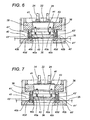
- the block or cursor 38 that carries the retaining means and the shaped cutting blade is made to descend, until the first retaining means 40a, 40b contact the sheet belt 35, as shown in Figure 7 .
- the block 38 carrying cutting means continues its descent and compresses the springs 43, 43' of said first retaining means 40a, 40b, in such a way that they strongly clamp the sheet belt 35, which is motionless on the second retaining means 40c, 40d.
- the part that bears the first retaining means recesses relative to the main part of the block 38, which bears the cutting blade 36, until reaching the position of Figure 8 , in which the cutting blade 36 engages and cuts the respective shaped lining sheet 15 from the sheet belt 35.
- the thruster-bearing block or cursor 26 starts returning upwards, whilst the rod advancing means advance the container belt forward by another longitudinal step. Thereupon, said operations are repeated for a successive transverse row of containers 12 of the container belt 14.
Landscapes
- Cultivation Receptacles Or Flower-Pots, Or Pots For Seedlings (AREA)
- Packaging Frangible Articles (AREA)
- Rigid Containers With Two Or More Constituent Elements (AREA)
- Making Paper Articles (AREA)
- Hydroponics (AREA)
- Cultivation Of Plants (AREA)
- Control Of Driving Devices And Active Controlling Of Vehicle (AREA)
- Biological Depolymerization Polymers (AREA)
- Supplying Of Containers To The Packaging Station (AREA)
Applications Claiming Priority (2)
| Application Number | Priority Date | Filing Date | Title |
|---|---|---|---|
| ITBO010294 | 2001-05-11 | ||
| IT2001BO000294A ITBO20010294A1 (it) | 2001-05-11 | 2001-05-11 | Impianto, procedimento ed apparecchiatura per la realizzazione di contenitori, in particolare per prodotti ortofrutticoli |
Publications (3)
| Publication Number | Publication Date |
|---|---|
| EP1256442A2 EP1256442A2 (en) | 2002-11-13 |
| EP1256442A3 EP1256442A3 (en) | 2003-05-14 |
| EP1256442B1 true EP1256442B1 (en) | 2008-02-27 |
Family
ID=11439339
Family Applications (1)
| Application Number | Title | Priority Date | Filing Date |
|---|---|---|---|
| EP01830734A Expired - Lifetime EP1256442B1 (en) | 2001-05-11 | 2001-11-29 | Plant, method and apparatus for manufacturing containers |
Country Status (4)
| Country | Link |
|---|---|
| EP (1) | EP1256442B1 (it) |
| AT (1) | ATE387308T1 (it) |
| DE (1) | DE60132977D1 (it) |
| IT (1) | ITBO20010294A1 (it) |
Families Citing this family (1)
| Publication number | Priority date | Publication date | Assignee | Title |
|---|---|---|---|---|
| IT1394879B1 (it) * | 2009-07-17 | 2012-07-20 | Taranto | Sistema per la foratura di film plastici |
Citations (1)
| Publication number | Priority date | Publication date | Assignee | Title |
|---|---|---|---|---|
| EP0196799A1 (en) * | 1985-03-11 | 1986-10-08 | Redfearn Flexpack Limited | Improvements in or relating to packaging |
Family Cites Families (3)
| Publication number | Priority date | Publication date | Assignee | Title |
|---|---|---|---|---|
| US3227024A (en) * | 1963-02-27 | 1966-01-04 | Charles H Krebs | Sample cutter |
| US4823660A (en) * | 1986-02-20 | 1989-04-25 | Stelron Components Inc | Label cutting device and method |
| WO1994021519A2 (de) * | 1993-03-18 | 1994-09-29 | Jochen Dietrich | Lebensmittelverpackung, verfahren zur herstellung einer sauerstoffdichten verpackung, vorrichtung zur durchführung eines derartigen verfahrens und dabei verwendete schalenreihe |
-
2001
- 2001-05-11 IT IT2001BO000294A patent/ITBO20010294A1/it unknown
- 2001-11-29 EP EP01830734A patent/EP1256442B1/en not_active Expired - Lifetime
- 2001-11-29 AT AT01830734T patent/ATE387308T1/de not_active IP Right Cessation
- 2001-11-29 DE DE60132977T patent/DE60132977D1/de not_active Expired - Lifetime
Patent Citations (1)
| Publication number | Priority date | Publication date | Assignee | Title |
|---|---|---|---|---|
| EP0196799A1 (en) * | 1985-03-11 | 1986-10-08 | Redfearn Flexpack Limited | Improvements in or relating to packaging |
Also Published As
| Publication number | Publication date |
|---|---|
| ITBO20010294A0 (it) | 2001-05-11 |
| DE60132977D1 (de) | 2008-04-10 |
| ITBO20010294A1 (it) | 2002-11-11 |
| EP1256442A3 (en) | 2003-05-14 |
| EP1256442A2 (en) | 2002-11-13 |
| ATE387308T1 (de) | 2008-03-15 |
Similar Documents
| Publication | Publication Date | Title |
|---|---|---|
| KR101616724B1 (ko) | 제품 공급용 유닛 | |
| US8875477B2 (en) | Beverage pod manufacturing machine | |
| CN108602573B (zh) | 连续进给产品的可伸展膜的包装方法和机器 | |
| CZ279197A3 (cs) | Balicí stroj pro vícenásobná balení | |
| JP2007119068A (ja) | 製品を包装材料からなる少なくとも1つのシートに包装するための方法及び機械 | |
| CA2627868C (en) | Container seals | |
| CN108698718A (zh) | 用于成组进给产品的可伸展薄膜的包装方法和机器 | |
| EP2055637B1 (en) | An apparatus for packing articles, in partcular stickpacks, in relative cartons | |
| EP1256519A1 (en) | An apparatus for wrapping groups of products with plastic film | |
| US6971839B2 (en) | Machine and method for grouping products in stacks having a pre-set length | |
| EP1162142B1 (en) | Device for recovering excess products from a blister band in a blistering machine | |
| EP1256442B1 (en) | Plant, method and apparatus for manufacturing containers | |
| US5040663A (en) | Apparatus and method for stacking | |
| EP2086843B1 (en) | Apparatus for packaging a product | |
| EP0428361A1 (en) | Gum wrapping machine | |
| EP0344716A2 (en) | Apparatus and method for stacking | |
| US6079191A (en) | Automated loading of pickles into jars | |
| RU2437808C2 (ru) | Аппарат для упаковки пастообразных пищевых продуктов | |
| US3237367A (en) | Machine for packaging melted cheese into various presentation packages | |
| EP3221222B1 (en) | Cutting method and unit in a packaging machine for packing products in extensible film | |
| EP3601067B1 (en) | Cutting unit for a packaging machine in extendable film | |
| US5468325A (en) | Process for applying an adhesive band having one adhesive side | |
| KR102087809B1 (ko) | 번들 제조장치 | |
| US3471918A (en) | Machine for placement,cutting,fastening transparent plastic windows in cover rings | |
| CN115735966A (zh) | 一种整形组件和整形系统 |
Legal Events
| Date | Code | Title | Description |
|---|---|---|---|
| PUAI | Public reference made under article 153(3) epc to a published international application that has entered the european phase |
Free format text: ORIGINAL CODE: 0009012 |
|
| AK | Designated contracting states |
Kind code of ref document: A2 Designated state(s): AT BE CH CY DE DK ES FI FR GB GR IE IT LI LU MC NL PT SE TR |
|
| AX | Request for extension of the european patent |
Free format text: AL;LT;LV;MK;RO;SI |
|
| PUAL | Search report despatched |
Free format text: ORIGINAL CODE: 0009013 |
|
| AK | Designated contracting states |
Designated state(s): AT BE CH CY DE DK ES FI FR GB GR IE IT LI LU MC NL PT SE TR |
|
| AX | Request for extension of the european patent |
Extension state: AL LT LV MK RO SI |
|
| RIC1 | Information provided on ipc code assigned before grant |
Ipc: 7B 65D 25/14 B Ipc: 7B 31B 1/16 B Ipc: 7B 65D 81/03 B Ipc: 7B 31B 7/00 A |
|
| 17P | Request for examination filed |
Effective date: 20030716 |
|
| AKX | Designation fees paid |
Designated state(s): AT BE CH CY DE DK ES FI FR GB GR IE IT LI LU MC NL PT SE TR |
|
| AXX | Extension fees paid |
Extension state: RO Payment date: 20030716 Extension state: MK Payment date: 20030716 Extension state: SI Payment date: 20030716 Extension state: AL Payment date: 20030716 Extension state: LV Payment date: 20030716 Extension state: LT Payment date: 20030716 |
|
| 17Q | First examination report despatched |
Effective date: 20040330 |
|
| RAP1 | Party data changed (applicant data changed or rights of an application transferred) |
Owner name: LINPAC PLASTICS ROMAGNA S.R.L. |
|
| RAP1 | Party data changed (applicant data changed or rights of an application transferred) |
Owner name: INFIA S.R.L. |
|
| GRAP | Despatch of communication of intention to grant a patent |
Free format text: ORIGINAL CODE: EPIDOSNIGR1 |
|
| GRAS | Grant fee paid |
Free format text: ORIGINAL CODE: EPIDOSNIGR3 |
|
| GRAA | (expected) grant |
Free format text: ORIGINAL CODE: 0009210 |
|
| AK | Designated contracting states |
Kind code of ref document: B1 Designated state(s): AT BE CH CY DE DK ES FI FR GB GR IE IT LI LU MC NL PT SE TR |
|
| AX | Request for extension of the european patent |
Extension state: AL LT LV MK RO SI |
|
| REG | Reference to a national code |
Ref country code: GB Ref legal event code: FG4D |
|
| REG | Reference to a national code |
Ref country code: CH Ref legal event code: EP |
|
| REG | Reference to a national code |
Ref country code: IE Ref legal event code: FG4D |
|
| REF | Corresponds to: |
Ref document number: 60132977 Country of ref document: DE Date of ref document: 20080410 Kind code of ref document: P |
|
| PG25 | Lapsed in a contracting state [announced via postgrant information from national office to epo] |
Ref country code: FI Free format text: LAPSE BECAUSE OF FAILURE TO SUBMIT A TRANSLATION OF THE DESCRIPTION OR TO PAY THE FEE WITHIN THE PRESCRIBED TIME-LIMIT Effective date: 20080227 Ref country code: ES Free format text: LAPSE BECAUSE OF FAILURE TO SUBMIT A TRANSLATION OF THE DESCRIPTION OR TO PAY THE FEE WITHIN THE PRESCRIBED TIME-LIMIT Effective date: 20080607 |
|
| NLV1 | Nl: lapsed or annulled due to failure to fulfill the requirements of art. 29p and 29m of the patents act | ||
| LTIE | Lt: invalidation of european patent or patent extension |
Effective date: 20080227 |
|
| PG25 | Lapsed in a contracting state [announced via postgrant information from national office to epo] |
Ref country code: AT Free format text: LAPSE BECAUSE OF FAILURE TO SUBMIT A TRANSLATION OF THE DESCRIPTION OR TO PAY THE FEE WITHIN THE PRESCRIBED TIME-LIMIT Effective date: 20080227 |
|
| PG25 | Lapsed in a contracting state [announced via postgrant information from national office to epo] |
Ref country code: BE Free format text: LAPSE BECAUSE OF FAILURE TO SUBMIT A TRANSLATION OF THE DESCRIPTION OR TO PAY THE FEE WITHIN THE PRESCRIBED TIME-LIMIT Effective date: 20080227 |
|
| PG25 | Lapsed in a contracting state [announced via postgrant information from national office to epo] |
Ref country code: SE Free format text: LAPSE BECAUSE OF FAILURE TO SUBMIT A TRANSLATION OF THE DESCRIPTION OR TO PAY THE FEE WITHIN THE PRESCRIBED TIME-LIMIT Effective date: 20080527 Ref country code: NL Free format text: LAPSE BECAUSE OF FAILURE TO SUBMIT A TRANSLATION OF THE DESCRIPTION OR TO PAY THE FEE WITHIN THE PRESCRIBED TIME-LIMIT Effective date: 20080227 Ref country code: PT Free format text: LAPSE BECAUSE OF FAILURE TO SUBMIT A TRANSLATION OF THE DESCRIPTION OR TO PAY THE FEE WITHIN THE PRESCRIBED TIME-LIMIT Effective date: 20080721 Ref country code: DK Free format text: LAPSE BECAUSE OF FAILURE TO SUBMIT A TRANSLATION OF THE DESCRIPTION OR TO PAY THE FEE WITHIN THE PRESCRIBED TIME-LIMIT Effective date: 20080227 |
|
| EN | Fr: translation not filed | ||
| PLBE | No opposition filed within time limit |
Free format text: ORIGINAL CODE: 0009261 |
|
| STAA | Information on the status of an ep patent application or granted ep patent |
Free format text: STATUS: NO OPPOSITION FILED WITHIN TIME LIMIT |
|
| PG25 | Lapsed in a contracting state [announced via postgrant information from national office to epo] |
Ref country code: DE Free format text: LAPSE BECAUSE OF FAILURE TO SUBMIT A TRANSLATION OF THE DESCRIPTION OR TO PAY THE FEE WITHIN THE PRESCRIBED TIME-LIMIT Effective date: 20080528 |
|
| 26N | No opposition filed |
Effective date: 20081128 |
|
| PG25 | Lapsed in a contracting state [announced via postgrant information from national office to epo] |
Ref country code: FR Free format text: LAPSE BECAUSE OF FAILURE TO SUBMIT A TRANSLATION OF THE DESCRIPTION OR TO PAY THE FEE WITHIN THE PRESCRIBED TIME-LIMIT Effective date: 20081212 |
|
| PG25 | Lapsed in a contracting state [announced via postgrant information from national office to epo] |
Ref country code: MC Free format text: LAPSE BECAUSE OF NON-PAYMENT OF DUE FEES Effective date: 20081130 |
|
| REG | Reference to a national code |
Ref country code: CH Ref legal event code: PL |
|
| GBPC | Gb: european patent ceased through non-payment of renewal fee |
Effective date: 20081129 |
|
| PG25 | Lapsed in a contracting state [announced via postgrant information from national office to epo] |
Ref country code: CY Free format text: LAPSE BECAUSE OF FAILURE TO SUBMIT A TRANSLATION OF THE DESCRIPTION OR TO PAY THE FEE WITHIN THE PRESCRIBED TIME-LIMIT Effective date: 20080227 |
|
| PG25 | Lapsed in a contracting state [announced via postgrant information from national office to epo] |
Ref country code: CH Free format text: LAPSE BECAUSE OF NON-PAYMENT OF DUE FEES Effective date: 20081130 Ref country code: IE Free format text: LAPSE BECAUSE OF NON-PAYMENT OF DUE FEES Effective date: 20081201 Ref country code: LI Free format text: LAPSE BECAUSE OF NON-PAYMENT OF DUE FEES Effective date: 20081130 |
|
| PG25 | Lapsed in a contracting state [announced via postgrant information from national office to epo] |
Ref country code: GB Free format text: LAPSE BECAUSE OF NON-PAYMENT OF DUE FEES Effective date: 20081129 |
|
| PG25 | Lapsed in a contracting state [announced via postgrant information from national office to epo] |
Ref country code: LU Free format text: LAPSE BECAUSE OF NON-PAYMENT OF DUE FEES Effective date: 20081129 |
|
| PG25 | Lapsed in a contracting state [announced via postgrant information from national office to epo] |
Ref country code: TR Free format text: LAPSE BECAUSE OF FAILURE TO SUBMIT A TRANSLATION OF THE DESCRIPTION OR TO PAY THE FEE WITHIN THE PRESCRIBED TIME-LIMIT Effective date: 20080227 |
|
| PG25 | Lapsed in a contracting state [announced via postgrant information from national office to epo] |
Ref country code: GR Free format text: LAPSE BECAUSE OF FAILURE TO SUBMIT A TRANSLATION OF THE DESCRIPTION OR TO PAY THE FEE WITHIN THE PRESCRIBED TIME-LIMIT Effective date: 20080528 |
|
| PGFP | Annual fee paid to national office [announced via postgrant information from national office to epo] |
Ref country code: IT Payment date: 20181123 Year of fee payment: 18 |
|
| PG25 | Lapsed in a contracting state [announced via postgrant information from national office to epo] |
Ref country code: IT Free format text: LAPSE BECAUSE OF NON-PAYMENT OF DUE FEES Effective date: 20191129 |