EP1255899B1 - Panneau de construction superposables - Google Patents
Panneau de construction superposables Download PDFInfo
- Publication number
- EP1255899B1 EP1255899B1 EP01951155A EP01951155A EP1255899B1 EP 1255899 B1 EP1255899 B1 EP 1255899B1 EP 01951155 A EP01951155 A EP 01951155A EP 01951155 A EP01951155 A EP 01951155A EP 1255899 B1 EP1255899 B1 EP 1255899B1
- Authority
- EP
- European Patent Office
- Prior art keywords
- panel
- foam
- panels
- projections
- recesses
- Prior art date
- Legal status (The legal status is an assumption and is not a legal conclusion. Google has not performed a legal analysis and makes no representation as to the accuracy of the status listed.)
- Expired - Lifetime
Links
Images


Classifications
-
- E—FIXED CONSTRUCTIONS
- E04—BUILDING
- E04B—GENERAL BUILDING CONSTRUCTIONS; WALLS, e.g. PARTITIONS; ROOFS; FLOORS; CEILINGS; INSULATION OR OTHER PROTECTION OF BUILDINGS
- E04B2/00—Walls, e.g. partitions, for buildings; Wall construction with regard to insulation; Connections specially adapted to walls
- E04B2/84—Walls made by casting, pouring, or tamping in situ
- E04B2/86—Walls made by casting, pouring, or tamping in situ made in permanent forms
- E04B2/8611—Walls made by casting, pouring, or tamping in situ made in permanent forms with spacers being embedded in at least one form leaf
- E04B2/8617—Walls made by casting, pouring, or tamping in situ made in permanent forms with spacers being embedded in at least one form leaf with spacers being embedded in both form leaves
-
- E—FIXED CONSTRUCTIONS
- E04—BUILDING
- E04B—GENERAL BUILDING CONSTRUCTIONS; WALLS, e.g. PARTITIONS; ROOFS; FLOORS; CEILINGS; INSULATION OR OTHER PROTECTION OF BUILDINGS
- E04B2/00—Walls, e.g. partitions, for buildings; Wall construction with regard to insulation; Connections specially adapted to walls
- E04B2/84—Walls made by casting, pouring, or tamping in situ
- E04B2/86—Walls made by casting, pouring, or tamping in situ made in permanent forms
- E04B2002/8694—Walls made by casting, pouring, or tamping in situ made in permanent forms with hinged spacers allowing the formwork to be collapsed for transport
Definitions
- the present invention relates a stockable insulating foam panel and to a wall foam assembly comprising pairs of such opposed stackable insutating foam panels for receiving flowable materials such as concrete.
- a number of different systems and methods currently exist for making insulating forms for casting a concrete wall comprise pairs of opposed foam panels generally made of rigid foam like polystyrene, which define concrete-receiving cavities therebetween. Those pairs of foam panels are placed one above the other so to form the wall form. Once the concrete is solidified, the form walls remain in place to insulate the wall. Those form walls are typically maintained in spaced and parallel relationship before the pouring of concrete by means of connectors comprising a pair of parallel lateral attachment flanges each embedded in one of the two opposed foam panels, and a connecting web interconnecting the flanges.
- the piling up of such panels is performed on the site of construction.
- One object in this field is to obtain foam panels that would allow, on one hand, an easy and very rapid piling up without loosing time and, on the other hand, would allow construction of a stable and solid stacking that will not likely disassemble prior to the pouring of concrete. As can be easily understood, as soon as the concrete is poured, the chances that the stack collapses or disassembles is greatly reduced.
- EP-A-0275938 Another similar example of an insulating construction panel is shown in EP-A-0275938 , which discloses the features of the preamble of claim 1 and of claim 5.
- An object of the present invention is to propose a stackable insulating foam panel that will satisfy the above-mentioned need, and more particularly to propose an improved stackable foam panel that allows the construction of a stable and solid stack.
- a stackable insulating foam panel having a top side and a bottom side each including a median row of alternating projections and recesses having a similar complementary shape, characterised in that the median row of the top side is disposed between two coplanar edge surfaces, above which the projections are projecting and below which the recesses are recessed, and the median row of the bottom side is disposed between co-planar edge surfaces below which the projections are projecting and above which recesses are recessed, each projection and each recess of the top side being opposed respectively to a recess and a projection of the bottom side, whereby the top side and the bottom side of the panel can be interconnected with respectively the bottom side and the top side of like panels.
- the present invention also concerns a wall form assembly comprising opposed foam panels, as described above, disposed in parallel relationship to make a wall form for receiving a flowable material such as concrete and a plurality of connectors for tying the opposed foam panels together.
- the form wall assembly of the invention presents the features of claim 5. It comprises:
- the two coplanar edge surfaces of the foam panel act as shoulders or abutments for the edge surfaces of an interconnected like panel, and thus help to solidify or stabilise a stack built with foam panels according to the present invention.
- a form wall assembly (10) is suitable to make a form for receiving flowable materiel such as concrete or the like.
- the form obtained is of the type comprising a plurality of stacked insulating horizontal rows of coplanar substantially rectangular foamed plastic panels (14) abutting one another along horizontal and vertical sides thereof.
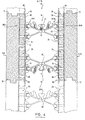
- the form wall assembly (10) comprises a first foam panel (14a) opposed to a second foam panel (14b) in spaced and parallel relationship, and tied together by means of a plurality of connectors (16), as best seen in figure 4 .
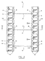
- the foam panels (14) are movable between an extended position, as shown in figure 1 , where the foam panels (14) are spaced-apart to make the form and a collapsed position, not illustrated, where the foam panels (14) are brought close to each other, mainly for shipping purposes.
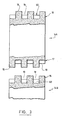
- the foam panels (14) each have a top side (15) opposite a bottom side (17) and, as illustrated in figures 1 and 2 , each of the top side (15) and the bottom side (17) is provided with a median row (13) of alternating projections (18) and recesses (19) having a similar complementary shape.
- This median row (13) is disposed between two coplanar edge surfaces (50) bordering the edges of the panel (14). It has to be noted that the coplanar edge surfaces (50) are preferably provided with a width sufficiently large so as to offer an increased stability between interlocked panels (14).
- each projection (18) and recess (19) of the top side (15) of one panel (14a) is opposed respectively to a recess (19) and a projection (18) of the bottom side (17) of the same panel (14a), and is facing respectively a recess (19) and a projection (18) of the top side (15) of the other panel (14b), when the pair of panels (14a and 14b) are in the extended position as in figure 1 or 2 , whereby the pair of panels (14a, 14b) can be interconnected with a like pair of panels.
- the projections (18) and the recesses (19) are generally rectangular. However, projections and recesses of other shapes such as circular, oblong, square etc. could also be used
- the present invention prefers using projections (18) with rounded-corners. Nevertheless, projections (18) with square-corners or other forms, would still be efficient.
- each of the projections (18) and the recesses (19) has two opposite substantially convex lateral sides (52, 54) which help the insertion of the projections (18) in the recesses (19).
- each connector (16) comprises a pair of anchor members (20a, 20b), a first one (20a) embedded in the first foam panel (14a) and the second one (20b) embedded in the second foam panel (14b).
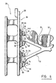
- Each anchor member (20) has an elongated flange plate (22) extending longitudinally and deep inside the foam panel (14) and an elongated link element (24) connected longitudinally to the flange plate (22) and having a projecting end (26) coming out of the foam panel (14).
- the projecting end (26) of each anchor member (20) comprises a stabilising plate (28) as best shown in figure 5 parallel to the flange plate (22) and extending flush with the inner surface (30) of the foam panel (14).
- the link element (24) preferably comprises a plurality of holes (25) therealong.
- the link element (24) may also be plane solid.
- the anchor member (20) is embedded in the foam panel (14)
- the plastic foam material forming the panel (14) is injected to surround the anchor member (20), thereby strengthening the joint between the panel (14) and the anchor member (20) which thus act as an anchor forming part of the foam panel (14).
- the plastic foam material which is preferably polystyrene or any other material known to a person skilled in the field of plastic foam, is injected to surround the anchor member (20).
- the connector (16) further comprises a web member (32) extending between the foam panels (14).
- the web member (32) that is preferably made of a relatively flexible plastic comprises a central portion (44) having a shape adapted to receive and hold metal rods used to reinforce the concrete.
- the web member (32) further has a first longitudinal side end (34a) hingedly connected to the projecting end (26) of the first anchor member (20a) and a second longitudinal side end (34b) opposed to the first longitudinal side end (34a).
- the second longitudinal side end (34b) is hingedly connected to the projecting end (26) of the second anchor member (20b).
- the foam panels (14) are movable between an extended position, as shown in figure 1 , where the foam panels (14) are spaced-apart to make the form and a collapsed position, not illustrated, where the foam panels (14) are brought close to each other, mainly for shipping purposes.
- each connecting element (64) preferably disposed on the stabilising plate (28) of the projecting end (26) of each anchor member (20) in order to hingedly connect the web member (32) to the anchor members (20) is illustrated.
- Each of these connecting elements (64) is shaped to form two aligned ridges (66) projecting from the stabilising plate (28), and the space between them defined a longitudinal sleeve (68).
- a joining pin (70) can be mounted in the sleeve (68).
- pin receiving holes (71) are provided in the ridges (66) for this purpose, each hole (71) facing inwardly of the sleeve (68).
- each longitudinal side end (34a, 34b) of the web member (32) defines a corresponding number of arms (72).
- Each arm (72) has an extremity (74) connectable to a corresponding joining pin (70) so as to be rotatable around an axis defined by the joining pin (70). It can be easily seen that this purpose may be achieved by either mounting the extremity (74) of the arm (72) rotatably around the joining pin (70), or mounting the joining pin (70) itself rotatably in the pin receiving holes (71).
- the extremity (74) of each arm (72) is provided with a bore (76) for receiving one of the pins (70).
- the connecting elements (64) may be formed directly by molding during manufacturing of the anchor member (20).
- a protrusion (78) is generated by the molding process on each side of the ridges (66).
- these protrusions which are embedded in the concrete with the ridges, have the additional advantage of serving as anchor means for the flanges of the connector in which screws could be inserted to fix, for example, a plasterboard wall thereto.
- the wall form assemblies according to the illustrated preferred embodiment of the present invention can be easily stacked over each other and linked together.
- the empty cavity existing between the form wall made of isolating and rigid panels (14) is filled with concrete or with cement based grout. After hardening of the filling material, a composite wall is obtained with the isolating panels firmly attached through the connectors to the concrete inside-wall.
Landscapes
- Engineering & Computer Science (AREA)
- Architecture (AREA)
- Physics & Mathematics (AREA)
- Electromagnetism (AREA)
- Civil Engineering (AREA)
- Structural Engineering (AREA)
- Building Environments (AREA)
- Filling Or Discharging Of Gas Storage Vessels (AREA)
- Forms Removed On Construction Sites Or Auxiliary Members Thereof (AREA)
- Joining Of Building Structures In Genera (AREA)
- Pit Excavations, Shoring, Fill Or Stabilisation Of Slopes (AREA)
Claims (13)
- Un panneau superposable (14) en mousse isolante ayant un côté supérieur (15) et un côté inférieur (17) chacun incluant une rangée médiane (13) de projections (18) et de dépressions (19) alternantes ayant une forme complémentaire similaire, caractérisée en ce que la rangée médiane (13) du côté supérieur (15) est disposée entre deux surfaces coplanaires de bordure (50), au-dessus desquelles les projections (18) projettent et en dessous desquelles les dépressions (19) sont en retrait, et la rangée médiane (13) du côté inférieur (17) est disposée entre les surfaces coplanaires de bordure (50) en dessous desquelles les projections (18) projettent et au-dessus desquelles les dépressions (19) sont en retrait, chaque projection (18) et chaque dépression (19) du côté supérieur (15) étant opposées respectivement à une dépression (19) et à une projection (18) du côté inférieur (17), par lequel le côté supérieur (15) et le côté inférieur (17) du panneau (14) peuvent être interconnecté respectivement avec le côté inférieur (17) et le côté supérieur (15) de panneaux semblables (14a, 14b).
- Un panneau en mousse (14) selon la revendication 1, dans lequel la forme complémentaire similaire des projections (18) et des dépressions (19) est généralement rectangulaire.
- Un panneau en mousse (14) selon la revendication 2, dans lequel les projections (18) ont des coins arrondis.
- Un panneau en mousse (14) selon la revendication 3, dans lequel chacune des projections (18) et des dépressions (19) a deux côtés latéraux opposés substantiellement convexes (52, 54).
- Un assemblage de banches (10) pour recevoir un matériau liquide comprenant un premier (14a) et un deuxième (14b) panneaux de construction en mousse opposés en relation parallèle, dans lequel chaque premier panneau (14a) et deuxième panneau (14b) a un côté supérieur (15) et un côté inférieur (17) chacun incluant une seule rangée médiane (13) de projections (18) et de dépressions (19) alternantes ayant une forme complémentaire similaire, caractérisé en ce que :une pluralité de connecteurs (16) attachent ensemble de façon articulée le premier (14a) et deuxième (14b) panneau en mousse, par lesquels les panneaux en mousse attachés (14a, 14b) sont mobiles entre une position déployée dans laquelle les panneaux en mousse sont espacés pour établir la forme et une position repliée dans laquelle les panneaux en mousse (14a, 14b) sont rapprochés l'un de l'autre, la rangée médiane (13) du côté supérieur (15) étant disposée entre deux surfaces coplanaires de bordure (50) en dessous desquelles les projections (18) projettent et au-dessus desquelles les dépressions (19) sont en retrait, chaque projection (18) et dépression (19) du côté supérieur (15) du panneau (14a) étant opposée respectivement à une dépression (19) et une projection (18) du côté inférieur (17) du même panneau (14a) et faisant face à une dépression (19) de l'autre panneau (14b) lorsque les panneaux (14a, 14b) sont dans la position déployée, par lequel les panneaux (14a, 14b) dans la position déployée peuvent être interconnectés avec une paire de panneaux semblables (14a, 14b).
- Un assemblage de banches (10) selon la revendication 5, dans lequel la forme complémentaire similaire des projections (18) et des dépressions (19) de chaque panneau (14a, 14b) est généralement rectangulaire.
- Un assemblage de banches (10) selon la revendication 6, dans lequel les projections (18) ont des coins arrondis.
- Un assemblage de banches (10) selon la revendication 7, dans lequel chacune des projections (18) et des dépressions (19) comprend deux côtés opposés latéraux substantiellement convexes (52, 54).
- Un assemblage de banches (10) selon la revendication 5, dans lequel le connecteur (16) comprend :• une paire d'éléments d'ancrage (20a, 20b), le premier (20a) étant conçu pour être incorporé dans le premier panneau en mousse (14a) et l'autre (20b) étant conçu pour être incorporé dans le deuxième panneau en mousse (14b) chaque élément d'ancrage (20) ayant une plaque allongée (22) se prolongeant de façon longitudinale et profondément à l'intérieur du panneau en mousse (14a, 14b); et un élément de liaison allongé (24) connecté de façon longitudinale à la plaque (22) et comprenant une extrémité saillante (26) sortant du panneau en mousse (14) et• une armature (32) s'allongeant entre le premier (14a) et le deuxième (14b) panneaux en mousse, l'armature (32) ayant des extrémités latérales longitudinales opposées (34a, 34b), chacune de ces extrémités étant reliée de façon articulée à l'extrémité saillante (26) de l'un ou de l'autre des éléments d'ancrage (20a, 20b);par lequel les panneaux en mousse (14a, 14b) sont attachés ensemble en reliant une extrémité latérale (34a) de l'armature (32) à l'extrémité saillante (26) de l'un des éléments d'ancrage (20a) et l'autre extrémité latérale (34b) de l'armature (32) à l'extrémité saillante (26) de l'autre élément d'ancrage (20b), les panneaux en mousse attachés étant alors mobiles entre une position déployée dans laquelle les panneaux en mousse (14a, 14b) sont espacés pour établir la forme et une position repliée dans laquelle les panneaux en mousse (14a, 14b) sont rapprochés l'un de l'autre.
- Un assemblage de banches (10) selon la revendication 9, dans lequel l'extrémité saillante (26) de chaque élément d'ancrage (20a, 20b) comprend une plaque de stabilisation (28) parallèle à la plaque allongée (22) et s'élevant dans l'alignement d'une surface intérieure (30) du panneau en mousse (14).
- Un assemblage de banches (10) selon la revendication 10, dans lequel l'extrémité saillante (26) de chaque élément d'ancrage (20a, 20b) comprend une pluralité d'éléments connecteurs (64) disposés sur la plaque de stabilisation (28), chaque élément connecteur (64) ayant deux crêtes alignées (66) projetant de la plaque de stabilisation (28) et définissant une douille longitudinale (68) entre elles et une goupille (70) pouvant être installée de façon longitudinale dans la douille (68); et
chaque extrémité latérale longitudinale (34a, 34b) de l'armature (32) définit une pluralité de bras (72) pour coopérer avec chacun des éléments connecteurs (64); chaque bras (72) comprenant une extrémité (74) pouvant être relié à la goupille (70) d'un élément connecteur (64) correspondant afin d'être pivotable autour d'un axe défini par la goupille (70), permettant ainsi à l'armature (32) et à l'élément d'ancrage (20a, 20b) de pivoter l'un par rapport à l'autre. - Un assemblage de banches (10) selon la revendication 11, dans lequel chacune des crêtes (66) de chaque élément connecteur (64) comprend un trou pour recevoir une goupille (71) faisant face à l'intérieur de la douille (68) pour recevoir une extrémité de la goupille (70).
- Un assemblage de banches (10) selon la revendication 12, dans lequel l'extrémité (74) de chaque bras (72) de l'extrémité latérale longitudinale (34a, 34b) de l'armature (32) a un trou (76) à l'intérieur pour recevoir la goupille (70).
Applications Claiming Priority (5)
| Application Number | Priority Date | Filing Date | Title |
|---|---|---|---|
| CA2298170 | 2000-02-11 | ||
| CA002298170A CA2298170A1 (fr) | 2000-02-11 | 2000-02-11 | Paneaux de construction empilable |
| CA2312158 | 2000-06-22 | ||
| CA002312158A CA2312158C (fr) | 2000-02-11 | 2000-06-22 | Panneau de construction empilable |
| PCT/CA2001/000054 WO2001059227A1 (fr) | 2000-02-11 | 2001-01-19 | Panneau de construction superposables |
Publications (2)
| Publication Number | Publication Date |
|---|---|
| EP1255899A1 EP1255899A1 (fr) | 2002-11-13 |
| EP1255899B1 true EP1255899B1 (fr) | 2008-07-16 |
Family
ID=25681527
Family Applications (1)
| Application Number | Title | Priority Date | Filing Date |
|---|---|---|---|
| EP01951155A Expired - Lifetime EP1255899B1 (fr) | 2000-02-11 | 2001-01-19 | Panneau de construction superposables |
Country Status (15)
| Country | Link |
|---|---|
| EP (1) | EP1255899B1 (fr) |
| JP (1) | JP2003522861A (fr) |
| KR (1) | KR100679220B1 (fr) |
| CN (1) | CN1153876C (fr) |
| AT (1) | ATE401470T1 (fr) |
| AU (2) | AU2822201A (fr) |
| BR (1) | BR0108281B1 (fr) |
| CA (1) | CA2312158C (fr) |
| DE (1) | DE60134833D1 (fr) |
| DK (1) | DK1255899T3 (fr) |
| MX (1) | MXPA02007723A (fr) |
| NO (1) | NO327893B1 (fr) |
| NZ (1) | NZ520590A (fr) |
| PL (1) | PL206444B1 (fr) |
| WO (1) | WO2001059227A1 (fr) |
Families Citing this family (12)
| Publication number | Priority date | Publication date | Assignee | Title |
|---|---|---|---|---|
| CA2358195C (fr) | 2001-05-04 | 2007-12-18 | Polyform A.G.P. Inc. | Ameliorations apportees a un systeme de panneaux de construction superposables |
| FR2853339B1 (fr) | 2003-04-03 | 2006-07-21 | Claude Blouet | Procede, coffrage et epingle pour construire un mur de maconnerie |
| KR100732603B1 (ko) * | 2006-02-08 | 2007-06-27 | 김성모 | 건물 벽체용 형틀 블럭 |
| CN101358481B (zh) * | 2008-08-25 | 2010-09-22 | 王连起 | 建筑墙体面板和建筑墙体的建造方法 |
| JP5450016B2 (ja) | 2009-12-07 | 2014-03-26 | 正 斉原 | コンクリート打設用型枠 |
| GB201007303D0 (en) | 2010-04-01 | 2010-06-16 | Howorth Robert A | Structual insulated form |
| AU2012231761A1 (en) | 2011-03-18 | 2013-10-03 | Peter Mervyn NEIL | Composite wall panel, wall system and components thereof, and a method of construction thereof |
| GB2512882B8 (en) * | 2013-04-10 | 2015-11-18 | Twinwall Icf Ltd | Formwork system |
| KR101486023B1 (ko) * | 2013-11-08 | 2015-01-26 | 중앙대학교 산학협력단 | 방폭패널, 방폭패널 어셈블리 및 이를 포함하는 방폭 조립식 구조체 |
| WO2016059357A1 (fr) | 2014-10-15 | 2016-04-21 | Twinwall Icf Limited | Système de coffrage de dalles |
| DK179443B1 (en) * | 2017-01-30 | 2018-09-24 | JSØ Holding | A BUILDING BLOCK LINKAGE ELEMENT, A BUILDING BLOCK WITH SUCH LINKAGE ELEMENT, A WALL AND BUILDING OF A PLURALITY OF SUCH BUILDING BLOCKS |
| CA3056094A1 (fr) | 2018-09-21 | 2020-03-21 | Cooper E. Stewart | Dispositif de coffrage a beton isole |
Family Cites Families (9)
| Publication number | Priority date | Publication date | Assignee | Title |
|---|---|---|---|---|
| US3895469A (en) | 1973-07-09 | 1975-07-22 | John R Kapitan | Roof and wall panel system |
| CA1092846A (fr) | 1977-10-05 | 1981-01-06 | William D. Lount | Coffrages en plastique mousse pour le betonnage et leurs fixations |
| US4730422A (en) | 1985-11-20 | 1988-03-15 | Young Rubber Company | Insulating non-removable type concrete wall forming structure and device and system for attaching wall coverings thereto |
| US4707429A (en) | 1986-04-30 | 1987-11-17 | E. I. Du Pont De Nemours And Company | Metallic soap as adjuvant for electrostatic liquid developer |
| DE3701425A1 (de) * | 1987-01-20 | 1988-09-22 | Karl Buehl | Schalungsbauteil, sowie hieraus zusammengesetzte verlorene schalung |
| US4884382A (en) | 1988-05-18 | 1989-12-05 | Horobin David D | Modular building-block form |
| US4894969A (en) | 1988-05-18 | 1990-01-23 | Ag-Tech Packaging, Inc. | Insulating block form for constructing concrete wall structures |
| US5428933A (en) | 1994-02-14 | 1995-07-04 | Philippe; Michel | Insulating construction panel or block |
| CA2256091A1 (fr) * | 1998-12-23 | 2000-06-23 | Jean-Louis Beliveau | Coffrage de mur en beton et connecteurs connexes |
-
2000
- 2000-06-22 CA CA002312158A patent/CA2312158C/fr not_active Expired - Lifetime
-
2001
- 2001-01-19 WO PCT/CA2001/000054 patent/WO2001059227A1/fr active IP Right Grant
- 2001-01-19 CN CNB018046967A patent/CN1153876C/zh not_active Expired - Lifetime
- 2001-01-19 BR BRPI0108281-7A patent/BR0108281B1/pt not_active IP Right Cessation
- 2001-01-19 KR KR1020027010141A patent/KR100679220B1/ko not_active IP Right Cessation
- 2001-01-19 MX MXPA02007723A patent/MXPA02007723A/es active IP Right Grant
- 2001-01-19 JP JP2001558551A patent/JP2003522861A/ja active Pending
- 2001-01-19 NZ NZ520590A patent/NZ520590A/en not_active IP Right Cessation
- 2001-01-19 AU AU2822201A patent/AU2822201A/xx active Pending
- 2001-01-19 PL PL360629A patent/PL206444B1/pl unknown
- 2001-01-19 DK DK01951155T patent/DK1255899T3/da active
- 2001-01-19 DE DE60134833T patent/DE60134833D1/de not_active Expired - Lifetime
- 2001-01-19 EP EP01951155A patent/EP1255899B1/fr not_active Expired - Lifetime
- 2001-01-19 AT AT01951155T patent/ATE401470T1/de active
- 2001-01-19 AU AU2001228222A patent/AU2001228222B2/en not_active Expired
-
2002
- 2002-08-07 NO NO20023745A patent/NO327893B1/no not_active IP Right Cessation
Also Published As
| Publication number | Publication date |
|---|---|
| NO327893B1 (no) | 2009-10-12 |
| BR0108281B1 (pt) | 2009-08-11 |
| CA2312158C (fr) | 2003-11-04 |
| NO20023745D0 (no) | 2002-08-07 |
| CA2312158A1 (fr) | 2001-08-11 |
| DK1255899T3 (da) | 2008-11-10 |
| JP2003522861A (ja) | 2003-07-29 |
| AU2822201A (en) | 2001-08-20 |
| KR100679220B1 (ko) | 2007-02-07 |
| PL206444B1 (pl) | 2010-08-31 |
| PL360629A1 (en) | 2004-09-20 |
| KR20020086497A (ko) | 2002-11-18 |
| CN1398317A (zh) | 2003-02-19 |
| NZ520590A (en) | 2004-02-27 |
| EP1255899A1 (fr) | 2002-11-13 |
| ATE401470T1 (de) | 2008-08-15 |
| AU2001228222B2 (en) | 2005-05-26 |
| BR0108281A (pt) | 2002-10-29 |
| WO2001059227A1 (fr) | 2001-08-16 |
| CN1153876C (zh) | 2004-06-16 |
| DE60134833D1 (de) | 2008-08-28 |
| MXPA02007723A (es) | 2004-09-10 |
| NO20023745L (no) | 2002-09-03 |
Similar Documents
| Publication | Publication Date | Title |
|---|---|---|
| US6401419B1 (en) | Stackable construction panel | |
| US6792729B2 (en) | Stackable construction panel system | |
| US7082732B2 (en) | Insulated concrete wall forming system and hinged bridging webs | |
| US6230462B1 (en) | Concrete wall form and connectors therefor | |
| AU694516B2 (en) | Interconnectable formwork elements | |
| US4742659A (en) | Module sections, modules and formwork for making insulated concrete walls | |
| EP1255899B1 (fr) | Panneau de construction superposables | |
| US20020092253A1 (en) | Concrete wall form and connectors therefor | |
| AU2001228222A1 (en) | Stackable construction panel | |
| CA2358195C (fr) | Ameliorations apportees a un systeme de panneaux de construction superposables | |
| CA2334614A1 (fr) | Moule a lambourde pour la fabrication d'un lambourde | |
| AU2002257439A1 (en) | Improvements in a stackable construction panel system | |
| CA1233042A (fr) | Sections de modules, modules et coffranges pour la coulee de murs en beton isoles | |
| CA2292865C (fr) | Coffrage de mur en beton et attaches connexes | |
| KR200165432Y1 (ko) | 구축용 블록 및 그 조립체 | |
| CA2329358A1 (fr) | Systeme de coffrage modulaire pour beton ou autre materiau semblable comprenant plusieurs elements de coffrage inter-raccordables | |
| KR200317090Y1 (ko) | 테이퍼형 중공 프리캐스트 콘크리트 패널 | |
| CA2267633A1 (fr) | Coffrage de mur en beton et attaches connexes |
Legal Events
| Date | Code | Title | Description |
|---|---|---|---|
| PUAI | Public reference made under article 153(3) epc to a published international application that has entered the european phase |
Free format text: ORIGINAL CODE: 0009012 |
|
| 17P | Request for examination filed |
Effective date: 20020814 |
|
| AK | Designated contracting states |
Kind code of ref document: A1 Designated state(s): AT BE CH CY DE DK ES FI FR GB GR IE IT LI LU MC NL PT SE TR |
|
| AX | Request for extension of the european patent |
Free format text: AL;LT;LV;MK;RO;SI |
|
| 17Q | First examination report despatched |
Effective date: 20041216 |
|
| GRAP | Despatch of communication of intention to grant a patent |
Free format text: ORIGINAL CODE: EPIDOSNIGR1 |
|
| GRAS | Grant fee paid |
Free format text: ORIGINAL CODE: EPIDOSNIGR3 |
|
| GRAA | (expected) grant |
Free format text: ORIGINAL CODE: 0009210 |
|
| AK | Designated contracting states |
Kind code of ref document: B1 Designated state(s): AT BE CH CY DE DK ES FI FR GB GR IE IT LI LU MC NL PT SE TR |
|
| REG | Reference to a national code |
Ref country code: GB Ref legal event code: FG4D |
|
| REG | Reference to a national code |
Ref country code: CH Ref legal event code: EP |
|
| REF | Corresponds to: |
Ref document number: 60134833 Country of ref document: DE Date of ref document: 20080828 Kind code of ref document: P |
|
| REG | Reference to a national code |
Ref country code: IE Ref legal event code: FG4D |
|
| REG | Reference to a national code |
Ref country code: SE Ref legal event code: TRGR |
|
| REG | Reference to a national code |
Ref country code: DK Ref legal event code: T3 |
|
| REG | Reference to a national code |
Ref country code: CH Ref legal event code: NV Representative=s name: KIRKER & CIE S.A. |
|
| PG25 | Lapsed in a contracting state [announced via postgrant information from national office to epo] |
Ref country code: PT Free format text: LAPSE BECAUSE OF FAILURE TO SUBMIT A TRANSLATION OF THE DESCRIPTION OR TO PAY THE FEE WITHIN THE PRESCRIBED TIME-LIMIT Effective date: 20081216 Ref country code: ES Free format text: LAPSE BECAUSE OF FAILURE TO SUBMIT A TRANSLATION OF THE DESCRIPTION OR TO PAY THE FEE WITHIN THE PRESCRIBED TIME-LIMIT Effective date: 20081027 |
|
| PG25 | Lapsed in a contracting state [announced via postgrant information from national office to epo] |
Ref country code: BE Free format text: LAPSE BECAUSE OF FAILURE TO SUBMIT A TRANSLATION OF THE DESCRIPTION OR TO PAY THE FEE WITHIN THE PRESCRIBED TIME-LIMIT Effective date: 20080716 |
|
| PLBE | No opposition filed within time limit |
Free format text: ORIGINAL CODE: 0009261 |
|
| STAA | Information on the status of an ep patent application or granted ep patent |
Free format text: STATUS: NO OPPOSITION FILED WITHIN TIME LIMIT |
|
| 26N | No opposition filed |
Effective date: 20090417 |
|
| PG25 | Lapsed in a contracting state [announced via postgrant information from national office to epo] |
Ref country code: MC Free format text: LAPSE BECAUSE OF NON-PAYMENT OF DUE FEES Effective date: 20090131 |
|
| PG25 | Lapsed in a contracting state [announced via postgrant information from national office to epo] |
Ref country code: GR Free format text: LAPSE BECAUSE OF FAILURE TO SUBMIT A TRANSLATION OF THE DESCRIPTION OR TO PAY THE FEE WITHIN THE PRESCRIBED TIME-LIMIT Effective date: 20081017 |
|
| PG25 | Lapsed in a contracting state [announced via postgrant information from national office to epo] |
Ref country code: LU Free format text: LAPSE BECAUSE OF NON-PAYMENT OF DUE FEES Effective date: 20090119 |
|
| PG25 | Lapsed in a contracting state [announced via postgrant information from national office to epo] |
Ref country code: TR Free format text: LAPSE BECAUSE OF FAILURE TO SUBMIT A TRANSLATION OF THE DESCRIPTION OR TO PAY THE FEE WITHIN THE PRESCRIBED TIME-LIMIT Effective date: 20080716 |
|
| PG25 | Lapsed in a contracting state [announced via postgrant information from national office to epo] |
Ref country code: CY Free format text: LAPSE BECAUSE OF FAILURE TO SUBMIT A TRANSLATION OF THE DESCRIPTION OR TO PAY THE FEE WITHIN THE PRESCRIBED TIME-LIMIT Effective date: 20080716 |
|
| REG | Reference to a national code |
Ref country code: FR Ref legal event code: PLFP Year of fee payment: 16 |
|
| REG | Reference to a national code |
Ref country code: FR Ref legal event code: PLFP Year of fee payment: 17 |
|
| REG | Reference to a national code |
Ref country code: FR Ref legal event code: PLFP Year of fee payment: 18 |
|
| PGFP | Annual fee paid to national office [announced via postgrant information from national office to epo] |
Ref country code: NL Payment date: 20180108 Year of fee payment: 18 |
|
| PGFP | Annual fee paid to national office [announced via postgrant information from national office to epo] |
Ref country code: CH Payment date: 20180108 Year of fee payment: 18 Ref country code: DE Payment date: 20180108 Year of fee payment: 18 Ref country code: FI Payment date: 20180109 Year of fee payment: 18 Ref country code: DK Payment date: 20180104 Year of fee payment: 18 |
|
| PGFP | Annual fee paid to national office [announced via postgrant information from national office to epo] |
Ref country code: SE Payment date: 20180108 Year of fee payment: 18 Ref country code: AT Payment date: 20180108 Year of fee payment: 18 Ref country code: IT Payment date: 20180115 Year of fee payment: 18 |
|
| REG | Reference to a national code |
Ref country code: DE Ref legal event code: R082 Ref document number: 60134833 Country of ref document: DE Representative=s name: ANDREJEWSKI HONKE PATENT- UND RECHTSANWAELTE P, DE Ref country code: DE Ref legal event code: R081 Ref document number: 60134833 Country of ref document: DE Owner name: LES INDUSTRIES DE MOULAGE POLYMAX INC., CA Free format text: FORMER OWNER: POLYFORM A.G.P. INC., GRANDY, QUEBEC, CA |
|
| REG | Reference to a national code |
Ref country code: AT Ref legal event code: PC Ref document number: 401470 Country of ref document: AT Kind code of ref document: T Owner name: LES INDUSTRIES DE MOULAGE POLYMAX INC, CA Effective date: 20190612 |
|
| REG | Reference to a national code |
Ref country code: DE Ref legal event code: R119 Ref document number: 60134833 Country of ref document: DE |
|
| REG | Reference to a national code |
Ref country code: DK Ref legal event code: EBP Effective date: 20190131 |
|
| REG | Reference to a national code |
Ref country code: CH Ref legal event code: PL |
|
| REG | Reference to a national code |
Ref country code: NL Ref legal event code: MM Effective date: 20190201 |
|
| REG | Reference to a national code |
Ref country code: AT Ref legal event code: MM01 Ref document number: 401470 Country of ref document: AT Kind code of ref document: T Effective date: 20190119 |
|
| PG25 | Lapsed in a contracting state [announced via postgrant information from national office to epo] |
Ref country code: SE Free format text: LAPSE BECAUSE OF NON-PAYMENT OF DUE FEES Effective date: 20190120 Ref country code: FI Free format text: LAPSE BECAUSE OF NON-PAYMENT OF DUE FEES Effective date: 20190119 Ref country code: NL Free format text: LAPSE BECAUSE OF NON-PAYMENT OF DUE FEES Effective date: 20190201 Ref country code: DE Free format text: LAPSE BECAUSE OF NON-PAYMENT OF DUE FEES Effective date: 20190801 |
|
| PG25 | Lapsed in a contracting state [announced via postgrant information from national office to epo] |
Ref country code: CH Free format text: LAPSE BECAUSE OF NON-PAYMENT OF DUE FEES Effective date: 20190131 Ref country code: LI Free format text: LAPSE BECAUSE OF NON-PAYMENT OF DUE FEES Effective date: 20190131 Ref country code: AT Free format text: LAPSE BECAUSE OF NON-PAYMENT OF DUE FEES Effective date: 20190119 |
|
| PG25 | Lapsed in a contracting state [announced via postgrant information from national office to epo] |
Ref country code: DK Free format text: LAPSE BECAUSE OF NON-PAYMENT OF DUE FEES Effective date: 20190131 |
|
| PG25 | Lapsed in a contracting state [announced via postgrant information from national office to epo] |
Ref country code: IT Free format text: LAPSE BECAUSE OF NON-PAYMENT OF DUE FEES Effective date: 20190119 |
|
| PGFP | Annual fee paid to national office [announced via postgrant information from national office to epo] |
Ref country code: IE Payment date: 20200127 Year of fee payment: 20 Ref country code: GB Payment date: 20200127 Year of fee payment: 20 |
|
| PGFP | Annual fee paid to national office [announced via postgrant information from national office to epo] |
Ref country code: FR Payment date: 20200127 Year of fee payment: 20 |
|
| REG | Reference to a national code |
Ref country code: GB Ref legal event code: PE20 Expiry date: 20210118 |
|
| REG | Reference to a national code |
Ref country code: IE Ref legal event code: MK9A |
|
| PG25 | Lapsed in a contracting state [announced via postgrant information from national office to epo] |
Ref country code: GB Free format text: LAPSE BECAUSE OF EXPIRATION OF PROTECTION Effective date: 20210118 Ref country code: IE Free format text: LAPSE BECAUSE OF EXPIRATION OF PROTECTION Effective date: 20210119 |