EP1255482B1 - Catheter introducer system for exploration of body cavities - Google Patents
Catheter introducer system for exploration of body cavities Download PDFInfo
- Publication number
- EP1255482B1 EP1255482B1 EP00983794A EP00983794A EP1255482B1 EP 1255482 B1 EP1255482 B1 EP 1255482B1 EP 00983794 A EP00983794 A EP 00983794A EP 00983794 A EP00983794 A EP 00983794A EP 1255482 B1 EP1255482 B1 EP 1255482B1
- Authority
- EP
- European Patent Office
- Prior art keywords
- catheter
- suction
- distal end
- steering
- distal
- Prior art date
- Legal status (The legal status is an assumption and is not a legal conclusion. Google has not performed a legal analysis and makes no representation as to the accuracy of the status listed.)
- Expired - Lifetime
Links
Images


Classifications
-
- A—HUMAN NECESSITIES
- A61—MEDICAL OR VETERINARY SCIENCE; HYGIENE
- A61B—DIAGNOSIS; SURGERY; IDENTIFICATION
- A61B1/00—Instruments for performing medical examinations of the interior of cavities or tubes of the body by visual or photographical inspection, e.g. endoscopes; Illuminating arrangements therefor
- A61B1/00147—Holding or positioning arrangements
- A61B1/00148—Holding or positioning arrangements using anchoring means
-
- A—HUMAN NECESSITIES
- A61—MEDICAL OR VETERINARY SCIENCE; HYGIENE
- A61B—DIAGNOSIS; SURGERY; IDENTIFICATION
- A61B1/00—Instruments for performing medical examinations of the interior of cavities or tubes of the body by visual or photographical inspection, e.g. endoscopes; Illuminating arrangements therefor
- A61B1/00064—Constructional details of the endoscope body
- A61B1/00071—Insertion part of the endoscope body
- A61B1/0008—Insertion part of the endoscope body characterised by distal tip features
- A61B1/00094—Suction openings
-
- A—HUMAN NECESSITIES
- A61—MEDICAL OR VETERINARY SCIENCE; HYGIENE
- A61B—DIAGNOSIS; SURGERY; IDENTIFICATION
- A61B1/00—Instruments for performing medical examinations of the interior of cavities or tubes of the body by visual or photographical inspection, e.g. endoscopes; Illuminating arrangements therefor
- A61B1/00147—Holding or positioning arrangements
- A61B1/00156—Holding or positioning arrangements using self propulsion
-
- A—HUMAN NECESSITIES
- A61—MEDICAL OR VETERINARY SCIENCE; HYGIENE
- A61B—DIAGNOSIS; SURGERY; IDENTIFICATION
- A61B1/00—Instruments for performing medical examinations of the interior of cavities or tubes of the body by visual or photographical inspection, e.g. endoscopes; Illuminating arrangements therefor
- A61B1/005—Flexible endoscopes
- A61B1/0051—Flexible endoscopes with controlled bending of insertion part
- A61B1/0057—Constructional details of force transmission elements, e.g. control wires
-
- A—HUMAN NECESSITIES
- A61—MEDICAL OR VETERINARY SCIENCE; HYGIENE
- A61B—DIAGNOSIS; SURGERY; IDENTIFICATION
- A61B1/00—Instruments for performing medical examinations of the interior of cavities or tubes of the body by visual or photographical inspection, e.g. endoscopes; Illuminating arrangements therefor
- A61B1/012—Instruments for performing medical examinations of the interior of cavities or tubes of the body by visual or photographical inspection, e.g. endoscopes; Illuminating arrangements therefor characterised by internal passages or accessories therefor
- A61B1/018—Instruments for performing medical examinations of the interior of cavities or tubes of the body by visual or photographical inspection, e.g. endoscopes; Illuminating arrangements therefor characterised by internal passages or accessories therefor for receiving instruments
-
- A—HUMAN NECESSITIES
- A61—MEDICAL OR VETERINARY SCIENCE; HYGIENE
- A61B—DIAGNOSIS; SURGERY; IDENTIFICATION
- A61B1/00—Instruments for performing medical examinations of the interior of cavities or tubes of the body by visual or photographical inspection, e.g. endoscopes; Illuminating arrangements therefor
- A61B1/04—Instruments for performing medical examinations of the interior of cavities or tubes of the body by visual or photographical inspection, e.g. endoscopes; Illuminating arrangements therefor combined with photographic or television appliances
- A61B1/05—Instruments for performing medical examinations of the interior of cavities or tubes of the body by visual or photographical inspection, e.g. endoscopes; Illuminating arrangements therefor combined with photographic or television appliances characterised by the image sensor, e.g. camera, being in the distal end portion
- A61B1/053—Instruments for performing medical examinations of the interior of cavities or tubes of the body by visual or photographical inspection, e.g. endoscopes; Illuminating arrangements therefor combined with photographic or television appliances characterised by the image sensor, e.g. camera, being in the distal end portion being detachable
-
- A—HUMAN NECESSITIES
- A61—MEDICAL OR VETERINARY SCIENCE; HYGIENE
- A61B—DIAGNOSIS; SURGERY; IDENTIFICATION
- A61B1/00—Instruments for performing medical examinations of the interior of cavities or tubes of the body by visual or photographical inspection, e.g. endoscopes; Illuminating arrangements therefor
- A61B1/273—Instruments for performing medical examinations of the interior of cavities or tubes of the body by visual or photographical inspection, e.g. endoscopes; Illuminating arrangements therefor for the upper alimentary canal, e.g. oesophagoscopes, gastroscopes
- A61B1/2733—Oesophagoscopes
-
- A—HUMAN NECESSITIES
- A61—MEDICAL OR VETERINARY SCIENCE; HYGIENE
- A61B—DIAGNOSIS; SURGERY; IDENTIFICATION
- A61B1/00—Instruments for performing medical examinations of the interior of cavities or tubes of the body by visual or photographical inspection, e.g. endoscopes; Illuminating arrangements therefor
- A61B1/31—Instruments for performing medical examinations of the interior of cavities or tubes of the body by visual or photographical inspection, e.g. endoscopes; Illuminating arrangements therefor for the rectum, e.g. proctoscopes, sigmoidoscopes, colonoscopes
-
- A—HUMAN NECESSITIES
- A61—MEDICAL OR VETERINARY SCIENCE; HYGIENE
- A61B—DIAGNOSIS; SURGERY; IDENTIFICATION
- A61B1/00—Instruments for performing medical examinations of the interior of cavities or tubes of the body by visual or photographical inspection, e.g. endoscopes; Illuminating arrangements therefor
- A61B1/00064—Constructional details of the endoscope body
- A61B1/00071—Insertion part of the endoscope body
- A61B1/0008—Insertion part of the endoscope body characterised by distal tip features
- A61B1/00082—Balloons
-
- A—HUMAN NECESSITIES
- A61—MEDICAL OR VETERINARY SCIENCE; HYGIENE
- A61B—DIAGNOSIS; SURGERY; IDENTIFICATION
- A61B1/00—Instruments for performing medical examinations of the interior of cavities or tubes of the body by visual or photographical inspection, e.g. endoscopes; Illuminating arrangements therefor
- A61B1/005—Flexible endoscopes
- A61B1/0058—Flexible endoscopes using shape-memory elements
-
- A—HUMAN NECESSITIES
- A61—MEDICAL OR VETERINARY SCIENCE; HYGIENE
- A61B—DIAGNOSIS; SURGERY; IDENTIFICATION
- A61B1/00—Instruments for performing medical examinations of the interior of cavities or tubes of the body by visual or photographical inspection, e.g. endoscopes; Illuminating arrangements therefor
- A61B1/005—Flexible endoscopes
- A61B1/01—Guiding arrangements therefore
-
- A—HUMAN NECESSITIES
- A61—MEDICAL OR VETERINARY SCIENCE; HYGIENE
- A61M—DEVICES FOR INTRODUCING MEDIA INTO, OR ONTO, THE BODY; DEVICES FOR TRANSDUCING BODY MEDIA OR FOR TAKING MEDIA FROM THE BODY; DEVICES FOR PRODUCING OR ENDING SLEEP OR STUPOR
- A61M2210/00—Anatomical parts of the body
- A61M2210/10—Trunk
- A61M2210/1042—Alimentary tract
-
- A—HUMAN NECESSITIES
- A61—MEDICAL OR VETERINARY SCIENCE; HYGIENE
- A61M—DEVICES FOR INTRODUCING MEDIA INTO, OR ONTO, THE BODY; DEVICES FOR TRANSDUCING BODY MEDIA OR FOR TAKING MEDIA FROM THE BODY; DEVICES FOR PRODUCING OR ENDING SLEEP OR STUPOR
- A61M25/00—Catheters; Hollow probes
- A61M25/01—Introducing, guiding, advancing, emplacing or holding catheters
- A61M25/0105—Steering means as part of the catheter or advancing means; Markers for positioning
- A61M25/0116—Steering means as part of the catheter or advancing means; Markers for positioning self-propelled, e.g. autonomous robots
Definitions
- the present invention relates to a device for performing endoscopy through a catheter introducer system.
- the present invention relates to a catheter introducer system for endoscopy designed to reach the cecum portion of the gastrointestinal tract.
- Endoscopy has become an increasingly important tool in diagnosing and in treating ailments of the gastrointestinal tract, also referred to as the GI tract.
- Typical endoscopes are essentially formed by a somewhat flexible tube that is pushed through the GI tract, after being introduced in the body cavity starting from the rectum or starting from the esophagus.
- the endoscope has a steerable tip to facilitate navigation through the GI tract, and typically has to be sufficiently stiff so that it can be pushed further along the body cavity.
- the tip of the endoscope that is introduced in the GI tract can be outfitted with several devices, most notably an illumination device and a vision device, such as a vision integrated circuit, so that the operator of the endoscope can observe the interior of the GI tract and maneuver the endoscope in the proper position.
- a vision device such as a vision integrated circuit
- endoscope Once the endoscope is in position, other tools attached to the endoscope or inserted through the endoscope can be brought to the proper position in the GI tract. Various procedures can then be carried out, such as removing polyps, performing sutures, irrigation, suction, and removing other tissues.
- the various tools that are used together with the endoscope can be either inserted separately in the GI tract and placed in the proper position independently, or may travel in a working channel of the endoscope, so that once the endoscope is positioned at the desired location in the GI tract, the tools inserted in the endoscope will also easily reach that position.
- Endoscopes or other smaller similar devices can also be used to explore other body cavities, for example airways or blood vessels. These probes must be small to fit in the smaller cavities, and care must be taken to avoid damage to the more fragile membranes lining these cavities.
- US Patent 5 243 967 to Hibino discloses an endoscope system that includes an endoscope comprising a moving unit with elastic actuators, a bending section, and a control unit.
- the endoscope movement is controlled by balloons being sequentially inflated and deflated.
- US Patent 4 447 227 discloses a catheter with two gripping portions located in proximity of the distal end; each of the gripping portions comprises a number of suction elements in fluid connection with an external vacuum source and arranged to stabilise the catheter within a body cavity.
- the present invention is directed to a catheter introducer system for endoscopy that substantially obviates one or more of the problems due to limitations and disadvantages of the related art, and that can be used more easily and with less discomfort to the patient.
- the invention is a catheter introducer system for endoscopy tools, as defined in the claims 1 and 24; it includes a flexible tubular catheter defining a working channel and having a distal end for introduction in a body cavity and a proximal end opposite to the distal end.
- the introducer system also includes a propulsion section disposed adjacent to the distal end of the catheter and adapted for pulling the catheter through the cavity, as well as a steering section disposed adjacent to the distal end of the catheter and adapted for pointing the distal end in a desired direction. Control means for commanding the operation of the propulsion section and of the steering section are also provided.
- the proximal end of the catheter has an opening to introduce endoscopy tools in the catheter.
- the distal end can be tapered, and has another opening to allow the endoscopy tools to exit the catheter and be used within the body cavity.
- a tool positioning system can also be included in the distal end of the catheter to position the endoscopy tools.
- a rigid sheath can be used at the entrance of the body cavity to surround the flexible catheter and prevent interference or binding of the flexible catheter at the entrance point of the cavity.
- the catheter introducer system consists of a large catheter having an outer diameter that is customized to fit within the portion of body cavity into which it is to operate, for example the colon, esophagus, or other part of the GI tract.
- the catheter may be customized to the size of body cavities of individual patients.
- a steerable tip is included at the distal end of the catheter that is introduced in the body cavity, so that the device can easily travel inside the GI tract or other body cavity that is the subject of the procedure.
- a propulsion section is also included near the distal end of the catheter, that operates by pulling the distal end through the body cavity, so that the rest of the device is also pulled along. In this manner, a very flexible catheter tube can be used.
- a more flexible catheter results in less discomfort to the patient, and can thus be made of a larger diameter than a rigid catheter could be made. The patient also does not have to be sedated for this procedure.
- the catheter introducer system has several functions, including navigation and maneuvering in the GI tract, providing light and vision devices to see the areas surrounding the tip of the catheter, providing suction, irrigation and tissue extraction, transporting devices for image acquisition such as optical and ultrasound sensors, and providing a working channel and tool manipulation for various endoscopy tools.
- a larger diameter tube can be used, so that a large working channel is provided for introduction and maneuvering of other tools used during endoscopic procedures.
- the propulsion and steering sections allow the catheter to maneuver easily in the colon, or in other parts of the GI tract, including hard to reach parts such as the cecum.
- FIG. 1 illustrates a first embodiment of the endoscopy delivery catheter according to the invention.
- Catheter introducer system 1 includes a flexible tubular catheter 2 having a distal end 4 and a proximal end 6.
- Distal end 4 is the end of the catheter that is introduced in the body cavity, while proximal end 6 is at the opposite end from distal end 4 and remains outside of the body cavity.
- Flexible catheter 2 is hollow on the inside, thus defining a working channel 10 that extends from proximal end 6 to distal end 4. Since the catheter 2 is very flexible, it can have a large diameter, so that a large working channel 10 is provided for introduction and maneuvering of endoscopy tools 8.
- the working channel is defined by a sheath 11, which is non-collapsible and thus tends to maintain a circular cross section even when it is bent along its axis.
- Sheath 11 can also include a coil to help maintain its cross sectional shape.
- the working channel tends to retain a constant size when sheath 11 is used, so that binding of the tools inserted in the working channel 10 is prevented, and the outer surface of catheter 2 can be very light and flexible.
- the working channel can have a diameter of about 14mm, resulting in an outer diameter of the device of about 20mm.
- Various types of tools 8 can be inserted through the working channel 10, so that once catheter 2 is in position within the body cavity, additional endoscopy tools can quickly and easily reach the area of interest within the GI tract.
- Any present tool for endoscopy can be adapted for use in the working channel 10 of catheter 2, and the large cross section of working channel 10 opens the possibility of developing new tools and procedures that can improve the function of current devices.
- the catheter portion 2 can be disposable, so that cleanliness and sterilization of the catheter introducer system can be assured.
- a vision chip 12 such as a charge coupled device (CCD) or a CMOS and light source 14 can be built in the catheter, as well as an accessory 16 that may perform suction, irrigation, or other functions.
- CCD charge coupled device
- CMOS complementary metal-oxide-semiconductor
- other sensors could be provided on the catheter introducer system 1. For example, X-ray or ultrasound sensors could be utilized.
- vision chip 12 and light source 14 can be part of a modular vision tool 13 that can be detached from catheter 2 and replaced.
- vision tool 13 could snap in place at the front of catheter 2, so that electrical or other connections would be made automatically.
- Using a snap-on vision tool 13 facilitates sterilization of the device, because most components of the catheter introducer system 1 other than vision tool 13 could be made disposable. If a CCD is used in vision tool 13, only thin wires need to connect the CCD to the proximate end of the catheter 2. Catheter 2 thus remains flexible and can be manufactured cheaply. If necessary, a fluid supply could be provided to the CCD lens, to clean it of contaminants.
- the catheter portion can be provided with a rectal sheath 20 made of a more rigid material and located at the entrance of the body cavity, for example to prevent the sphincter from compressing and binding the flexible catheter.
- Sheath 20 is designed to maintain the sphincter in an open position and allow the catheter to move back and forth freely.
- the sheath may also provide a seal with the outer surface of the catheter. This seal is particularly useful when air is used to inflate the colon, to facilitate the visual inspection.
- an active sheath can be used to assist the motion of the catheter, by pushing and pulling on the catheter, for example with an endless screw mechanism, rack and pinion mechanism, or axial and radial actuators of known type.
- the catheter introducer system shown in Figure 1 includes a propulsion section 22 that is located near the distal end 4 of catheter 2.
- the propulsion section 22 is designed to pull the portion of catheter 2 near it through a body cavity, so that the catheter 2 can easily navigate through a cavity like the GI tract. Since propulsion section 22 is designed to pull from within the body cavity, catheter 2 can be more flexible than would be possible if the catheter were pushed from outside of the body cavity, because catheter 2 does not have to transmit the compression loads caused by being pushed. As a result, this device reduces the pain and discomfort felt by the patient, because the device can be made extremely flexible in bending while also having a large diameter.
- Propulsion system 22 includes several sliding gripping pads 24 that can travel along guides 26 in an axial direction, along the length of the catheter 2.
- Gripping pads 24 are located on an outer surface of catheter 2, and in one embodiment are distributed evenly around the circumference of the catheter 2. In the preferred embodiment shown in Figure 1 , gripping pads 24 have suction ports 25 so that they can attach to the inside surface of the body cavity whenever a vacuum is applied to the suction port 25.
- each one of gripping pads 24 can move along guide 26 independently, and the suction applied to each of suction ports 25 can be turned on or off independently from that of the other suction ports 25.
- four gripping pads 24 are provided in four sliding channels 26, one in each channel, and are spaced about 90° apart from each other around the circumference of catheter 2. Opposing pairs of gripping pads 24 can be coordinated to move and apply suction in unison.
- the gripping pads 24 move in coordinated manner, gripping, releasing, and sliding to move the catheter 2 forward and backward.
- To move forward for example, approximately half of the pads 24 in a first group located at the first position A in sliding channel 26 apply a vacuum through suction ports 25, so that they become attached to the tissue of the body cavity.
- a second group of gripping pads 24 is moved to a second position B in sliding channel 26, without vacuum being applied to their suctions ports 25.
- air may be expelled through the moving suction ports, to ensure that body tissue does not stick to the moving gripping pads 24. This makes it easier for the gripping pads 24 to slide along the cavity wall.
- a saline solution or other fluid may also be expelled through suction ports 25, to remove any contaminants from the ports.
- the vacuum is turned on to the ports 25 of those gripping pads, which attach to the tissue of the body cavity. Vacuum is at the same time turned off to the first group of gripping pads 24 at position A. At that point gripping pads 24 at position B are moved to position A, while maintaining the suction, so that the entire catheter 2 is pulled forward relative to the body cavity tissue by a distance substantially equal to the distance between points A and B of sliding channel 26.
- the same sequence can be carried out in reverse order, so that the group of gripping pads 24 to which a vacuum is applied are initially moved from point A to point B of the sliding channel 26, to force the catheter 2 out of the body cavity.
- Vacuum can be applied to suction ports 25 by turning on and off a connection to a vacuum source 31.
- the sliding movement of gripping pads 24 and suction ports 25 within sliding channel 26 can be performed in a variety of manners, such as by mechanical movement of push-pull wires 30, with force from an inflating bellows, or by activation of linear actuators that respond to electricity or other changes in their operating environment. Movement of gripping pads 24 within sliding channel 26 can also be accomplished in other known manners, such as by using shape memory actuators, piezoelectric actuators, or other types of actuators commonly known as artificial muscles.
- Control unit 34 can include, for example, a memory containing sequences of instructions for movement and application of vacuum by the gripping pads 24, that result in desired movement of the catheter 2.
- Control unit 34 could also include an electronic computer to convert those sequences into commands for servo motors, valves, and other actuators that affect the operation of gripping pads 24, and control supply of vacuum from vacuum source 31 via ducts 33.
- Each of gripping pads 24 could also have more than one suction port 25 applying vacuum to the body cavity tissue.
- a perforated surface could be used instead of an individual port, having a configuration that will be described in detail below, in the context of a perforated suction ring.
- suction pads 24 different methods for gripping the inside of the body cavity could be used instead of the suction pads 24.
- inflatable balloons could grip the tissue of the body cavity when inflated, and could be operated in the same manner as the gripping pads with suction ports.
- the catheter introducer system shown in Figure 1 includes a steering section 36 also located adjacent to the distal end 4 of the catheter 2.
- the steering section 36 is closer to the opening of the distal end 4 of the catheter than the propulsion section 22.
- the opposite arrangement can also be utilized successfully.
- Steering section 36 allows an operator to change the direction where distal end 4 is pointed inside the body cavity.
- the steering section 36 comprises a flexible structure, such as a braid or mesh 37, that defines the outer circumferential surface of the tube-like catheter 2.
- Flexible mesh 37 can be collapsed and can also be extended to several times its collapsed length in a direction along the length of the catheter 2.
- steering section 36 is formed of a flexible mesh tube having similar properties to those of an endoscopic or vascular stent, such as, for example, the Wallstent manufactured by Boston Scientific Corporation.
- the flexible mesh tube is designed to provide sufficient rigidity to maintain a tube-like shape, while also allowing a change in length of the section.
- the tube formed by flexible mesh 37 can also be bent in a desired direction by stretching mesh 37 in one circumferential portion while compressing it on the opposite circumferential portion of the tube. Steering section 36 can thus be turned in a selected direction with respect to the center line of the catheter 2.
- Push-pull cables 38 are sufficiently stiff such that they can carry a tension as well as a compression load, and are attached to tip 40 forming the distal end 4 of catheter 2.
- Tip 40 can preferably be made of aluminum or plastic.
- push-pull wires 38 are made of NITINOL, which is a super-elastic alloy that resists elastic deformation leading to the formation of kinks.
- the wires 38 can alternatively be made of steel, or other materials that tend to regain their original shape after bending.
- NITINOL wires are preferred for applications where catheter 2 is used repeatedly.
- Push-pull cables 38 exit the body cavity and exit from catheter 2 at the proximal end 6, and can be either manually controlled or can be controlled by the control unit 34.
- Control unit 34 controls the steering section 36 in a similar manner as it controls the propulsion section 22.
- Devices other than sutures 42 can be used to hold push-pull wires 38 in position around steering section 36.
- rigid rings can be fixed at axial locations along the steering section 36, and the push-pull wires 38 can be attached to the rings, or may be threaded through holes formed in the ring's outer portion.
- simple clips or loops can be used to tie push-pull wires 38 to specific points of mesh 37, so the wires can move only in the axial direction.
- Heat shrink, polyurethane, or other type of low friction flexible cladding can be applied on top of flexible mesh 37 and wires 38 to facilitate insertion and travel of the device within the body cavity.
- the use of a slippery coating for the catheter makes it easier for the propulsion section 22 to pull the catheter along the body cavity, and also reduce discomfort to the patient.
- the low friction coating can also be used on the inside of the cladding, to reduce friction with push-pull wires 38.
- the steering section 36 can have an outer surface formed by bellows instead of the flexible mesh 37.
- the bellows can be inflated or deflated to extend or contract, in a direction along the length of the catheter 2. Bellows can be also extended and contracted by operation of push-pull wires 38, connected to tip 40. In this case, the bellows are used simply as an outer cover for the mechanism of the steering section 36, similarly to mesh 37. Holes can be formed at the crests of the bellows ridges, to guide and keep in place the push-pull wires 38.
- the inflation and deflation, or the extension of various bellows sections can be controlled either by hand or by a control unit 34. Use of the bellows allows steering section 36 to either change its length, or to change the direction where distal end 4 points, in a manner analogous to that described above.
- a coil structure can be used to maintain the push-pull wires 38 in place, and to give some structural rigidity to the steering section 36.
- One or more coils can extend from tip 40 along the length of steering section 36, and can be connected to wires 38 with any of the methods described above.
- Sheath 11 defining working channel 10 preferably can be attached to tip 40 but not to mesh 37. In this manner, mesh 37 can change length without affecting the shape of the working channel 10.
- FIG. 3 shows a second embodiment of the catheter introducer system for endoscopy according to the present invention.
- a tube-like catheter 2 defines a working channel 10 and has a distal end 4 designed for introduction in the body cavity.
- a resilient sheath 11 can be used to define the working channel 10.
- a steering/propulsion section 50 that is used both to pull the rest of the catheter along in the body cavity that is being explored, and also to direct the distal end 4 of the catheter 2 in the desired direction.
- Steering/propulsion section 50 comprises a steering/elongation portion 52 that provides elongation as well as steering functions for the catheter introducer system 1'.
- steering/elongation portion 52 can be formed by a mesh with push-pull wires similar to the one described in Figure 2 . If the push-pull wires are extended or withdrawn at the same time, steering/elongation portion 52 elongates and distal end 4 of the catheter 2 is extended further or is withdrawn from the body cavity.
- steering/elongation portion 52 If the push-pull wires on one side of steering/elongation portion 52 are extended, while those generally on the opposite side of the steering/elongation portion 52 are withdrawn, the steering/elongation portion 52 will turn towards the withdrawing wires, thus changing the direction in which distal end 4 is pointed.
- a combination of elongation and turning commands can also be give simultaneously to the steering/elongation portion 52.
- three wires 38 are equally spaced at 120° intervals around the circumference of the steering/elongation portion 52, and can provide elongation and steering as described above.
- steering/elongation portion 52 is formed of a flexible mesh tube to which are attached push-pull wires 38.
- This configuration retains a large hollow working channel 10 inside the device because the integrated steering and propulsion mechanism takes up little wall thickness.
- Steering/propulsion section 50 also includes a proximal gripper portion 54 and a distal gripper portion 56 that are respectively positioned at the proximal and distal ends of steering/elongation portion 52. Both the proximal and distal gripper portions 54 and 56 preferably include gripping pads 58 that have suction ports 59 that can selectively apply suction to the surrounding inner surfaces of the body cavity.
- suction ports 59 are connected to a vacuum system with a source 31 and ducts 33, so that when the vacuum is turned on the suction port 59 will attach to the tissue of the surrounding body cavity. When the vacuum is turned off, suction port 59 releases its grip on the inner surface of the body cavity.
- one or both of the proximal and distal gripper portions can include other means of attaching themselves to the inner surface of the body cavity, such as inflatable balloons, suction arms, or other known devices.
- proximal and distal gripper portions 54, 56 can include a perforated suction ring to apply vacuum to the surrounding body cavity tissue, instead of discrete gripping pads 58 with suction ports 59.
- perforated suction rings Several configurations of perforated suction rings will be described below.
- steering/elongation portion 52 can include, for example, inflatable bellows as described above with reference to the steering section 36, instead of push-pull wires and flexible mesh.
- the push-pull wires can be replaced by linear actuators 70 embedded within the flexible structure of catheter 2, as shown in Figure 4 and as earlier described.
- sheath 11 defining working channel 10 can be formed by a flexible membrane 150 surrounded by coils 152. This construction results in a sheath 11 that can extend and contract axially while retaining a constant cross section, and provides a smooth inner surface to the working channel 10.
- the tubes that provide suction to distal gripper portion 56 also have to extend and contract axially. This can be achieved, for example, using bellows shaped tubes 154, or using telescoping flexible tubes 156, with seals 158 placed between the telescoping sections.
- the catheter introducer system 1' shown in Figure 3 includes an extremely flexible catheter 2 and is designed to pull itself along the body cavity where it is introduced, rather than being pushed as is done with traditional endoscopes.
- the catheter moves in an inchworm fashion by coordinated motion and control of the gripper portions and of the steering/elongation portion.
- the proximal gripper portion 54 attaches to the tissue of the body cavity by applying a vacuum to suction ports 59 of the proximal gripper portion 54.
- the steering/elongation portion 52 is then extended, so that the distal gripper portion 56 is pushed further inside the body cavity.
- Suction ports 59 of distal gripper portion 56 then apply a vacuum to the surrounding tissue so as to attach to the tissue, and the suction ports 59 of the proximal gripper portion 54 stop applying a vacuum.
- suction ports 59 can also eject pressurized air to completely release the surrounding tissue.
- steering/elongation portion 52 is contracted while the distal gripper portion 56 continues to attach to the surrounding tissue, so that the portion of the catheter behind distal gripper portion 56 is pulled along inside the body cavity by a distance substantially equal to the contraction distance of steering/elongation portion 52.
- the process is then repeated until the distal end 4 of the catheter 2 reaches the desired position inside of the body cavity.
- the proximal suction gripper 54 attaches to the tissue, while the distal gripper portion 56 releases the surrounding tissue.
- Steering/elongation portion 52 is contracted, so that the distal end 4 of the catheter 2 is withdrawn from the body cavity.
- Proximal gripper portion 54 then releases the tissue, distal gripper portion 56 attaches to the tissue and the steering/elongation portion 52 is extended, so that the portion of the catheter 2 behind distal gripper portion 56 is withdrawn from the body cavity.
- grippers 54 and 56 can also be reversed, as long as the contractions and extensions of steering/elongation portion 52 cause the catheter to be respectively pulled towards or pushed away from a gripper portion 54, 56 that is attached to the tissue of the body cavity.
- the catheter 2 can also simply be pulled out of the body cavity by the operator. These steps are repeated until the entirety of catheter 2 is extracted from the body cavity. Throughout the operation, steering is achieved by bending the steering/elongating portion 52 either while the insertion or extraction movement is carried out, or separately while the catheter 2 remains in position. As shown in Figure 1 , a control unit 34 can be used to coordinate the operation of steering/propulsion section 50, such as bending and elongation of steering/elongation portion 52, and application of suction.
- the second embodiment according to the invention shown in Figure 3 also provides a large working channel 10 through which various endoscopy tools can be inserted and positioned easily in the desired portion of the body cavity.
- a tool ideally suited for this device is a suction polypectomy device to remove polyps from the intestine.
- the effectiveness of such device is currently limited by the small working channel of existing endoscopes, but this drawback is resolved by using the catheter introducer system according to the invention.
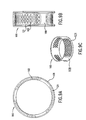
- the gripping pads 58 can be replaced by a perforated suction ring 100, having an outer surface 104 with a plurality of holes 102.
- Independently controllable sources of suction and compressed air are provided to gripper portions 54', 56', which can be moved close together or apart along the steering/elongation portion 52, as described above with reference to Fig. 3 .
- suction is applied to the surrounding tissue through holes 102.
- Holes 102 are designed to distribute the suction over a large area of tissue, so that the traction force generated is increased.
- a suction ring 100 with multiple holes 102 also reduces the chances that holes 102 will be clogged by the tissue, or other debris or contaminants.
- provisions can be made to eject pressurized air or a liquid from holes 102, to force any contaminants out of holes 102.
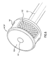
- Suction ring 100 also defines a buffer area, or plenum 101 disposed between the perforated outer surface 104 and the suction connection duct 33, as shown in Fig. 6 .
- Plenum 101 is used to separate the suction duct 33 from the holes 102 on suction ring 100, so that suction is distributed to a larger area of tissue, and clogging of the vacuum supply is prevented.
- Plenum 101 can be, .for example, an enclosed toroidal volume between surface 104 and the center of suction ring 100.
- Plenum 101 may also be divided in non-communicating portions, each connected to a different section of suction ring 100.
- An additional perforated screen can be placed under the surface of suction ring 100.
- This additional screen has holes smaller than holes 102, and acts as a filter to further prevent clogging of duct 33.
- Holes 102 can have a size optimized to maximize suction, while the holes of the additional screen are optimized to stop contaminants.
- the push-pull wires used to control turning and elongation of the catheter travel across at least one of the suction rings 100 before reaching the distal portion 4 of catheter 2.
- the wires must be insulated from the suction source, to prevent vacuum leaks.
- the wires 38 could pass through a passage 120 drilled through suction ring 100, sealed from the portions connected to the suction.
- wires 38 could pass through a sealed tube crossing plenum 101.
- holes 102 do not have to be uniformly distributed around the outer surface 104 of perforated suction ring 100.
- the holes can be grouped in perforated sectors 106 separated by sectors 108 that are not perforated. Sectors 106 may be connected to separate sources of suction, so that if one of the sectors becomes detached from the tissue, the remaining sectors will not be adversely affected, and will continue to apply full suction to the portions of tissue to which they are attached.
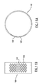
- holes 102 can have a diameter of approximately 1,016 mm, and sectors 106 can extend for approximately 85 degrees of arc, and can be equally spaced around the circumference of suction ring 100.
- holes 102' having a different size can be utilized on suction ring 100.
- holes of a diameter of about 0,508 mm can be formed.
- the size of the holes is optimized to obtain the best suction without excessive clogging. Smaller and more numerous holes tend to grip better the tissue, but clog more easily. Fewer larger holes clog less, but also tend to provide less traction on the tissue. Different sizes of holes can be used in all the configurations of suction ring 100 described here.
- portions of suction ring 100 having holes 102 can be recessed with respect to the rest of the outer surface 104 of suction ring 100.
- recessed portions 121 have a plurality of holes 102 to apply suction to the surrounding tissue.
- the remaining sectors 108 are not perforated.
- the purpose of this design is to obtain a configuration of the suction holes 102 that increases traction by drawing portions of the body tissue in recessed portions 121.
- the recessed pattern of Fig. 9 could be made with different size holes, and could encompass different portions of suction ring 100.
- Fig. 10 shows a configuration of suction ring 100 that is especially advantageous when the body cavity is inflated with a gas, to facilitate visual inspection and passage of medical instruments.
- a gas When a gas is forced in the cavity, such as the colon, it passes around the catheter, and tends to detach portions of the outer surface of suction ring 100 from the surrounding tissue. If a portion of perforated suction ring 100 is detached, the rest of suction ring 100 also is likely to become detached from the tissue, especially if outer surface 104 is uniformly perforated.
- Axial ridges 122 assist in the formation of folds in the tissue surrounding the suction ring 100. The gas forced past suction ring 100 can thus flow in a passage formed by the tissue folds, so that sectors 106 remain attached and keep the suction ring 100 in place.
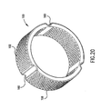
- FIG 20 shows another design that allows passage of gases forced through the cavity.
- Suction ring 100 includes perforated sectors 106 separated by grooves 160. Grooves 160 provide a channel for flowing gases, while perforated sectors 106 remain attached to the surrounding tissue.
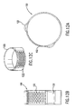
- Fig. 11 shows one example of such application, where a perforated sector 106 extends over an arc of approximately 85 deg., and the rest of suction ring 100 is not perforated.
- the pattern and size of holes 102 can be optimized as desired.
- various features also described above can be included in this design, such as axial ridges 122 shown in Fig. 12 , and a recessed construction of perforated sector 106, shown in Fig. 13 . As before, the purpose of these features is to maximize traction and prevent separation of the entire suction ring 100 from the body cavity tissue.
- Fig. 14 shows a further embodiment of the suction ring 100, where the perforated sector 106 is recessed, and is further surrounded by peripheral ridges 126.
- Peripheral ridges 126 are disposed around the recess 124, and protrude above the outer surface 104 of suction ring 100.
- Peripheral ridges 126 act as a seal that separates the portion of cavity tissue on which perforated sector 106 applies a suction, and the rest of the cavity tissue. In this manner, fluids can flow through the body cavity while the catheter 2 is inserted in the body cavity. The flow can pass between the non perforated sectors 108 of suction ring 100 and the body tissue, while perforated sector 106 together with peripheral ridges 126 maintains a suction against the tissue, and is thus anchored in place.
- suction can be applied to the tissue by slots 132, rather than by round holes 102 described above.
- Slots 132 can be used with any of the configurations described, and can be disposed perpendicular to the relative motion of catheter 2, as shown in Fig. 15b .
- suction ring 100 The several configurations of suction ring 100 are especially well suited for use in conjunction with the proximal and distal gripper portions 54,56 shown in Fig. 3 . However, the same configurations can also be successfully utilized to maximize the traction generated by gripping pads 24 shown in Fig. 1 .
- the traction force that can be generated by the propulsion sections of catheter 2 can be increased by increasing the folds and undulations of the cavity tissue in contact with the suction ring 100, thus generating an interference between the tissue of the inner surface of the body cavity and fixed protrusions of the gripping pads 24, 58.
- suction can be used to draw some tissue in holes, slots or between protrusions formed on suction ring 100. Folds in the tissue then interact with the edges of these structures to generate a force opposing the relative motion between the tissue and suction ring 100 greater than would be possible if the two were simply sliding past each other.
- Fig. 16 shows one possible exemplary embodiment utilizing this principle.
- Tissue 200 of the inner surface of a body cavity is partially drawn inside hole 102 formed in perforated sector 106 of suction ring 100.
- a force F A resisting the relative motion is applied by the portion of tissue 200 that is drawn by suction inside hole 102.
- means can be employed to urge the portion of tissue 200 drawn within hole 102 against the perimeter of hole 102.
- inflatable parts 150 could be inflated, as shown by dashed line 152, to hold tissue 200.
- tissue 200 can be trapped between a sleeve 153 and the perimeter of hole 102.
- sleeve 153 can be concentric with the suction ring 100, and be rotatable or translatable just inside of outer surface 104.
- protrusions extend from the surface of suction ring 100 to interact with the tissue that is drawn between the protrusions by suction.
- the protrusions can be, for example, ridges 136 disposed in a substantially circumferential direction around suction ring 100.
- Suction holes 102 can be disposed between the ridges 136, or even on the raised sides of the ridges 136.
- suction ring 100 can have a "soap dish" surface construction, where a plurality of studs 138 extend from the outer surface, and are interspersed with suction holes 102.
- Fig. 18 This embodiment is shown in Fig. 18 .
- the studs can be staggered in the direction of relative movement.
- the designs shown in Figs. 17 and 18 take advantage of the same mechanism described with reference to Fig. 16 .
- the force exerted by gripper portions 54, 56 can also be varied by changing the axial length of suction ring 100, and the number of rows of holes 102.
- Figure 21 a shows a suction ring 100' having two additional rows of holes 102, in the axial direction of the catheter.
- Figure 21 b shows the same suction ring 100' used in a gripper portion 54, 56, to generate a greater force.
- a common procedure in endoscopy is the examination of the colon and removal of polyps present in the colon.
- a vision light tool (VLT) is inserted into the steering catheter 2 and is secured to the end of the catheter 2.
- Catheter 2 is then inserted into the rectum using a rigid sheath 20.
- the catheter 2 is then driven through the intestine towards the cecum while being guided and controlled by a control unit 34.
- control unit 34 includes a monitor through which the operator can view what is being transmitted by the VLT, so that he can drive the catheter forward or backwards while simultaneously steering it.
- the propulsion section was able to resist a pulling force of approximately 1,13 kg while remaining attached in position in a colon by suction.
- the device After reaching the cecum, the device is then slowly pulled back from the cecum to the rectum, as the interior of the intestine is inspected.
- a suction polypectomy device When a polyp is sighted, a suction polypectomy device is inserted into the catheter until it protrudes from the distal end 4 of catheter 2, and is seen on the monitor by the operator.
- the suction polypectomy tool is steered to the polyp, and the polyp is excised and withdrawn by vacuum through the suction channel of the polypectomy tool. Additional tools can be introduced and brought into position at the site of interest rapidly and easily through working channel 10, because catheter 2 maintains access to the operation site while various tools are withdrawn and inserted back into the catheter.
- the various diagnostic and therapeutic tools used in endoscopy are positioned accurately with respect to the body cavity by moving the distal end 4 of the catheter 2 with the steering section 36, or with the steering/propulsion section 50.
- the endoscopic tools can be positioned accurately by using a separate positioning system, which could include push-pull wires 72 similar to those shown in Figure 2 , or a system including inflatable bellows, linear actuators, or a combination of these devices.
- many components of the catheter introducer system are disposable, thus assuring a high degree of sterility to the device.
- the flexible tube of catheter 2 can be disposable, as well as various portions of the endoscope tools 8 used within working channel 10.
- the catheter introducer system of the present invention could be used to navigate within body cavities other than the GI tract.
- air passages or blood vessels could be explored using this system.
- an outer diameter of the device would have to be less than about 2mm.
Landscapes
- Health & Medical Sciences (AREA)
- Life Sciences & Earth Sciences (AREA)
- Surgery (AREA)
- Biomedical Technology (AREA)
- Medical Informatics (AREA)
- Optics & Photonics (AREA)
- Pathology (AREA)
- Radiology & Medical Imaging (AREA)
- Biophysics (AREA)
- Engineering & Computer Science (AREA)
- Physics & Mathematics (AREA)
- Heart & Thoracic Surgery (AREA)
- Nuclear Medicine, Radiotherapy & Molecular Imaging (AREA)
- Molecular Biology (AREA)
- Animal Behavior & Ethology (AREA)
- General Health & Medical Sciences (AREA)
- Public Health (AREA)
- Veterinary Medicine (AREA)
- Gastroenterology & Hepatology (AREA)
- Media Introduction/Drainage Providing Device (AREA)
Abstract
Description
- The present invention relates to a device for performing endoscopy through a catheter introducer system. In particular, the present invention relates to a catheter introducer system for endoscopy designed to reach the cecum portion of the gastrointestinal tract.
- Endoscopy has become an increasingly important tool in diagnosing and in treating ailments of the gastrointestinal tract, also referred to as the GI tract. Typical endoscopes are essentially formed by a somewhat flexible tube that is pushed through the GI tract, after being introduced in the body cavity starting from the rectum or starting from the esophagus. The endoscope has a steerable tip to facilitate navigation through the GI tract, and typically has to be sufficiently stiff so that it can be pushed further along the body cavity. The tip of the endoscope that is introduced in the GI tract can be outfitted with several devices, most notably an illumination device and a vision device, such as a vision integrated circuit, so that the operator of the endoscope can observe the interior of the GI tract and maneuver the endoscope in the proper position.
- Once the endoscope is in position, other tools attached to the endoscope or inserted through the endoscope can be brought to the proper position in the GI tract. Various procedures can then be carried out, such as removing polyps, performing sutures, irrigation, suction, and removing other tissues. The various tools that are used together with the endoscope can be either inserted separately in the GI tract and placed in the proper position independently, or may travel in a working channel of the endoscope, so that once the endoscope is positioned at the desired location in the GI tract, the tools inserted in the endoscope will also easily reach that position.
- Endoscopes or other smaller similar devices can also be used to explore other body cavities, for example airways or blood vessels. These probes must be small to fit in the smaller cavities, and care must be taken to avoid damage to the more fragile membranes lining these cavities.
- Current state of the art endoscopes are very capable devices, and endoscopy has been very successful in diagnostic and therapeutic applications with the use of current endoscopes and the current arsenal of tools that can be inserted through the working channel of the endoscope, or can be attached to the outside of the endoscope. However, current endoscope technology has limitations and drawbacks. One of the greatest drawbacks of current endoscopes is that the working channel is small. The working channel is small relative to overall diameter of the endoscope, and is further limited by the space taken up by vision, irrigation, suction, light, and control cabling mechanisms that are part of the endoscope and are required to control the endoscope. Thus there is a very small area left for other tools to be introduced through the endoscope.
- Current endoscopes are also difficult to maneuver, particularly when the endoscope has to be pushed all the way to a far portion of the intestine, such as the cecum, located at the beginning portion of the large intestine. Currently, reaching the cecum requires training, skill, luck and trial and error on the part of the operator. Current endoscopes have to be maneuvered by pushing them inside the gastrointestinal tract, while steering the far end inside the body cavity. This situation creates an inherently unstable condition, where a long tube is being pushed through a narrow cavity. This requires the endoscope tube to be rather rigid, resulting in discomfort to the patient as the endoscope is maneuvered. Because of this, the patient often must be sedated.
- Once the cecum has been reached, additional tools still have to be navigated through the body to reach the location, and if the endoscope is withdrawn from that location to make room for other tools, access has to be reestablished using the same complicated procedure. Current endoscopes tend to be reusable because of the high cost of their components, and thus require thorough cleaning to sterilize them. Sterilization can be difficult to guarantee, and in many instances a disposable device would be preferable.
- Accordingly, there is a need for an improved type of endoscope with a introducer system that obviates some of the drawbacks of currently known endoscopes.
-
US Patent 5 243 967 to Hibino discloses an endoscope system that includes an endoscope comprising a moving unit with elastic actuators, a bending section, and a control unit. The endoscope movement is controlled by balloons being sequentially inflated and deflated. -
US Patent 4 447 227 discloses a catheter with two gripping portions located in proximity of the distal end; each of the gripping portions comprises a number of suction elements in fluid connection with an external vacuum source and arranged to stabilise the catheter within a body cavity. - The present invention is directed to a catheter introducer system for endoscopy that substantially obviates one or more of the problems due to limitations and disadvantages of the related art, and that can be used more easily and with less discomfort to the patient.
- This problem is solved by catheter introducer systems according to
claim 1 and claim 24 of the present invention. Advantageous embodiments of the present invention are claimed in the dependent claims. - To achieve these and other advantages and in accordance with the purpose of the invention, as embodied and broadly described, the invention is a catheter introducer system for endoscopy tools, as defined in the
claims - The accompanying drawings are included to provide a further understanding of the invention and are incorporated in and constitute part of the specification, illustrate several embodiments of the invention and together with the description serve to explain the present invention. In the drawings:
-
Figure 1 illustrates a first embodiment of the catheter introducer system for endoscopy according to the invention; -
Figure 2 illustrates a detail of the distal end of the catheter shown inFigure 1 ; -
Figure 3 illustrates a portion of a second embodiment of the catheter introducer system according to the invention; -
Figure 4 illustrates a portion of another embodiment of the catheter introducer system according to the invention; -
Figure 5 is a side elevation showing one embodiment of a steering/propulsion section according to the invention; -
Figure 6 is a perspective view showing a detail of one embodiment of a gripper portion; -
Figure 7 is a front and side view of a first embodiment of a suction ring according to the invention; -
Figure 8 is a front, perspective and side view of a second embodiment of a suction ring according to the invention; -
Figure 9 is a front, perspective and side view of a third embodiment of a suction ring according to the invention; -
Figure 10 is a front and side view of a fourth embodiment of a suction ring according to the invention; -
Figure 11 is a front and side view of a fifth embodiment of a suction ring according to the invention; -
Figure 12 is a front, perspective and side view of a sixth embodiment of a suction ring according to the invention; -
Figure 13 is a front and side view of a seventh embodiment of a suction ring according to the invention; -
Figure 14 is a front, perspective and side view of an eight embodiment of a suction ring according to the invention; -
Figure 15 is a front, perspective and side view of a ninth embodiment of a suction ring according to the invention; -
Figure 15b is a top view of a variation of the embodiment shown inFigure 15 . -
Figure 16 is a diagram showing the interaction of body tissue with a suction hole according to one embodiment of the invention; -
Figure 16b is a diagram showing the interaction of body tissue with a suction hole according to another embodiment of the invention; -
Figure 17 is a top and perspective view of a tenth embodiment of a suction ring according to the invention; -
Figure 18 is a top view of an eleventh embodiment of a suction ring according to the invention; -
Figure 19 is a schematic side view showing the steering/propulsion section according to one embodiment of the invention; -
Figure 20 is a perspective view of a twelfth embodiment of a suction ring according to the invention; and -
Figure 21 is a perspective view of a thirteenth embodiment of a suction ring according to the invention. - The catheter introducer system according to the present invention consists of a large catheter having an outer diameter that is customized to fit within the portion of body cavity into which it is to operate, for example the colon, esophagus, or other part of the GI tract. The catheter may be customized to the size of body cavities of individual patients. A steerable tip is included at the distal end of the catheter that is introduced in the body cavity, so that the device can easily travel inside the GI tract or other body cavity that is the subject of the procedure. A propulsion section is also included near the distal end of the catheter, that operates by pulling the distal end through the body cavity, so that the rest of the device is also pulled along. In this manner, a very flexible catheter tube can be used. A more flexible catheter results in less discomfort to the patient, and can thus be made of a larger diameter than a rigid catheter could be made. The patient also does not have to be sedated for this procedure.
- The catheter introducer system has several functions, including navigation and maneuvering in the GI tract, providing light and vision devices to see the areas surrounding the tip of the catheter, providing suction, irrigation and tissue extraction, transporting devices for image acquisition such as optical and ultrasound sensors, and providing a working channel and tool manipulation for various endoscopy tools.
- Because of the design of the catheter according to the present invention, a larger diameter tube can be used, so that a large working channel is provided for introduction and maneuvering of other tools used during endoscopic procedures. The propulsion and steering sections allow the catheter to maneuver easily in the colon, or in other parts of the GI tract, including hard to reach parts such as the cecum. Once the catheter is positioned near the area of the GI tract of interest, it can remain there while various tools are introduced through the working channel, and thus access to the affected area of the GI tract can easily be accomplished by successive and different tools. Many components of this catheter introducer system are disposable, thus obviating some of the problems due to difficult sterilization procedures.
-
Figure 1 illustrates a first embodiment of the endoscopy delivery catheter according to the invention.Catheter introducer system 1 includes a flexibletubular catheter 2 having a distal end 4 and a proximal end 6. Distal end 4 is the end of the catheter that is introduced in the body cavity, while proximal end 6 is at the opposite end from distal end 4 and remains outside of the body cavity.Flexible catheter 2 is hollow on the inside, thus defining a workingchannel 10 that extends from proximal end 6 to distal end 4.
Since thecatheter 2 is very flexible, it can have a large diameter, so that alarge working channel 10 is provided for introduction and maneuvering ofendoscopy tools 8. - In a preferred embodiment, the working channel is defined by a
sheath 11, which is non-collapsible and thus tends to maintain a circular cross section even when it is bent along its axis.Sheath 11 can also include a coil to help maintain its cross sectional shape. The working channel tends to retain a constant size whensheath 11 is used, so that binding of the tools inserted in the workingchannel 10 is prevented, and the outer surface ofcatheter 2 can be very light and flexible. For example, the working channel can have a diameter of about 14mm, resulting in an outer diameter of the device of about 20mm. - Various types of
tools 8 can be inserted through the workingchannel 10, so that oncecatheter 2 is in position within the body cavity, additional endoscopy tools can quickly and easily reach the area of interest within the GI tract. Any present tool for endoscopy can be adapted for use in the workingchannel 10 ofcatheter 2, and the large cross section of workingchannel 10 opens the possibility of developing new tools and procedures that can improve the function of current devices. In a preferred embodiment, thecatheter portion 2 can be disposable, so that cleanliness and sterilization of the catheter introducer system can be assured. - In addition to
tools 8 that can be introduced through thecatheter introducer system 1, some other devices can be built-in withincatheter 2. For example, avision chip 12 such as a charge coupled device (CCD) or a CMOS andlight source 14 can be built in the catheter, as well as anaccessory 16 that may perform suction, irrigation, or other functions. In addition to avision chip 12, other sensors could be provided on thecatheter introducer system 1. For example, X-ray or ultrasound sensors could be utilized. - In a preferred embodiment,
vision chip 12 andlight source 14 can be part of amodular vision tool 13 that can be detached fromcatheter 2 and replaced. For simplicity,vision tool 13 could snap in place at the front ofcatheter 2, so that electrical or other connections would be made automatically. Using a snap-onvision tool 13 facilitates sterilization of the device, because most components of thecatheter introducer system 1 other thanvision tool 13 could be made disposable. If a CCD is used invision tool 13, only thin wires need to connect the CCD to the proximate end of thecatheter 2.Catheter 2 thus remains flexible and can be manufactured cheaply. If necessary, a fluid supply could be provided to the CCD lens, to clean it of contaminants. - The catheter portion can be provided with a
rectal sheath 20 made of a more rigid material and located at the entrance of the body cavity, for example to prevent the sphincter from compressing and binding the flexible catheter.Sheath 20 is designed to maintain the sphincter in an open position and allow the catheter to move back and forth freely. The sheath may also provide a seal with the outer surface of the catheter. This seal is particularly useful when air is used to inflate the colon, to facilitate the visual inspection. In a further embodiment according to the invention, an active sheath can be used to assist the motion of the catheter, by pushing and pulling on the catheter, for example with an endless screw mechanism, rack and pinion mechanism, or axial and radial actuators of known type. - The catheter introducer system shown in
Figure 1 includes apropulsion section 22 that is located near the distal end 4 ofcatheter 2. Thepropulsion section 22 is designed to pull the portion ofcatheter 2 near it through a body cavity, so that thecatheter 2 can easily navigate through a cavity like the GI tract. Sincepropulsion section 22 is designed to pull from within the body cavity,catheter 2 can be more flexible than would be possible if the catheter were pushed from outside of the body cavity, becausecatheter 2 does not have to transmit the compression loads caused by being pushed. As a result, this device reduces the pain and discomfort felt by the patient, because the device can be made extremely flexible in bending while also having a large diameter.Propulsion system 22 includes several slidinggripping pads 24 that can travel along guides 26 in an axial direction, along the length of thecatheter 2.Gripping pads 24 are located on an outer surface ofcatheter 2, and in one embodiment are distributed evenly around the circumference of thecatheter 2. In the preferred embodiment shown inFigure 1 , grippingpads 24 havesuction ports 25 so that they can attach to the inside surface of the body cavity whenever a vacuum is applied to thesuction port 25. - In a preferred embodiment according to the invention, each one of
gripping pads 24 can move alongguide 26 independently, and the suction applied to each ofsuction ports 25 can be turned on or off independently from that of theother suction ports 25. In a more preferred embodiment, fourgripping pads 24 are provided in four slidingchannels 26, one in each channel, and are spaced about 90° apart from each other around the circumference ofcatheter 2. Opposing pairs ofgripping pads 24 can be coordinated to move and apply suction in unison. - During operation of the
propulsion section 22, thegripping pads 24 move in coordinated manner, gripping, releasing, and sliding to move thecatheter 2 forward and backward. To move forward, for example, approximately half of thepads 24 in a first group located at the first position A in slidingchannel 26 apply a vacuum throughsuction ports 25, so that they become attached to the tissue of the body cavity. At the same time, a second group ofgripping pads 24 is moved to a second position B in slidingchannel 26, without vacuum being applied to theirsuctions ports 25. In this phase air may be expelled through the moving suction ports, to ensure that body tissue does not stick to the movinggripping pads 24. This makes it easier for thegripping pads 24 to slide along the cavity wall. A saline solution or other fluid may also be expelled throughsuction ports 25, to remove any contaminants from the ports. - Once the second group of
gripping pads 24 reaches position B, the vacuum is turned on to theports 25 of those gripping pads, which attach to the tissue of the body cavity. Vacuum is at the same time turned off to the first group ofgripping pads 24 at position A. At thatpoint gripping pads 24 at position B are moved to position A, while maintaining the suction, so that theentire catheter 2 is pulled forward relative to the body cavity tissue by a distance substantially equal to the distance between points A and B of slidingchannel 26. - To move backwards, for example, the same sequence can be carried out in reverse order, so that the group of
gripping pads 24 to which a vacuum is applied are initially moved from point A to point B of the slidingchannel 26, to force thecatheter 2 out of the body cavity. - Vacuum can be applied to
suction ports 25 by turning on and off a connection to avacuum source 31. The sliding movement ofgripping pads 24 andsuction ports 25 within slidingchannel 26 can be performed in a variety of manners, such as by mechanical movement of push-pull wires 30, with force from an inflating bellows, or by activation of linear actuators that respond to electricity or other changes in their operating environment. Movement ofgripping pads 24 within slidingchannel 26 can also be accomplished in other known manners, such as by using shape memory actuators, piezoelectric actuators, or other types of actuators commonly known as artificial muscles. - The application of a vacuum to the
various suction ports 25, movement ofgripping pads 24 within slidingchannels 26, and other control functions can be performed by hand or, in a preferred embodiment, by acontrol unit 34 that automatically coordinates the movement of the individual suctions pads in the sliding channels and application of suction in response to instructions of the operator of the catheter system. The operator, for example, could select movement of the catheter in or out of the cavity, andcontrol unit 34 could operatepropulsion section 22 accordingly.Control unit 34 could include, for example, a memory containing sequences of instructions for movement and application of vacuum by thegripping pads 24, that result in desired movement of thecatheter 2.Control unit 34 could also include an electronic computer to convert those sequences into commands for servo motors, valves, and other actuators that affect the operation ofgripping pads 24, and control supply of vacuum fromvacuum source 31 viaducts 33. - Each of
gripping pads 24 could also have more than onesuction port 25 applying vacuum to the body cavity tissue. A perforated surface could be used instead of an individual port, having a configuration that will be described in detail below, in the context of a perforated suction ring. - In yet another embodiment, different methods for gripping the inside of the body cavity could be used instead of the
suction pads 24. For example, inflatable balloons could grip the tissue of the body cavity when inflated, and could be operated in the same manner as the gripping pads with suction ports. - The catheter introducer system shown in
Figure 1 includes asteering section 36 also located adjacent to the distal end 4 of thecatheter 2. In the preferred embodiment thesteering section 36 is closer to the opening of the distal end 4 of the catheter than thepropulsion section 22. However, the opposite arrangement can also be utilized successfully.Steering section 36 allows an operator to change the direction where distal end 4 is pointed inside the body cavity. In the preferred embodiment shown inFigure 2 , thesteering section 36 comprises a flexible structure, such as a braid ormesh 37, that defines the outer circumferential surface of the tube-like catheter 2.Flexible mesh 37 can be collapsed and can also be extended to several times its collapsed length in a direction along the length of thecatheter 2. In a preferred embodiment,steering section 36 is formed of a flexible mesh tube having similar properties to those of an endoscopic or vascular stent, such as, for example, the Wallstent manufactured by Boston Scientific Corporation. The flexible mesh tube is designed to provide sufficient rigidity to maintain a tube-like shape, while also allowing a change in length of the section. - The tube formed by
flexible mesh 37 can also be bent in a desired direction by stretchingmesh 37 in one circumferential portion while compressing it on the opposite circumferential portion of the tube.Steering section 36 can thus be turned in a selected direction with respect to the center line of thecatheter 2. - The stretching and turning of
flexible mesh 37 can be carried out in a convenient manner by using push-pull cables 38, shown inFig. 2 . Push-pull cables 38 are sufficiently stiff such that they can carry a tension as well as a compression load, and are attached to tip 40 forming the distal end 4 ofcatheter 2.Tip 40 can preferably be made of aluminum or plastic. In a preferred example, push-pull wires 38 are made of NITINOL, which is a super-elastic alloy that resists elastic deformation leading to the formation of kinks. For disposable catheters, thewires 38 can alternatively be made of steel, or other materials that tend to regain their original shape after bending. However, NITINOL wires are preferred for applications wherecatheter 2 is used repeatedly. -
Aluminum tip 40,flexible mesh 37, and push-pull wires 38 are all disposed on the circumference ofcatheter 2, so that workingchannel 10 is left free for introduction of endoscopy tools. Push-pull cables 38 exit the body cavity and exit fromcatheter 2 at the proximal end 6, and can be either manually controlled or can be controlled by thecontrol unit 34.Control unit 34 controls thesteering section 36 in a similar manner as it controls thepropulsion section 22. - When push-
pull wires 38 are moved together, the length of thesteering section 36 changes, and thetip 40 on distal end 4 ofcatheter 2 is pushed further in the body cavity, or is withdrawn partially from the body cavity. If push-pull wires 38 are acted on differentially,steering section 36 can be turned in any direction relative to the length of thecatheter 2.
Sutures 42 can be used to attach push-pull wires 38 at discrete locations on theflexible mesh 37, to control their positioning and to support them, so they can transmit compression forces without buckling. - Devices other than
sutures 42 can be used to hold push-pull wires 38 in position aroundsteering section 36. For example, rigid rings can be fixed at axial locations along thesteering section 36, and the push-pull wires 38 can be attached to the rings, or may be threaded through holes formed in the ring's outer portion. Alternatively, simple clips or loops can be used to tie push-pull wires 38 to specific points ofmesh 37, so the wires can move only in the axial direction. Heat shrink, polyurethane, or other type of low friction flexible cladding can be applied on top offlexible mesh 37 andwires 38 to facilitate insertion and travel of the device within the body cavity. The use of a slippery coating for the catheter makes it easier for thepropulsion section 22 to pull the catheter along the body cavity, and also reduce discomfort to the patient. The low friction coating can also be used on the inside of the cladding, to reduce friction with push-pull wires 38. - In a further embodiment according to the invention, the
steering section 36 can have an outer surface formed by bellows instead of theflexible mesh 37. The bellows can be inflated or deflated to extend or contract, in a direction along the length of thecatheter 2. Bellows can be also extended and contracted by operation of push-pull wires 38, connected to tip 40. In this case, the bellows are used simply as an outer cover for the mechanism of thesteering section 36, similarly to mesh 37. Holes can be formed at the crests of the bellows ridges, to guide and keep in place the push-pull wires 38. The inflation and deflation, or the extension of various bellows sections can be controlled either by hand or by acontrol unit 34. Use of the bellows allows steeringsection 36 to either change its length, or to change the direction where distal end 4 points, in a manner analogous to that described above. - As a further alternative to a mesh or bellows, a coil structure can be used to maintain the push-
pull wires 38 in place, and to give some structural rigidity to thesteering section 36. One or more coils can extend fromtip 40 along the length ofsteering section 36, and can be connected towires 38 with any of the methods described above. -
Sheath 11 defining workingchannel 10 preferably can be attached to tip 40 but not to mesh 37. In this manner, mesh 37 can change length without affecting the shape of the workingchannel 10. -
Figure 3 shows a second embodiment of the catheter introducer system for endoscopy according to the present invention. As shown inFigure 3 , a tube-like catheter 2 defines a workingchannel 10 and has a distal end 4 designed for introduction in the body cavity. As described above, aresilient sheath 11 can be used to define the workingchannel 10. Near the distal end 4 of thecatheter 2, there is a steering/propulsion section 50 that is used both to pull the rest of the catheter along in the body cavity that is being explored, and also to direct the distal end 4 of thecatheter 2 in the desired direction. - Steering/
propulsion section 50 comprises a steering/elongation portion 52 that provides elongation as well as steering functions for the catheter introducer system 1'. For example, steering/elongation portion 52 can be formed by a mesh with push-pull wires similar to the one described inFigure 2 . If the push-pull wires are extended or withdrawn at the same time, steering/elongation portion 52 elongates and distal end 4 of thecatheter 2 is extended further or is withdrawn from the body cavity. If the push-pull wires on one side of steering/elongation portion 52 are extended, while those generally on the opposite side of the steering/elongation portion 52 are withdrawn, the steering/elongation portion 52 will turn towards the withdrawing wires, thus changing the direction in which distal end 4 is pointed. A combination of elongation and turning commands can also be give simultaneously to the steering/elongation portion 52. In a preferred embodiment, threewires 38 are equally spaced at 120° intervals around the circumference of the steering/elongation portion 52, and can provide elongation and steering as described above. - Preferably, steering/
elongation portion 52 is formed of a flexible mesh tube to which are attached push-pull wires 38. This configuration retains a large hollow workingchannel 10 inside the device because the integrated steering and propulsion mechanism takes up little wall thickness. Steering/propulsion section 50 also includes aproximal gripper portion 54 and adistal gripper portion 56 that are respectively positioned at the proximal and distal ends of steering/elongation portion 52. Both the proximal anddistal gripper portions gripping pads 58 that havesuction ports 59 that can selectively apply suction to the surrounding inner surfaces of the body cavity. - In the preferred embodiment,
suction ports 59 are connected to a vacuum system with asource 31 andducts 33, so that when the vacuum is turned on thesuction port 59 will attach to the tissue of the surrounding body cavity. When the vacuum is turned off,suction port 59 releases its grip on the inner surface of the body cavity. In a different embodiment of the invention, one or both of the proximal and distal gripper portions can include other means of attaching themselves to the inner surface of the body cavity, such as inflatable balloons, suction arms, or other known devices. - In a different embodiment, proximal and
distal gripper portions gripping pads 58 withsuction ports 59. Several configurations of perforated suction rings will be described below. - In another embodiment according to the invention, steering/
elongation portion 52 can include, for example, inflatable bellows as described above with reference to thesteering section 36, instead of push-pull wires and flexible mesh. In yet another embodiment according to the invention, the push-pull wires can be replaced bylinear actuators 70 embedded within the flexible structure ofcatheter 2, as shown inFigure 4 and as earlier described. -
Gripper portions catheter 2. The structures within steering/elongation portion 52 must therefore allow this movement. For example, as shown inFigure 19 ,sheath 11 defining workingchannel 10 can be formed by aflexible membrane 150 surrounded bycoils 152. This construction results in asheath 11 that can extend and contract axially while retaining a constant cross section, and provides a smooth inner surface to the workingchannel 10. The tubes that provide suction todistal gripper portion 56 also have to extend and contract axially. This can be achieved, for example, using bellows shapedtubes 154, or using telescopingflexible tubes 156, withseals 158 placed between the telescoping sections. - The catheter introducer system 1' shown in
Figure 3 includes an extremelyflexible catheter 2 and is designed to pull itself along the body cavity where it is introduced, rather than being pushed as is done with traditional endoscopes. The catheter moves in an inchworm fashion by coordinated motion and control of the gripper portions and of the steering/elongation portion. - For example, to move forward, the
proximal gripper portion 54 attaches to the tissue of the body cavity by applying a vacuum tosuction ports 59 of theproximal gripper portion 54. The steering/elongation portion 52 is then extended, so that thedistal gripper portion 56 is pushed further inside the body cavity.Suction ports 59 ofdistal gripper portion 56 then apply a vacuum to the surrounding tissue so as to attach to the tissue, and thesuction ports 59 of theproximal gripper portion 54 stop applying a vacuum. In a preferred embodiment,suction ports 59 can also eject pressurized air to completely release the surrounding tissue. At that point steering/elongation portion 52 is contracted while thedistal gripper portion 56 continues to attach to the surrounding tissue, so that the portion of the catheter behinddistal gripper portion 56 is pulled along inside the body cavity by a distance substantially equal to the contraction distance of steering/elongation portion 52. The process is then repeated until the distal end 4 of thecatheter 2 reaches the desired position inside of the body cavity. - To move backward, the above process is reversed. For example, the
proximal suction gripper 54 attaches to the tissue, while thedistal gripper portion 56 releases the surrounding tissue. Steering/elongation portion 52 is contracted, so that the distal end 4 of thecatheter 2 is withdrawn from the body cavity.Proximal gripper portion 54 then releases the tissue,distal gripper portion 56 attaches to the tissue and the steering/elongation portion 52 is extended, so that the portion of thecatheter 2 behinddistal gripper portion 56 is withdrawn from the body cavity. The order of attachment and release ofgrippers elongation portion 52 cause the catheter to be respectively pulled towards or pushed away from agripper portion - The
catheter 2 can also simply be pulled out of the body cavity by the operator. These steps are repeated until the entirety ofcatheter 2 is extracted from the body cavity. Throughout the operation, steering is achieved by bending the steering/elongatingportion 52 either while the insertion or extraction movement is carried out, or separately while thecatheter 2 remains in position. As shown inFigure 1 , acontrol unit 34 can be used to coordinate the operation of steering/propulsion section 50, such as bending and elongation of steering/elongation portion 52, and application of suction. - The second embodiment according to the invention shown in
Figure 3 also provides alarge working channel 10 through which various endoscopy tools can be inserted and positioned easily in the desired portion of the body cavity. A tool ideally suited for this device is a suction polypectomy device to remove polyps from the intestine. The effectiveness of such device is currently limited by the small working channel of existing endoscopes, but this drawback is resolved by using the catheter introducer system according to the invention. - Several variations can be made to the design of the
gripping pads Figures 1 and3 . These variations are designed to maximize the traction or gripping force exerted by the gripping pads on the surrounding tissue of the body cavity. - In one embodiment shown in
Fig. 5 , thegripping pads 58 can be replaced by aperforated suction ring 100, having anouter surface 104 with a plurality ofholes 102. Independently controllable sources of suction and compressed air are provided to gripper portions 54', 56', which can be moved close together or apart along the steering/elongation portion 52, as described above with reference toFig. 3 . In this example, suction is applied to the surrounding tissue throughholes 102.Holes 102 are designed to distribute the suction over a large area of tissue, so that the traction force generated is increased. Asuction ring 100 withmultiple holes 102 also reduces the chances that holes 102 will be clogged by the tissue, or other debris or contaminants. To further prevent clogging, provisions can be made to eject pressurized air or a liquid fromholes 102, to force any contaminants out ofholes 102. -
Suction ring 100 also defines a buffer area, orplenum 101 disposed between the perforatedouter surface 104 and thesuction connection duct 33, as shown inFig. 6 .Plenum 101 is used to separate thesuction duct 33 from theholes 102 onsuction ring 100, so that suction is distributed to a larger area of tissue, and clogging of the vacuum supply is prevented.Plenum 101 can be, .for example, an enclosed toroidal volume betweensurface 104 and the center ofsuction ring 100.Plenum 101 may also be divided in non-communicating portions, each connected to a different section ofsuction ring 100. - An additional perforated screen can be placed under the surface of
suction ring 100. This additional screen has holes smaller thanholes 102, and acts as a filter to further prevent clogging ofduct 33.Holes 102 can have a size optimized to maximize suction, while the holes of the additional screen are optimized to stop contaminants. - The push-pull wires used to control turning and elongation of the catheter travel across at least one of the suction rings 100 before reaching the distal portion 4 of
catheter 2. Thus the wires must be insulated from the suction source, to prevent vacuum leaks. For example, as shown inFig. 5 , thewires 38 could pass through apassage 120 drilled throughsuction ring 100, sealed from the portions connected to the suction. Alternatively,wires 38 could pass through a sealedtube crossing plenum 101. - In different embodiments, holes 102 do not have to be uniformly distributed around the
outer surface 104 ofperforated suction ring 100. For example, as illustrated inFig. 7 , the holes can be grouped inperforated sectors 106 separated bysectors 108 that are not perforated.Sectors 106 may be connected to separate sources of suction, so that if one of the sectors becomes detached from the tissue, the remaining sectors will not be adversely affected, and will continue to apply full suction to the portions of tissue to which they are attached. In one example, holes 102 can have a diameter of approximately 1,016 mm, andsectors 106 can extend for approximately 85 degrees of arc, and can be equally spaced around the circumference ofsuction ring 100. - As shown in
Fig. 8 , holes 102' having a different size can be utilized onsuction ring 100. For example, holes of a diameter of about 0,508 mm can be formed. The size of the holes is optimized to obtain the best suction without excessive clogging. Smaller and more numerous holes tend to grip better the tissue, but clog more easily. Fewer larger holes clog less, but also tend to provide less traction on the tissue. Different sizes of holes can be used in all the configurations ofsuction ring 100 described here. - In a different embodiment, portions of
suction ring 100 havingholes 102 can be recessed with respect to the rest of theouter surface 104 ofsuction ring 100. For example, as shown inFig. 9 , recessedportions 121 have a plurality ofholes 102 to apply suction to the surrounding tissue. The remainingsectors 108 are not perforated. The purpose of this design is to obtain a configuration of the suction holes 102 that increases traction by drawing portions of the body tissue in recessedportions 121. As the previous configurations, the recessed pattern ofFig. 9 could be made with different size holes, and could encompass different portions ofsuction ring 100. -
Fig. 10 shows a configuration ofsuction ring 100 that is especially advantageous when the body cavity is inflated with a gas, to facilitate visual inspection and passage of medical instruments. When a gas is forced in the cavity, such as the colon, it passes around the catheter, and tends to detach portions of the outer surface ofsuction ring 100 from the surrounding tissue.
If a portion ofperforated suction ring 100 is detached, the rest ofsuction ring 100 also is likely to become detached from the tissue, especially ifouter surface 104 is uniformly perforated.Axial ridges 122 assist in the formation of folds in the tissue surrounding thesuction ring 100. The gas forcedpast suction ring 100 can thus flow in a passage formed by the tissue folds, so thatsectors 106 remain attached and keep thesuction ring 100 in place. -
Figure 20 shows another design that allows passage of gases forced through the cavity.Suction ring 100 includesperforated sectors 106 separated bygrooves 160.Grooves 160 provide a channel for flowing gases, whileperforated sectors 106 remain attached to the surrounding tissue. - In certain applications, it may be desirable to apply suction to only a portion of the circumference of
suction ring 100.Fig. 11 shows one example of such application, where aperforated sector 106 extends over an arc of approximately 85 deg., and the rest ofsuction ring 100 is not perforated. As described above, the pattern and size ofholes 102 can be optimized as desired. In addition, various features also described above can be included in this design, such asaxial ridges 122 shown inFig. 12 , and a recessed construction ofperforated sector 106, shown inFig. 13 . As before, the purpose of these features is to maximize traction and prevent separation of theentire suction ring 100 from the body cavity tissue. -
Fig. 14 shows a further embodiment of thesuction ring 100, where theperforated sector 106 is recessed, and is further surrounded byperipheral ridges 126.Peripheral ridges 126 are disposed around therecess 124, and protrude above theouter surface 104 ofsuction ring 100.Peripheral ridges 126 act as a seal that separates the portion of cavity tissue on which perforatedsector 106 applies a suction, and the rest of the cavity tissue. In this manner, fluids can flow through the body cavity while thecatheter 2 is inserted in the body cavity. The flow can pass between the nonperforated sectors 108 ofsuction ring 100 and the body tissue, whileperforated sector 106 together withperipheral ridges 126 maintains a suction against the tissue, and is thus anchored in place. - As shown in
Fig. 15 , suction can be applied to the tissue byslots 132, rather than byround holes 102 described above.Slots 132 can be used with any of the configurations described, and can be disposed perpendicular to the relative motion ofcatheter 2, as shown inFig. 15b . - The several configurations of
suction ring 100 are especially well suited for use in conjunction with the proximal anddistal gripper portions Fig. 3 . However, the same configurations can also be successfully utilized to maximize the traction generated by grippingpads 24 shown inFig. 1 . - The traction force that can be generated by the propulsion sections of
catheter 2 can be increased by increasing the folds and undulations of the cavity tissue in contact with thesuction ring 100, thus generating an interference between the tissue of the inner surface of the body cavity and fixed protrusions of thegripping pads suction ring 100. Folds in the tissue then interact with the edges of these structures to generate a force opposing the relative motion between the tissue andsuction ring 100 greater than would be possible if the two were simply sliding past each other. -
Fig. 16 shows one possible exemplary embodiment utilizing this principle.Tissue 200 of the inner surface of a body cavity is partially drawn insidehole 102 formed inperforated sector 106 ofsuction ring 100. Assuction ring 100 mounted oncatheter 2 is moved in a relative direction A, a force FA resisting the relative motion is applied by the portion oftissue 200 that is drawn by suction insidehole 102. To further increase this traction force, means can be employed to urge the portion oftissue 200 drawn withinhole 102 against the perimeter ofhole 102. For example,inflatable parts 150 could be inflated, as shown by dashedline 152, to holdtissue 200. - In a different embodiment shown in
Fig. 16b , after being drawn insidehole 102,tissue 200 can be trapped between asleeve 153 and the perimeter ofhole 102. For example,sleeve 153 can be concentric with thesuction ring 100, and be rotatable or translatable just inside ofouter surface 104. - A different exemplary embodiment of a design to increase traction forces is shown in
Figs. 17 and 18 . In this case, protrusions extend from the surface ofsuction ring 100 to interact with the tissue that is drawn between the protrusions by suction. As shown inFig. 17 , the protrusions can be, for example,ridges 136 disposed in a substantially circumferential direction aroundsuction ring 100. Suction holes 102 can be disposed between theridges 136, or even on the raised sides of theridges 136. Instead of ridges,suction ring 100 can have a "soap dish" surface construction, where a plurality ofstuds 138 extend from the outer surface, and are interspersed with suction holes 102. This embodiment is shown inFig. 18 . To maximize the resistance to relative movement between the catheter and the tissue, the studs can be staggered in the direction of relative movement. The designs shown inFigs. 17 and 18 take advantage of the same mechanism described with reference toFig. 16 . - The force exerted by
gripper portions suction ring 100, and the number of rows ofholes 102. For example,Figure 21 a shows a suction ring 100' having two additional rows ofholes 102, in the axial direction of the catheter.Figure 21 b shows the same suction ring 100' used in agripper portion - An example of how the catheter introducer system according to the invention can be used will now be described with reference to
Figures 1 through 3 . A common procedure in endoscopy is the examination of the colon and removal of polyps present in the colon. A vision light tool (VLT) is inserted into thesteering catheter 2 and is secured to the end of thecatheter 2.Catheter 2 is then inserted into the rectum using arigid sheath 20. Thecatheter 2 is then driven through the intestine towards the cecum while being guided and controlled by acontrol unit 34. In one embodiment according to the invention,control unit 34 includes a monitor through which the operator can view what is being transmitted by the VLT, so that he can drive the catheter forward or backwards while simultaneously steering it. During tests, the propulsion section was able to resist a pulling force of approximately 1,13 kg while remaining attached in position in a colon by suction. - After reaching the cecum, the device is then slowly pulled back from the cecum to the rectum, as the interior of the intestine is inspected. When a polyp is sighted, a suction polypectomy device is inserted into the catheter until it protrudes from the distal end 4 of
catheter 2, and is seen on the monitor by the operator. The suction polypectomy tool is steered to the polyp, and the polyp is excised and withdrawn by vacuum through the suction channel of the polypectomy tool. Additional tools can be introduced and brought into position at the site of interest rapidly and easily through workingchannel 10, becausecatheter 2 maintains access to the operation site while various tools are withdrawn and inserted back into the catheter. - In a preferred embodiment according to the invention, the various diagnostic and therapeutic tools used in endoscopy are positioned accurately with respect to the body cavity by moving the distal end 4 of the
catheter 2 with thesteering section 36, or with the steering/propulsion section 50. In a different embodiment, still within the scope of the invention, the endoscopic tools can be positioned accurately by using a separate positioning system, which could include push-pull wires 72 similar to those shown inFigure 2 , or a system including inflatable bellows, linear actuators, or a combination of these devices. Also in a preferred embodiment according to the invention, many components of the catheter introducer system are disposable, thus assuring a high degree of sterility to the device. For example, the flexible tube ofcatheter 2 can be disposable, as well as various portions of theendoscope tools 8 used within workingchannel 10. - As indicated, the catheter introducer system of the present invention could be used to navigate within body cavities other than the GI tract. For example, air passages or blood vessels could be explored using this system. For blood vessels, it would be necessary to reduce the size of the apparatus, and preferably to only use the steering section, to avoid interference with blood flow through the vessel. For example, an outer diameter of the device would have to be less than about 2mm.
Claims (37)
- A self propelling catheter introducer system for exploring a body cavity, comprising:a flexible tubular catheter (2) having a length extending from a distal end (4) for introduction in the cavity to a proximal end (6) opposite the distal end;a tubular working channel (10) formed within the catheter (2), adapted for guiding medical tools along the length of the catheter;a propulsion section (22) of the catheter disposed adjacent the distal end, adapted for pulling the catheter through the cavity;a steering section (36) of the catheter disposed adjacent the distal end, adapted for pointing the distal end in a desired direction; andcontrol means (34) for controlling operation of the propulsion section (22) and the steering section (36)
wherein the propulsion section (22) comprises: a first and a second guide (26);a first sliding gripping pad pad (24) disposed on an outer surface of the catheter, said first sliding gripping pad being movable along the first guide (26) in an axial direction, along the length of the catheter between a first position towards the distal end, and a second position towards the proximal end, adapted for selectively gripping tissue of an inner portion of the cavity by applying suction to the tissue ; anda second sliding gripping pad (24), adapted to selectively grip the inner portion of the cavity by applying suction to the tissue, and movable along the second guide (26) in an axial direction, along the length of the catheter between the first and second positions, independently from the first sliding gripping pad, the second guide (26) being substantially parallel to the first guide (26). - The system according to claim 1, wherein the proximal end (6) defines an opening to introduce the medical tools in the catheter working channel (10).
- The system according to claim 1, wherein the distal end (4) defines an opening allowing the medical tools to operate outside the catheter working channel (10).
- The system according to claim 1, further comprising a light vision tool (13) detachably connected to the distal end of the catheter.
- The system according to claim 1, further comprising a rigid sheath (20) disposed around the tubular catheter (2) at a point of entry of the body cavity, having means to move the tubular catheter axially and rotationally.
- The system according to claim I, wherein a plurality of first and second sliding gripping pads (24) are spaced circumferentially around the catheter.
- The system according to claim 1, wherein the control means (34) is adapted to control movement and suction applied by the first sliding gripping pad (24) and the second sliding gripping pad (24) in response to user inputs.
- The system according to claim 1, wherein the first and second sliding gripping pads (24) include at least one suction port (25).
- The system according to claim 1, comprising two first and two second sliding gripping pads (24) circumferentially spaced around the catheter at equal distances, wherein the two first sliding gripping pads (24) disposed in opposing relationship move and apply suction in unison, independently from the two second sliding gripping pads (24) disposed in opposing relationship that also move and apply suction in unison.
- The system according to claim 1, wherein the first and second sliding gripping pads (24) comprise a perforated suction surface (104) defining a plurality of suction holes (102).
- The system according to claim 10, further comprising a peripheral ridge (136) substantially surrounding the plurality of suction holes (102).
- The system according to claim 10, wherein the perforated suction surface (104) is recessed with respect to the outer surface of the catheter.
- The system according to claim 10, wherein the perforated suction surface (104) extends above the outer surface of the catheter.
- The system according to claim 10, wherein the suction holes (102) have a diameter of between about 0,508 mm and 1,016 mm.
- The system according to claim 1, further comprising a non-collapsible sheath (11) defining the working channel, disposed inside the catheter, extending substantially from the proximal to the distal end.
- The system according to claim 1, wherein the steering section (36) comprises a plurality of push-pull wires (38) secured to the distal end of the catheter, circumferentially disposed along the length of the catheter, adapted to be individually extended and retracted to point the distal end in the desired direction.
- The system according to claim 16, wherein the steering section (36) further comprises a flexible tube-like structure to guide movement of the plurality of push-pull wires (38).
- The system according to claim 17, wherein the flexible tube-like structure is formed of a coil (152).
- The system according to claim 17, wherein the flexible tube-like structure is formed of bellows (154).
- The system according to claim 17, further comprising means to attach the push-pull wires (38) to the flexible structure at discrete points.
- The system according to claim 20, wherein the means to attach comprise sutures (42).
- The system according to claim 1, wherein the steering section (36) comprises a plurality of linear actuators adapted to be independently extended and contracted, disposed circumferentially around the steering section, adapted to point the distal end in the desired direction.
- The system according to claim 1, wherein the steering section (36) comprises bellows that can be extended and contracted in a direction along the length of the catheter, and control wires disposed circumferentially around the catheter to control extension of the bellows, thus pointing the distal end in the desired direction.
- A self propelling catheter introducer system for exploring a body cavity, comprising:a flexible tubular catheter (2) having a length extending from a distal end (4) for introduction in the cavity to a proximal end (6) opposite the distal end;a tubular working channel (10) formed within the catheter (2), adapted for guiding medical tools along the length of the catheter;a propulsion section of the catheter disposed adjacent the distal end, adapted for pulling the catheter through the cavity;a steering/elongation portion (52) of the catheter disposed adjacent the distal end, adapted for pointing the distal end in a desired direction; andcontrol means (34) for controlling operation of the propulsion section and the steering/elongation portion (52);
wherein the steering/elongation portion (52) and the propulsion section are combined in a single steering/propulsion section (50), and
wherein the steering/propulsion section comprises:a distal gripper portion (56) attached to the catheter adjacent the distal end, adapted for selectively gripping by suction and releasing tissue of an inner portion of the cavity;a proximal gripper portion (54) attached to the catheter, disposed furtherfrom the distal end than the distal gripper portion, and adapted forselectively gripping by suction and releasing the tissue of the cavity; andthe steering/elongation portion (52) being disposed between the distal andproximal gripper portions, adapted for changing a relative position of the distal and proximal gripper portions to extend and turn the distal end to the desired direction;wherein the proximal and distal gripper portions (54, 56) each comprise a suction ring (100) having an outer surface defining a plurality of suction holes (102), the suction ring extending circumferentially around the catheter; and wherein the suction ring (100) comprises perforated sectors (106) defining the suction holes (102), and non-perforated sectors (108). - The system according to claim 24, wherein the suction ring (100) has an axial length of about 7,62 mm.
- The system according to claim 24, wherein the suction holes (102) have a diameter of between approximately 0,508 mm and 1,016 mm.
- The system according to claim 24, further comprising grooves (160) separating the perforated sectors (106).
- The system according to claim 24, further comprising axial ridges (122) separating alternating perforated (106) and non-perforated sectors (108).
- The system according to claim 24, wherein the perforated sectors (106) are recessed relative to the outer surface of the suction ring (100).
- The system according to claim 24 wherein the perforated sectors (106) extend above the outer surface of the suction ring (100).
- The system according to claim 24, further comprising a peripheral ridge (126) extending above the outer surface of the suction ring (100), surrounding the perforated sectors (106).
- The system according to claim 24 further comprising a plenum (101) disposed radially inside the outer surface of the suction ring (100).
- The system according to claim 24, wherein the steering/elongation portion (52) comprises a flexible structure extending between the proximal and distal gripper portions (54, 56), and control wires (38) attached to the distal gripper, the control wires (38) being each independently extendable and retractable.
- The system according to claim 33, further comprising sutures (42) securing the control wires (38) to the flexible structure.
- The system according to claim 24, wherein the control means is adapted to provide suction to the proximal and distal gripper portions (54, 56), and to change the relative position of the proximal and distal gripper portions (54, 56) in response to user inputs.
- The system according to claim 24, further comprising a rigid sheath (20) disposed around the tubular catheter, slidable along a length of the tubular catheter.
- The system according to claim 24, further comprising means for urging the tissue of the cavity against a perimeter of the suction holes (102).
Applications Claiming Priority (3)
| Application Number | Priority Date | Filing Date | Title |
|---|---|---|---|
| US09/492,448 US6517477B1 (en) | 2000-01-27 | 2000-01-27 | Catheter introducer system for exploration of body cavities |
| US492448 | 2000-01-27 | ||
| PCT/US2000/032460 WO2001054565A2 (en) | 2000-01-27 | 2000-11-29 | Catheter introducer system for exploration of body cavities |
Publications (2)
| Publication Number | Publication Date |
|---|---|
| EP1255482A2 EP1255482A2 (en) | 2002-11-13 |
| EP1255482B1 true EP1255482B1 (en) | 2010-05-05 |
Family
ID=23956293
Family Applications (1)
| Application Number | Title | Priority Date | Filing Date |
|---|---|---|---|
| EP00983794A Expired - Lifetime EP1255482B1 (en) | 2000-01-27 | 2000-11-29 | Catheter introducer system for exploration of body cavities |
Country Status (8)
| Country | Link |
|---|---|
| US (5) | US6517477B1 (en) |
| EP (1) | EP1255482B1 (en) |
| JP (1) | JP5129914B2 (en) |
| AU (2) | AU2050401A (en) |
| CA (1) | CA2396869A1 (en) |
| DE (1) | DE60044375D1 (en) |
| IL (1) | IL150879A0 (en) |
| WO (1) | WO2001054565A2 (en) |
Families Citing this family (216)
| Publication number | Priority date | Publication date | Assignee | Title |
|---|---|---|---|---|
| US6699179B2 (en) * | 2000-01-27 | 2004-03-02 | Scimed Life Systems, Inc. | Catheter introducer system for exploration of body cavities |
| US6517477B1 (en) | 2000-01-27 | 2003-02-11 | Scimed Life Systems, Inc. | Catheter introducer system for exploration of body cavities |
| US8517923B2 (en) * | 2000-04-03 | 2013-08-27 | Intuitive Surgical Operations, Inc. | Apparatus and methods for facilitating treatment of tissue via improved delivery of energy based and non-energy based modalities |
| US8888688B2 (en) | 2000-04-03 | 2014-11-18 | Intuitive Surgical Operations, Inc. | Connector device for a controllable instrument |
| US6858005B2 (en) * | 2000-04-03 | 2005-02-22 | Neo Guide Systems, Inc. | Tendon-driven endoscope and methods of insertion |
| US6610007B2 (en) * | 2000-04-03 | 2003-08-26 | Neoguide Systems, Inc. | Steerable segmented endoscope and method of insertion |
| US6468203B2 (en) | 2000-04-03 | 2002-10-22 | Neoguide Systems, Inc. | Steerable endoscope and improved method of insertion |
| EP1662972A4 (en) * | 2000-04-03 | 2010-08-25 | Intuitive Surgical Inc | Activated polymer articulated instruments and methods of insertion |
| US6793621B2 (en) * | 2001-03-08 | 2004-09-21 | Atropos Limited | Colonic overtube |
| KR100452754B1 (en) * | 2001-06-28 | 2004-10-12 | 주식회사세운메디칼상사 | Apparatus for inserting guide wire for use in catheter |
| US20060201351A1 (en) * | 2001-07-02 | 2006-09-14 | Gi View Ltd. | Self-propelled imaging system |
| US6605078B2 (en) * | 2001-11-26 | 2003-08-12 | Scimed Life Systems, Inc. | Full thickness resection device |
| HUP0500442A2 (en) | 2001-12-06 | 2005-08-29 | Smith & Nephew, Inc. | In-situ oxidized textured surfaces for prosthetic devices and method of making same |
| JP2005514145A (en) | 2002-01-09 | 2005-05-19 | ネオガイド システムズ, インコーポレイテッド | Apparatus and method for endoscopic colectomy |
| US20050085829A1 (en) * | 2002-05-17 | 2005-04-21 | Esophyx, Inc. | Transoral endoscopic gastroesophageal flap valve restoration device, assembly, system and method |
| KR100471653B1 (en) * | 2002-08-06 | 2005-03-10 | 한국과학기술연구원 | Endoscope system |
| AU2003262896B2 (en) | 2002-08-24 | 2008-08-07 | Subramaniam C. Krishnan | Method and apparatus for locating the fossa ovalis and performing transseptal puncture |
| ES2291670T3 (en) * | 2002-10-03 | 2008-03-01 | Etview Ltd. | ENDOTRAQUEAL TUBE WITH IMAGE SENSOR. |
| US6872178B2 (en) * | 2002-11-18 | 2005-03-29 | Andrew Mark Weinberg | Colonoscope apparatus and method |
| WO2004058041A2 (en) * | 2002-12-26 | 2004-07-15 | Given Imaging Ltd. | Immobilizable in vivo sensing device |
| US8882657B2 (en) * | 2003-03-07 | 2014-11-11 | Intuitive Surgical Operations, Inc. | Instrument having radio frequency identification systems and methods for use |
| US6971990B2 (en) * | 2003-04-14 | 2005-12-06 | Troy J. Ziegler | Propulsion mechanism for endoscopic systems |
| US7736300B2 (en) | 2003-04-14 | 2010-06-15 | Softscope Medical Technologies, Inc. | Self-propellable apparatus and method |
| US7833176B2 (en) * | 2003-08-13 | 2010-11-16 | G. I. View Ltd. | Pressure-propelled system for body lumen |
| US20050036059A1 (en) * | 2003-08-13 | 2005-02-17 | Benad Goldwasser | Ingestible imaging system |
| US20050038318A1 (en) * | 2003-08-13 | 2005-02-17 | Benad Goldwasser | Gastrointestinal tool over guidewire |
| US8340779B2 (en) | 2003-08-29 | 2012-12-25 | Medtronic, Inc. | Percutaneous flat lead introducer |
| WO2005046461A1 (en) * | 2003-11-07 | 2005-05-26 | Carnegie Mellon University | Robot for minimally invasive interventions |
| US7087011B2 (en) * | 2003-12-30 | 2006-08-08 | Gi View Ltd. | Gastrointestinal system with traction member |
| US8702597B2 (en) * | 2003-12-31 | 2014-04-22 | Given Imaging Ltd. | Immobilizable in-vivo imager with moveable focusing mechanism |
| US7553323B1 (en) | 2004-01-08 | 2009-06-30 | Perez Juan I | Steerable endovascular graft delivery system |
| US8419678B2 (en) | 2004-01-09 | 2013-04-16 | G.I. View Ltd. | Pressure-propelled system for body lumen |
| ES2546355T3 (en) * | 2004-01-09 | 2015-09-22 | G.I. View Ltd. | Pressure propelled system for body light |
| US7635345B2 (en) * | 2004-01-09 | 2009-12-22 | G. I. View Ltd. | Pressure-propelled system for body lumen |
| US7635346B2 (en) * | 2004-01-09 | 2009-12-22 | G. I. View Ltd. | Pressure-propelled system for body lumen |
| CN103142199B (en) * | 2004-02-09 | 2016-09-28 | 智能医疗系统有限公司 | Endoscope assembly |
| US7708689B2 (en) * | 2004-05-12 | 2010-05-04 | Linvatec Corporation | Endoscope and related system |
| WO2005110186A2 (en) | 2004-05-14 | 2005-11-24 | G.I. View Ltd. | Omnidirectional and forward-looking imaging device |
| US7632265B2 (en) | 2004-05-28 | 2009-12-15 | St. Jude Medical, Atrial Fibrillation Division, Inc. | Radio frequency ablation servo catheter and method |
| US7974674B2 (en) * | 2004-05-28 | 2011-07-05 | St. Jude Medical, Atrial Fibrillation Division, Inc. | Robotic surgical system and method for surface modeling |
| US10863945B2 (en) * | 2004-05-28 | 2020-12-15 | St. Jude Medical, Atrial Fibrillation Division, Inc. | Robotic surgical system with contact sensing feature |
| US8755864B2 (en) | 2004-05-28 | 2014-06-17 | St. Jude Medical, Atrial Fibrillation Division, Inc. | Robotic surgical system and method for diagnostic data mapping |
| US10258285B2 (en) * | 2004-05-28 | 2019-04-16 | St. Jude Medical, Atrial Fibrillation Division, Inc. | Robotic surgical system and method for automated creation of ablation lesions |
| US9782130B2 (en) * | 2004-05-28 | 2017-10-10 | St. Jude Medical, Atrial Fibrillation Division, Inc. | Robotic surgical system |
| US8528565B2 (en) | 2004-05-28 | 2013-09-10 | St. Jude Medical, Atrial Fibrillation Division, Inc. | Robotic surgical system and method for automated therapy delivery |
| EP1778054B1 (en) | 2004-06-25 | 2013-08-07 | Carnegie Mellon University | Steerable, follow the leader device |
| NL1026884C2 (en) * | 2004-08-19 | 2006-02-21 | Univ Delft Tech | Instrument comprising a cable or hose provided with a propulsion member. |
| US7473278B2 (en) | 2004-09-16 | 2009-01-06 | Smith & Nephew, Inc. | Method of surface oxidizing zirconium and zirconium alloys and resulting product |
| US7771411B2 (en) | 2004-09-24 | 2010-08-10 | Syntheon, Llc | Methods for operating a selective stiffening catheter |
| WO2006050493A2 (en) * | 2004-11-03 | 2006-05-11 | The Regents Of The University Of Michigan | Biodegradable implant for intertransverse process fusion |
| JP4520280B2 (en) * | 2004-11-12 | 2010-08-04 | Hoya株式会社 | Tracheal tubescope |
| US20060135847A1 (en) * | 2004-12-22 | 2006-06-22 | Zoom Medical, L.L.C. | Endoscope guiding device |
| WO2006070356A2 (en) * | 2004-12-30 | 2006-07-06 | Given Imaging Ltd. | Device, system, and method for adaptive imaging |
| ES2461602T3 (en) | 2005-01-06 | 2014-05-20 | G.I. View Ltd. | Gastrointestinal instrument on guiding element |
| US20060173241A1 (en) * | 2005-01-14 | 2006-08-03 | Pentax Corporation | Front end structure of endoscope |
| JP2006192087A (en) * | 2005-01-14 | 2006-07-27 | Pentax Corp | Distal end part of endoscope to be inserted into large intestine |
| JP2006192088A (en) * | 2005-01-14 | 2006-07-27 | Pentax Corp | Distal end part of endoscope to be inserted into large intestine |
| JP4611756B2 (en) * | 2005-01-14 | 2011-01-12 | Hoya株式会社 | End of endoscope for large intestine insertion |
| JP2006192091A (en) * | 2005-01-14 | 2006-07-27 | Pentax Corp | Distal end part of endoscope to be inserted into large intestine |
| JP4648712B2 (en) * | 2005-01-14 | 2011-03-09 | Hoya株式会社 | End of endoscope for large intestine insertion |
| US20080091063A1 (en) * | 2005-02-07 | 2008-04-17 | Smart Medical Systems, Ltd. | Endoscope assembly |
| WO2006085316A2 (en) | 2005-02-10 | 2006-08-17 | G.I. View Ltd. | Advancement techniques for gastrointestinal tool with guiding element |
| US20060235458A1 (en) * | 2005-04-15 | 2006-10-19 | Amir Belson | Instruments having an external working channel |
| US7591784B2 (en) * | 2005-04-26 | 2009-09-22 | St. Jude Medical, Atrial Fibrillation Division, Inc. | Bi-directional handle for a catheter |
| US20060259010A1 (en) * | 2005-05-13 | 2006-11-16 | David Stefanchik | Feeding tube |
| US20060258904A1 (en) * | 2005-05-13 | 2006-11-16 | David Stefanchik | Feeding tube and track |
| US8155910B2 (en) | 2005-05-27 | 2012-04-10 | St. Jude Medical, Atrial Fibrillation Divison, Inc. | Robotically controlled catheter and method of its calibration |
| DE602006019869D1 (en) * | 2005-06-09 | 2011-03-10 | Medtronic Inc | IMPLANTABLE MEDICAL MANAGEMENT |
| ATE537870T1 (en) | 2005-06-09 | 2012-01-15 | Medtronic Inc | PERIPHERAL NERVOUS FIELD STIMULATION AND SPINAL CORD STIMULATION |
| US7792591B2 (en) * | 2005-06-09 | 2010-09-07 | Medtronic, Inc. | Introducer for therapy delivery elements |
| EP1904173B8 (en) * | 2005-06-09 | 2016-06-08 | Medtronic, Inc. | Implantable medical device with electrodes on multiple housing surfaces |
| US8620435B2 (en) | 2005-06-09 | 2013-12-31 | Medtronic, Inc. | Combination therapy including peripheral nerve field stimulation |
| JP4756943B2 (en) | 2005-07-22 | 2011-08-24 | オリンパス株式会社 | Endoscopic suturing device |
| US9241614B2 (en) * | 2005-08-01 | 2016-01-26 | G.I. View Ltd. | Tools for use in esophagus |
| WO2007015240A2 (en) * | 2005-08-01 | 2007-02-08 | G.I. View Ltd. | Tools for use in small intestine |
| US8430809B2 (en) * | 2005-08-01 | 2013-04-30 | G. I View Ltd. | Capsule for use in small intestine |
| US9061118B2 (en) * | 2005-08-11 | 2015-06-23 | Technion Research & Development Foundation Ltd. | Tip propelled device for motion through a passage |
| EP1931237A2 (en) * | 2005-09-14 | 2008-06-18 | Neoguide Systems, Inc. | Methods and apparatus for performing transluminal and other procedures |
| US7753902B1 (en) * | 2005-11-17 | 2010-07-13 | Hebah Noshy Mansour | Methods and devices for tissue monitoring |
| EP1956962B1 (en) | 2005-11-22 | 2020-09-16 | Intuitive Surgical Operations, Inc. | System for determining the shape of a bendable instrument |
| JP2009517608A (en) * | 2005-11-23 | 2009-04-30 | ネオガイド システムズ, インコーポレイテッド | Non-metallic multi-strand control cable for steerable devices |
| DE102005057479A1 (en) * | 2005-11-30 | 2007-05-31 | Philipps-Universität Marburg | Arrangement for guidance of instrument within hollow chamber, has fixing means, at distance from each other, which can be activated in form that each fixing means is implemented independent from other |
| PT1803389E (en) * | 2005-12-28 | 2011-04-21 | Era Endoscopy S R L | Self-propelled endoscopic device |
| US9155451B2 (en) | 2006-03-02 | 2015-10-13 | Syntheon, Llc | Variably flexible insertion device and method for variably flexing an insertion device |
| US7988621B2 (en) | 2006-08-10 | 2011-08-02 | Syntheon, Llc | Torque-transmitting, variably-flexible, corrugated insertion device and method for transmitting torque and variably flexing a corrugated insertion device |
| US8092374B2 (en) | 2006-03-02 | 2012-01-10 | Kevin Smith | Variably flexible insertion device and method for variably flexing an insertion device |
| US8556804B2 (en) * | 2006-05-22 | 2013-10-15 | Syntheon, Llc | Torque-transmitting, variably flexible insertion device and method for transmitting torque and variably flexing an insertion device |
| US9814372B2 (en) | 2007-06-27 | 2017-11-14 | Syntheon, Llc | Torque-transmitting, variably-flexible, locking insertion device and method for operating the insertion device |
| US10123683B2 (en) | 2006-03-02 | 2018-11-13 | Syntheon, Llc | Variably flexible insertion device and method for variably flexing an insertion device |
| WO2007123770A2 (en) | 2006-03-31 | 2007-11-01 | Automated Medical Instruments, Inc. | System and method for advancing, orienting, and immobilizing on internal body tissue a catheter or therapeutic device |
| JP5116985B2 (en) * | 2006-04-13 | 2013-01-09 | 富士フイルム株式会社 | Endoscope |
| US8568299B2 (en) | 2006-05-19 | 2013-10-29 | Intuitive Surgical Operations, Inc. | Methods and apparatus for displaying three-dimensional orientation of a steerable distal tip of an endoscope |
| US20080097152A1 (en) * | 2006-07-20 | 2008-04-24 | David Stefanchik | Braided endoscope accessories |
| CN101528111B (en) | 2006-08-14 | 2012-04-04 | 卡迪欧机器人技术股份有限公司 | Steerable multi-linked device having multiple working ports |
| WO2008045877A2 (en) * | 2006-10-10 | 2008-04-17 | St. Jude Medical, Atrial Fibrillation Division, Inc. | Electrode tip and ablation system |
| US8012086B2 (en) * | 2006-10-19 | 2011-09-06 | Ethicon Endo-Surgery, Inc. | Sterile transcolonic access device |
| AU2007308935B2 (en) | 2006-10-24 | 2014-07-17 | Carnegie Mellon University | Steerable multi-linked device having a modular link assembly |
| US20080103360A1 (en) * | 2006-11-01 | 2008-05-01 | Boris Shtul | Endoscopic device insertable into a body cavity and movable in a predetermined direction, and method of moving the endoscopic device in the body cavity |
| TW200824643A (en) * | 2006-12-13 | 2008-06-16 | Chieh-Hsiao Chen | Guiding stylet apparatus |
| WO2008099389A2 (en) * | 2007-02-12 | 2008-08-21 | Technion Research & Development Foundation Ltd. | Inflatable balloon device and applications |
| US7655004B2 (en) | 2007-02-15 | 2010-02-02 | Ethicon Endo-Surgery, Inc. | Electroporation ablation apparatus, system, and method |
| WO2008121466A2 (en) | 2007-02-27 | 2008-10-09 | Carnegie Mellon University | A multi-linked device having a reinforcing member |
| US8100930B2 (en) | 2007-03-30 | 2012-01-24 | Ethicon Endo-Surgery, Inc. | Tissue moving surgical device |
| US8142356B2 (en) | 2007-03-30 | 2012-03-27 | Ethicon Endo-Surgery, Inc. | Method of manipulating tissue |
| US8979837B2 (en) | 2007-04-04 | 2015-03-17 | St. Jude Medical, Atrial Fibrillation Division, Inc. | Flexible tip catheter with extended fluid lumen |
| US8764742B2 (en) | 2007-04-04 | 2014-07-01 | St. Jude Medical, Atrial Fibrillation Division, Inc. | Irrigated catheter |
| US8517999B2 (en) | 2007-04-04 | 2013-08-27 | St. Jude Medical, Atrial Fibrillation Division, Inc. | Irrigated catheter with improved fluid flow |
| JP2008259701A (en) * | 2007-04-12 | 2008-10-30 | Olympus Corp | Apparatus inserted into living body |
| US20080262294A1 (en) * | 2007-04-20 | 2008-10-23 | Usgi Medical, Inc. | Endoscopic system with disposable sheath |
| US8398540B2 (en) * | 2007-05-10 | 2013-03-19 | Technion Research & Development Foundation Ltd. | Semi disposable endoscope |
| US10220187B2 (en) | 2010-06-16 | 2019-03-05 | St. Jude Medical, Llc | Ablation catheter having flexible tip with multiple flexible electrode segments |
| US8974454B2 (en) | 2009-12-31 | 2015-03-10 | St. Jude Medical, Atrial Fibrillation Division, Inc. | Kit for non-invasive electrophysiology procedures and method of its use |
| US11395694B2 (en) * | 2009-05-07 | 2022-07-26 | St. Jude Medical, Llc | Irrigated ablation catheter with multiple segmented ablation electrodes |
| US8157727B2 (en) * | 2007-07-16 | 2012-04-17 | Ethicon Endo-Surgery, Inc. | Surgical methods and devices with movement assistance |
| JP2009055955A (en) * | 2007-08-29 | 2009-03-19 | Olympus Medical Systems Corp | Endoscope apparatus |
| US20100191264A1 (en) | 2007-09-21 | 2010-07-29 | Cvd Devices, Llc | Devices, systems and methods for diagnosing and delivering therapeutic interventions in the peritoneal cavity |
| US9220398B2 (en) | 2007-10-11 | 2015-12-29 | Intuitive Surgical Operations, Inc. | System for managing Bowden cables in articulating instruments |
| EP2211966A4 (en) * | 2007-10-16 | 2011-02-23 | Inmotion Medical Ltd | Lumen probe apparatuses and methods for using the same |
| JP2009112530A (en) * | 2007-11-06 | 2009-05-28 | Olympus Medical Systems Corp | Medical instrument |
| US20090137872A1 (en) * | 2007-11-27 | 2009-05-28 | Tyco Healthcare Group Lp | Method and Apparatus for Controlling Endoscopic Instruments |
| EP2214575A2 (en) * | 2007-11-29 | 2010-08-11 | SurgiQuest, Incorporated | Surgical instruments with improved dexterity for use in minimally invasive surgical procedures |
| US8182418B2 (en) * | 2008-02-25 | 2012-05-22 | Intuitive Surgical Operations, Inc. | Systems and methods for articulating an elongate body |
| US8540744B2 (en) | 2008-04-01 | 2013-09-24 | Ethicon Endo-Surgery, Inc. | Tissue penetrating surgical device |
| JP5562940B2 (en) * | 2008-04-14 | 2014-07-30 | カーネギー メロン ユニバーシティ | Articulated device with visualization system |
| WO2009149421A1 (en) | 2008-06-05 | 2009-12-10 | Cardiorobotics, Inc. | Extendable articulated probe device |
| EP2293836A1 (en) * | 2008-06-27 | 2011-03-16 | Koninklijke Philips Electronics N.V. | Catheter with separable sections |
| EP2341815A1 (en) * | 2008-07-14 | 2011-07-13 | Ethicon Endo-Surgery, Inc. | Endoscopic translumenal articulatable and steerable flexible overtube |
| US8888792B2 (en) | 2008-07-14 | 2014-11-18 | Ethicon Endo-Surgery, Inc. | Tissue apposition clip application devices and methods |
| US20100010298A1 (en) * | 2008-07-14 | 2010-01-14 | Ethicon Endo-Surgery, Inc. | Endoscopic translumenal flexible overtube |
| KR101489989B1 (en) * | 2008-07-30 | 2015-02-04 | 지.아이. 뷰 리미티드 | System and method for enhanced maneuverability |
| CA2736248C (en) | 2008-09-05 | 2017-12-05 | Carnegie Mellon University | Multi-linked endoscopic device with spherical distal assembly |
| ITCE20080009A1 (en) * | 2008-10-01 | 2010-04-01 | Raffaele Paternuosto | ENTEROPROGRESSORE |
| JP5587329B2 (en) | 2008-11-03 | 2014-09-10 | ジー・アイ・ヴュー・リミテッド | Remote pressure sensing system |
| US8157834B2 (en) | 2008-11-25 | 2012-04-17 | Ethicon Endo-Surgery, Inc. | Rotational coupling device for surgical instrument with flexible actuators |
| US8361066B2 (en) | 2009-01-12 | 2013-01-29 | Ethicon Endo-Surgery, Inc. | Electrical ablation devices |
| WO2010091309A1 (en) | 2009-02-06 | 2010-08-12 | Endoclear, Llc | Methods for cleaning endotracheal tubes |
| US8468637B2 (en) | 2009-02-06 | 2013-06-25 | Endoclear Llc | Mechanically-actuated endotracheal tube cleaning device |
| CN102123652B (en) * | 2009-02-18 | 2013-09-11 | 奥林巴斯医疗株式会社 | Endoscope inserting device |
| US8747297B2 (en) * | 2009-03-02 | 2014-06-10 | Olympus Corporation | Endoscopic heart surgery method |
| JP5415925B2 (en) * | 2009-03-02 | 2014-02-12 | オリンパス株式会社 | Endoscope |
| US9433750B2 (en) | 2009-06-16 | 2016-09-06 | The Board Of Trustees Of The Leland Stanford Junior University | Method of making and using an apparatus for a locomotive micro-implant using active electromagnetic propulsion |
| US8504138B1 (en) * | 2009-06-16 | 2013-08-06 | The Board Of Trustees Of The Leland Stanford Junior University | Method of making and using an apparatus for a locomotive micro-implant using active electromagnetic propulsion |
| CN102497802A (en) * | 2009-09-17 | 2012-06-13 | 富士胶片株式会社 | Propellable apparatus with active size changing ability |
| CN102665615B (en) * | 2009-09-22 | 2015-08-19 | 奥林巴斯株式会社 | Device is guaranteed in space |
| US20110098704A1 (en) | 2009-10-28 | 2011-04-28 | Ethicon Endo-Surgery, Inc. | Electrical ablation devices |
| US10149601B2 (en) | 2009-12-15 | 2018-12-11 | Lumendi Ltd. | Method and apparatus for manipulating the side wall of a body lumen or body cavity so as to provide increased visualization of the same and/or increased access to the same, and/or for stabilizing instruments relative to the same |
| US11877722B2 (en) | 2009-12-15 | 2024-01-23 | Cornell University | Method and apparatus for manipulating the side wall of a body lumen or body cavity |
| US9986893B2 (en) | 2009-12-15 | 2018-06-05 | Cornell University | Method and apparatus for manipulating the side wall of a body lumen or body cavity so as to provide increased visualization of the same and/or increased access to the same, and/or for stabilizing instruments relative to the same |
| US8979884B2 (en) * | 2009-12-15 | 2015-03-17 | Cornell University | Method and apparatus for stabilizing, straightening, expanding and/or flattening the side wall of a body lumen and/or body cavity so as to provide increased visualization of the same and/or increased access to the same, and/or for stabilizing instruments relative to the same |
| US10485401B2 (en) | 2009-12-15 | 2019-11-26 | Lumendi Ltd. | Method and apparatus for manipulating the side wall of a body lumen or body cavity so as to provide increased visualization of the same and/or increased access to the same, and/or for stabilizing instruments relative to the same |
| US11986150B2 (en) | 2009-12-15 | 2024-05-21 | Lumendi Ltd. | Method and apparatus for manipulating the side wall of a body lumen or body cavity so as to provide increased visualization of the same and/or increased access to the same, and/or for stabilizing instruments relative to the same |
| US9028483B2 (en) | 2009-12-18 | 2015-05-12 | Ethicon Endo-Surgery, Inc. | Surgical instrument comprising an electrode |
| EP3892183A1 (en) | 2010-03-09 | 2021-10-13 | Smart Medical Systems Ltd | Balloon endoscope and methods of manufacture and use thereof |
| EP2552293B1 (en) | 2010-03-29 | 2015-01-07 | Endoclear LLC | Airway cleaning and visualization |
| US9445714B2 (en) | 2010-03-29 | 2016-09-20 | Endoclear Llc | Endotracheal tube coupling adapters |
| US9924997B2 (en) | 2010-05-05 | 2018-03-27 | Ablacor Medical Corporation | Anchored ablation catheter |
| ES2940658T3 (en) | 2010-05-05 | 2023-05-10 | Electrophysiology Frontiers S P A | Anchored Cardiac Ablation Catheter |
| US9326663B2 (en) | 2010-06-17 | 2016-05-03 | Covidien Lp | Endoluminal crawler |
| US20120041534A1 (en) * | 2010-08-10 | 2012-02-16 | Boston Scientific Scimed, Inc. | Stent delivery system with integrated camera |
| US20120130218A1 (en) * | 2010-11-23 | 2012-05-24 | Kauphusman James V | Medical devices having an electroanatomical system imaging element mounted thereon |
| US9233241B2 (en) | 2011-02-28 | 2016-01-12 | Ethicon Endo-Surgery, Inc. | Electrical ablation devices and methods |
| US9254169B2 (en) | 2011-02-28 | 2016-02-09 | Ethicon Endo-Surgery, Inc. | Electrical ablation devices and methods |
| CN112932386A (en) | 2011-03-07 | 2021-06-11 | 智能医疗系统有限公司 | Balloon-equipped endoscope device and method thereof |
| US9049987B2 (en) | 2011-03-17 | 2015-06-09 | Ethicon Endo-Surgery, Inc. | Hand held surgical device for manipulating an internal magnet assembly within a patient |
| CA2841704C (en) | 2011-07-11 | 2019-06-04 | Elias Daher | Endobronchial tube |
| EP2750583A1 (en) | 2011-08-31 | 2014-07-09 | Boston Scientific Scimed, Inc. | Extendible flexible sheath |
| US8852220B2 (en) | 2011-09-07 | 2014-10-07 | Abbott Cardiovascular Systems, Inc. | Thrombus penetrating devices, systems, and methods |
| US9427255B2 (en) | 2012-05-14 | 2016-08-30 | Ethicon Endo-Surgery, Inc. | Apparatus for introducing a steerable camera assembly into a patient |
| WO2013172474A1 (en) * | 2012-05-15 | 2013-11-21 | 国立大学法人茨城大学 | Body insertion tube self-adhering to tissue, and method for adhering body insertion tube to body organ tissue |
| JP6199011B2 (en) * | 2012-06-11 | 2017-09-20 | Hoya株式会社 | Ultrasound endoscope |
| US9078662B2 (en) | 2012-07-03 | 2015-07-14 | Ethicon Endo-Surgery, Inc. | Endoscopic cap electrode and method for using the same |
| US9545290B2 (en) | 2012-07-30 | 2017-01-17 | Ethicon Endo-Surgery, Inc. | Needle probe guide |
| US10314649B2 (en) | 2012-08-02 | 2019-06-11 | Ethicon Endo-Surgery, Inc. | Flexible expandable electrode and method of intraluminal delivery of pulsed power |
| US9572623B2 (en) | 2012-08-02 | 2017-02-21 | Ethicon Endo-Surgery, Inc. | Reusable electrode and disposable sheath |
| US9277957B2 (en) | 2012-08-15 | 2016-03-08 | Ethicon Endo-Surgery, Inc. | Electrosurgical devices and methods |
| ITFI20120226A1 (en) * | 2012-10-25 | 2014-04-26 | Era Endoscopy S R L | TUBULAR GUIDE FLEXIBLE AND EXTENSIBLE AND ITS MANUFACTURING PROCEDURE |
| US20140148673A1 (en) * | 2012-11-28 | 2014-05-29 | Hansen Medical, Inc. | Method of anchoring pullwire directly articulatable region in catheter |
| WO2014089028A1 (en) | 2012-12-04 | 2014-06-12 | Endoclear Llc | Suction cleaning devices, systems and methods |
| EP2754384B1 (en) | 2013-01-10 | 2018-07-11 | Ambu A/S | Endobronchial tube with integrated image sensor and cleaning nozzle arrangement |
| US10098527B2 (en) | 2013-02-27 | 2018-10-16 | Ethidcon Endo-Surgery, Inc. | System for performing a minimally invasive surgical procedure |
| US9693676B2 (en) * | 2013-05-10 | 2017-07-04 | J. Mathieu Massicotte | Toroidal balloon-driven vehicle |
| PT2999552T (en) | 2013-05-21 | 2018-12-27 | Smart Medical Systems Ltd | Endoscope reprocessing system and method |
| ES2971767T3 (en) | 2013-08-29 | 2024-06-06 | Motus Gi Medical Tech Ltd | Colon cleansing system with automatic self-purging features |
| WO2015075721A1 (en) * | 2013-11-21 | 2015-05-28 | Motus Gi Medical Technologies Ltd. | Distal front end for coordinated positioning of an endoscope with a suction device |
| EP3485796B1 (en) * | 2013-12-24 | 2021-11-17 | Motus GI Medical Technologies Ltd. | Ancillary vacuum module usable with an endoscope |
| US20150313634A1 (en) * | 2014-05-05 | 2015-11-05 | Rainbow Medical Ltd. | Pericardial access device |
| EP3151898B1 (en) | 2014-06-03 | 2021-03-24 | Endoclear LLC | Cleaning devices, systems and methods |
| CN104306033B (en) * | 2014-10-17 | 2016-08-17 | 华汉巨 | Intestinal wall identification traction apparatus |
| WO2016061291A1 (en) * | 2014-10-18 | 2016-04-21 | Stryker European Holdings I, Llc | Surgical tool with a selectively bendable shaft and cables that selectively bend the shaft and that, when the shaft is bent, are in tension |
| WO2016077641A1 (en) | 2014-11-12 | 2016-05-19 | Invuity, Inc. | Improved thermally controlled illumination devices |
| US10398295B2 (en) | 2014-12-22 | 2019-09-03 | Smart Medical Systems Ltd. | Balloon endoscope reprocessing system and method |
| US10835107B2 (en) | 2015-04-03 | 2020-11-17 | Smart Medical Systems Ltd. | Endoscope electro-pneumatic adaptor |
| USD771242S1 (en) * | 2015-04-10 | 2016-11-08 | Enmodes Gmbh | Cannula |
| JP7082052B2 (en) | 2015-09-03 | 2022-06-07 | ネプチューン メディカル インク. | A device for advancing the endoscope in the small intestine |
| US10765304B2 (en) * | 2015-09-28 | 2020-09-08 | Bio-Medical Engineering (HK) Limited | Endoscopic systems, devices, and methods for performing in vivo procedures |
| US10874410B2 (en) | 2015-11-04 | 2020-12-29 | Covidien Lp | Clot removal by adhesion |
| US10327812B2 (en) | 2015-11-04 | 2019-06-25 | Rainbow Medical Ltd. | Pericardial access device |
| WO2017165410A1 (en) | 2016-03-21 | 2017-09-28 | Nalu Medical, Inc. | Devices and methods for positioning external devices in relation to implanted devices |
| WO2018035452A1 (en) | 2016-08-18 | 2018-02-22 | Neptune Medical | Device and method for enhanced visualization of the small intestine |
| EP3525654A4 (en) * | 2016-10-13 | 2021-01-06 | Covellus LLC | Modular medical device catheter system |
| CN110913779A (en) * | 2017-02-02 | 2020-03-24 | 精密胸部有限责任公司 | Minimally invasive methods and devices for target tissue resection |
| US20210282626A1 (en) * | 2017-02-22 | 2021-09-16 | Cornell University | Method and apparatus for manipulating the side wall of a body lumen or body cavity so as to provide increased visualization of the same and/or increased access to the same, and/or for stabilizing instruments relative to the same |
| US10751507B2 (en) | 2017-04-10 | 2020-08-25 | Syn Variflex, Llc | Thermally controlled variable-flexibility catheters and methods of manufacturing same |
| US10667842B2 (en) | 2017-11-24 | 2020-06-02 | Rainbow Medical Ltd. | Pericardial needle mechanism |
| CN107951460A (en) * | 2017-11-30 | 2018-04-24 | 江苏合生电子科技有限公司 | A kind of electronics colonoscopy easy to detection |
| US11684350B2 (en) * | 2018-05-25 | 2023-06-27 | Pacesetter, Inc. | Deflectable lead delivery catheter having slittable pull ring |
| EP3801187B1 (en) | 2018-05-31 | 2024-02-07 | Neptune Medical Inc. | Device for enhanced visualization of the small intestine |
| USD884878S1 (en) * | 2018-06-05 | 2020-05-19 | Spacebander Corporation | Hemorrhoid banding device |
| JP2021531111A (en) | 2018-07-19 | 2021-11-18 | ネプチューン メディカル インク. | Dynamic hardening medical composite structure |
| USD929576S1 (en) * | 2018-07-24 | 2021-08-31 | Evaheart, Inc. | Cannula |
| US11793392B2 (en) | 2019-04-17 | 2023-10-24 | Neptune Medical Inc. | External working channels |
| CN110142783A (en) * | 2019-06-18 | 2019-08-20 | 北京大学口腔医学院 | For coelenteron, pipeline or the hollow type air bag creepage robot for climbing wall |
| CN115666676A (en) | 2020-03-30 | 2023-01-31 | 海王星医疗公司 | Laminar wall for rigidifying device |
| EP4243910A1 (en) | 2020-11-16 | 2023-09-20 | Lumendi Ltd. | Methods and apparatus for inverting a hollow sleeve and thereafter reverting an inverted hollow sleeve |
| US11937778B2 (en) | 2022-04-27 | 2024-03-26 | Neptune Medical Inc. | Apparatuses and methods for determining if an endoscope is contaminated |
| CN116807377B (en) * | 2023-08-28 | 2023-12-01 | 新镜界(湘潭)医疗科技有限公司 | Disposable joint visible sleeve and assembly |
Citations (2)
| Publication number | Priority date | Publication date | Assignee | Title |
|---|---|---|---|---|
| FR1278984A (en) * | 1960-01-25 | 1961-12-15 | Ponteur S P A | Orthogonal assembly joint, in particular for structures or tubular elements |
| US4447227A (en) * | 1982-06-09 | 1984-05-08 | Endoscopy Surgical Systems, Inc. | Multi-purpose medical devices |
Family Cites Families (83)
| Publication number | Priority date | Publication date | Assignee | Title |
|---|---|---|---|---|
| US2227227A (en) * | 1938-12-01 | 1940-12-31 | Nutone Chimes Inc | Musical chime |
| US2767705A (en) | 1954-10-08 | 1956-10-23 | Technical Oil Tool Corp | Sigmoidoscope with suction attachment for immobilizing adjacent tissue |
| FR1278965A (en) | 1961-01-27 | 1961-12-15 | Maison Drapier | Improvements to medical catheters |
| US3168092A (en) * | 1961-06-15 | 1965-02-02 | Silverman Daniel | Medical probing instrument having flexible, extrudable tubing adapted to be extraverted under pressure into a body cavity |
| US3589356A (en) | 1969-09-04 | 1971-06-29 | Daniel Silverman | Method for everting and extraverting flexible tubing into a body cavity |
| US3665928A (en) | 1969-10-06 | 1972-05-30 | Louis R M Del Guercio | Self propelled catheter |
| US3669099A (en) | 1969-12-01 | 1972-06-13 | Daniel Silverman | Method and apparatus for everting a flexible probe into a cavity |
| US3895637A (en) | 1973-10-19 | 1975-07-22 | Daniel S J Choy | Self propelled conduit traversing device |
| JPS5431825Y2 (en) | 1975-06-30 | 1979-10-04 | ||
| US4066071A (en) | 1975-08-15 | 1978-01-03 | Nagel John G | Extension pull through device to allow for easier passage of flexible fiber endoscope |
| US4148307A (en) | 1975-12-26 | 1979-04-10 | Olympus Optical Company Limited | Tubular medical instrument having a flexible sheath driven by a plurality of cuffs |
| US4176662A (en) | 1977-06-17 | 1979-12-04 | The United States Of America As Represented By The Administrator Of The National Aeronautics And Space Administration | Apparatus for endoscopic examination |
| US4207872A (en) | 1977-12-16 | 1980-06-17 | Northwestern University | Device and method for advancing an endoscope through a body passage |
| US4530698A (en) | 1979-03-19 | 1985-07-23 | The United States Of America As Represented By The Department Of Health And Human Services | Method and apparatus for traversing blood vessels |
| US4321915A (en) | 1979-06-26 | 1982-03-30 | The United States Of America As Represented By The Department Of Health And Human Services | Everting tube device with relative advance control |
| US4254762A (en) * | 1979-10-23 | 1981-03-10 | Inbae Yoon | Safety endoscope system |
| JPS5668424A (en) * | 1979-11-06 | 1981-06-09 | Hattori Norikazu | Endoscope |
| US4389208A (en) | 1980-11-06 | 1983-06-21 | Leveen Robert F | Catheter advancer |
| US4475902A (en) | 1981-03-24 | 1984-10-09 | Werner Schubert | Device for introducing medical instruments into a body |
| US4615331A (en) | 1983-06-28 | 1986-10-07 | Sterimed Gesellschaft Fur Medizinischen Bedarf Mbh | Medical instruments with aid to introduction |
| US4646722A (en) | 1984-12-10 | 1987-03-03 | Opielab, Inc. | Protective endoscope sheath and method of installing same |
| US4690131A (en) | 1985-05-31 | 1987-09-01 | The United States Of America As Represented By The Department Of Health And Human Services | Medical apparatus |
| US4676228A (en) | 1985-10-25 | 1987-06-30 | Krasner Jerome L | Medical apparatus having inflatable cuffs and a middle expandable section |
| US4676229A (en) * | 1986-04-09 | 1987-06-30 | Welch Allyn, Inc. | Biopsy channel for an endoscope |
| US4735501A (en) | 1986-04-21 | 1988-04-05 | Identechs Corporation | Method and apparatus for fluid propelled borescopes |
| US4790624A (en) * | 1986-10-31 | 1988-12-13 | Identechs Corporation | Method and apparatus for spatially orienting movable members using shape memory effect alloy actuator |
| US4838859A (en) | 1987-05-19 | 1989-06-13 | Steve Strassmann | Steerable catheter |
| US4869238A (en) * | 1988-04-22 | 1989-09-26 | Opielab, Inc. | Endoscope for use with a disposable sheath |
| JPH02136119A (en) * | 1988-11-17 | 1990-05-24 | Olympus Optical Co Ltd | Self-propelling apparatus in pipe |
| US5236423A (en) * | 1988-12-13 | 1993-08-17 | Endomed Corporation | Facilitating endoscopy |
| US5045070A (en) | 1988-12-22 | 1991-09-03 | Pentotech, Ltd. | Body cavity probe with everting tube |
| DE3943872B4 (en) | 1989-08-01 | 2005-08-25 | Stm Medizintechnik Starnberg Gmbh | Device for introducing a medical endoscope into a body canal |
| US4934786A (en) | 1989-08-07 | 1990-06-19 | Welch Allyn, Inc. | Walking borescope |
| EP0422887B1 (en) * | 1989-10-13 | 1996-12-11 | Kabushiki Kaisha Machida Seisakusho | Bending device |
| JP3081628B2 (en) * | 1989-10-30 | 2000-08-28 | オリンパス光学工業株式会社 | Electronic endoscope |
| US5144848A (en) | 1989-11-27 | 1992-09-08 | Olympus Optical Co., Ltd. | Intra-tube traveling apparatus |
| US5179934A (en) * | 1990-02-20 | 1993-01-19 | Olympus Optical Co., Ltd. | Endoscope |
| US5167901A (en) | 1990-10-05 | 1992-12-01 | Driver F Thomas | Method of everting a tube |
| JPH0543114U (en) * | 1990-12-20 | 1993-06-11 | オリンパス光学工業株式会社 | Self-propelled device and self-propelled endoscope equipped with the same |
| US5531664A (en) * | 1990-12-26 | 1996-07-02 | Olympus Optical Co., Ltd. | Bending actuator having a coil sheath with a fixed distal end and a free proximal end |
| DK32091D0 (en) | 1991-02-25 | 1991-02-25 | Mogens Thyge Corfitsen | Apparatus for feeding an object through a body channel |
| JP3063784B2 (en) | 1991-03-26 | 2000-07-12 | オリンパス光学工業株式会社 | Endoscope device |
| US5171305A (en) | 1991-10-17 | 1992-12-15 | Imagyn Medical, Inc. | Linear eversion catheter with reinforced inner body extension |
| US5163927A (en) | 1991-10-17 | 1992-11-17 | Imagyn Medical, Inc. | Linear eversion catheter system with position indicating indicia |
| US5364345A (en) * | 1991-10-18 | 1994-11-15 | Imagyn Medical, Inc. | Method of tubal recanalization and catheter system therefor |
| US5389100A (en) | 1991-11-06 | 1995-02-14 | Imagyn Medical, Inc. | Controller for manipulation of instruments within a catheter |
| US5181452A (en) | 1991-11-22 | 1993-01-26 | Kinetic Sciences Inc. | Bellows actuator |
| DE4138240A1 (en) | 1991-11-21 | 1993-05-27 | Peter C Dr Krueger | MEDICAL INSTRUMENT |
| US5317952A (en) | 1991-11-22 | 1994-06-07 | Kinetic Sciences Inc. | Tentacle-like manipulators with adjustable tension lines |
| US5325845A (en) | 1992-06-08 | 1994-07-05 | Adair Edwin Lloyd | Steerable sheath for use with selected removable optical catheter |
| US5337732A (en) | 1992-09-16 | 1994-08-16 | Cedars-Sinai Medical Center | Robotic endoscopy |
| US5662587A (en) | 1992-09-16 | 1997-09-02 | Cedars Sinai Medical Center | Robotic endoscopy |
| US5259366A (en) | 1992-11-03 | 1993-11-09 | Boris Reydel | Method of using a catheter-sleeve assembly for an endoscope |
| DE4238458A1 (en) * | 1992-11-13 | 1994-05-19 | Rentrop Hubbert & Wagner | Motor vehicle seat with height and length adjustment |
| DE4244990C2 (en) | 1992-12-15 | 2002-03-14 | Stm Medtech Starnberg | Device for moving an endoscope shaft along a channel-like cavity |
| US5345925A (en) | 1993-03-26 | 1994-09-13 | Welch Allyn, Inc. | Self-advancing endoscope |
| JPH078447A (en) * | 1993-06-29 | 1995-01-13 | Olympus Optical Co Ltd | Automatic inserting device for endoscope |
| US6025044A (en) * | 1993-08-18 | 2000-02-15 | W. L. Gore & Associates, Inc. | Thin-wall polytetrafluoroethylene tube |
| US5398670A (en) | 1993-08-31 | 1995-03-21 | Ethicon, Inc. | Lumen traversing device |
| US5562601A (en) | 1994-05-27 | 1996-10-08 | Takada; Masazumi | Self-propelled colonoscope |
| US5595565A (en) | 1994-06-30 | 1997-01-21 | The Trustees Of Columbia University In The City Of New York | Self-propelled endoscope using pressure driven linear actuators |
| WO1996001130A1 (en) | 1994-07-01 | 1996-01-18 | Origin Medsystems, Inc. | Everting cannula apparatus and method |
| US5571114A (en) | 1994-07-13 | 1996-11-05 | Devanaboyina; Udaya-Sankar | Mechanism to advance or withdraw objects in lumens or cavities of mammals |
| US5885209A (en) * | 1996-02-02 | 1999-03-23 | Green; Anthony D. | Endoscopic working channel and method of making same |
| US5817057A (en) | 1996-09-13 | 1998-10-06 | Micro Interventional Systems, Inc. | Fluid propulsion steerable catheter and method |
| IT1285533B1 (en) | 1996-10-22 | 1998-06-08 | Scuola Superiore Di Studi Universitari E Di Perfezionamento Sant Anna | ENDOSCOPIC ROBOT |
| US5993427A (en) * | 1996-12-03 | 1999-11-30 | Laborie Medical Technologies Corp. | Everting tube structure |
| US5779624A (en) * | 1996-12-05 | 1998-07-14 | Boston Scientific Corporation | Sigmoid splint device for endoscopy |
| US6007482A (en) * | 1996-12-20 | 1999-12-28 | Madni; Asad M. | Endoscope with stretchable flexible sheath covering |
| US6013024A (en) * | 1997-01-20 | 2000-01-11 | Suzuki Motor Corporation | Hybrid operation system |
| DE19717108A1 (en) * | 1997-04-23 | 1998-11-05 | Stm Medtech Starnberg | Inverted hose system |
| US5924976A (en) * | 1997-08-21 | 1999-07-20 | Stelzer; Paul | Minimally invasive surgery device |
| IL122111A (en) * | 1997-11-04 | 2004-06-01 | Sightline Techn Ltd | Video rectoscope |
| WO1999033392A1 (en) | 1997-12-29 | 1999-07-08 | Falko Skrabal | Deformable probe with automatic detection of the position of the probe |
| DE19815598B4 (en) | 1998-04-07 | 2007-01-18 | Stm Medizintechnik Starnberg Gmbh | Flexible access tube with everting tube system |
| GB9808426D0 (en) | 1998-04-21 | 1998-06-17 | Univ London | Device with means for propelling it along a passage |
| DE29808180U1 (en) * | 1998-05-06 | 1998-07-23 | STM Medizintechnik Starnberg GmbH, 86947 Weil | Drive device for slip hose system |
| JPH11342106A (en) | 1998-06-03 | 1999-12-14 | Masazumi Takada | Self-traveling colon endoscope |
| US6162171A (en) * | 1998-12-07 | 2000-12-19 | Wan Sing Ng | Robotic endoscope and an autonomous pipe robot for performing endoscopic procedures |
| IL128286A (en) | 1999-01-29 | 2004-01-04 | Sightline Techn Ltd | Propulsion of a probe in the colon using a flexible sleeve |
| US6699179B2 (en) * | 2000-01-27 | 2004-03-02 | Scimed Life Systems, Inc. | Catheter introducer system for exploration of body cavities |
| US6517477B1 (en) * | 2000-01-27 | 2003-02-11 | Scimed Life Systems, Inc. | Catheter introducer system for exploration of body cavities |
| US6416692B1 (en) * | 2000-03-10 | 2002-07-09 | Jeffrey L. Iwasaki-Higbee | Sewer system pipe repairs |
-
2000
- 2000-01-27 US US09/492,448 patent/US6517477B1/en not_active Expired - Lifetime
- 2000-11-29 AU AU2050401A patent/AU2050401A/en active Pending
- 2000-11-29 EP EP00983794A patent/EP1255482B1/en not_active Expired - Lifetime
- 2000-11-29 DE DE60044375T patent/DE60044375D1/en not_active Expired - Lifetime
- 2000-11-29 AU AU2001220504A patent/AU2001220504B2/en not_active Ceased
- 2000-11-29 WO PCT/US2000/032460 patent/WO2001054565A2/en active IP Right Grant
- 2000-11-29 CA CA002396869A patent/CA2396869A1/en not_active Abandoned
- 2000-11-29 JP JP2001555546A patent/JP5129914B2/en not_active Expired - Fee Related
- 2000-11-29 IL IL15087900A patent/IL150879A0/en unknown
-
2002
- 2002-10-29 US US10/282,211 patent/US7066880B2/en not_active Expired - Fee Related
-
2006
- 2006-06-26 US US11/429,281 patent/US7699771B2/en not_active Expired - Fee Related
-
2009
- 2009-09-25 US US12/567,376 patent/US8602973B2/en not_active Expired - Fee Related
-
2010
- 2010-02-18 US US12/708,177 patent/US20100210906A1/en not_active Abandoned
Patent Citations (2)
| Publication number | Priority date | Publication date | Assignee | Title |
|---|---|---|---|---|
| FR1278984A (en) * | 1960-01-25 | 1961-12-15 | Ponteur S P A | Orthogonal assembly joint, in particular for structures or tubular elements |
| US4447227A (en) * | 1982-06-09 | 1984-05-08 | Endoscopy Surgical Systems, Inc. | Multi-purpose medical devices |
Also Published As
| Publication number | Publication date |
|---|---|
| US7699771B2 (en) | 2010-04-20 |
| US8602973B2 (en) | 2013-12-10 |
| US7066880B2 (en) | 2006-06-27 |
| US20030060680A1 (en) | 2003-03-27 |
| EP1255482A2 (en) | 2002-11-13 |
| DE60044375D1 (en) | 2010-06-17 |
| AU2050401A (en) | 2001-08-07 |
| WO2001054565A2 (en) | 2001-08-02 |
| JP2003521297A (en) | 2003-07-15 |
| WO2001054565A3 (en) | 2002-01-10 |
| AU2001220504B2 (en) | 2005-10-13 |
| US20060287577A1 (en) | 2006-12-21 |
| US20100210906A1 (en) | 2010-08-19 |
| JP5129914B2 (en) | 2013-01-30 |
| US6517477B1 (en) | 2003-02-11 |
| WO2001054565A9 (en) | 2002-05-23 |
| US20100016665A1 (en) | 2010-01-21 |
| IL150879A0 (en) | 2003-02-12 |
| CA2396869A1 (en) | 2001-08-02 |
Similar Documents
| Publication | Publication Date | Title |
|---|---|---|
| EP1255482B1 (en) | Catheter introducer system for exploration of body cavities | |
| US7172552B2 (en) | Catheter introducer system for exploration of body cavities | |
| AU2001220504A1 (en) | Catheter introducer system for exploration of body cavities | |
| US10363396B2 (en) | Biological navigation device | |
| EP2115534B1 (en) | Inflatable balloon device | |
| US20070015965A1 (en) | Methods and apparatus for colonic cleaning | |
| US9333322B2 (en) | Adjustable variable stiffness medical device and methods of use | |
| CN115666360A (en) | Rigidizing device | |
| CN113056225A (en) | Apparatus and system for body cavity and method of use | |
| CN115334951A (en) | Device and system for body cavity and method of use | |
| US20240041301A1 (en) | Body cavity navigation devices and methods of use |
Legal Events
| Date | Code | Title | Description |
|---|---|---|---|
| PUAI | Public reference made under article 153(3) epc to a published international application that has entered the european phase |
Free format text: ORIGINAL CODE: 0009012 |
|
| 17P | Request for examination filed |
Effective date: 20020710 |
|
| AK | Designated contracting states |
Kind code of ref document: A2 Designated state(s): AT BE CH CY DE DK ES FI FR GB GR IE IT LI LU MC NL PT SE TR |
|
| AX | Request for extension of the european patent |
Free format text: AL;LT;LV;MK;RO;SI |
|
| RBV | Designated contracting states (corrected) |
Designated state(s): AT BE CH CY DE DK FR GB IE LI NL |
|
| 17Q | First examination report despatched |
Effective date: 20070806 |
|
| GRAP | Despatch of communication of intention to grant a patent |
Free format text: ORIGINAL CODE: EPIDOSNIGR1 |
|
| RBV | Designated contracting states (corrected) |
Designated state(s): BE DE FR GB IE NL |
|
| GRAS | Grant fee paid |
Free format text: ORIGINAL CODE: EPIDOSNIGR3 |
|
| GRAA | (expected) grant |
Free format text: ORIGINAL CODE: 0009210 |
|
| AK | Designated contracting states |
Kind code of ref document: B1 Designated state(s): BE DE FR GB IE NL |
|
| REG | Reference to a national code |
Ref country code: GB Ref legal event code: FG4D |
|
| REG | Reference to a national code |
Ref country code: IE Ref legal event code: FG4D |
|
| REF | Corresponds to: |
Ref document number: 60044375 Country of ref document: DE Date of ref document: 20100617 Kind code of ref document: P |
|
| REG | Reference to a national code |
Ref country code: NL Ref legal event code: T3 |
|
| PLBE | No opposition filed within time limit |
Free format text: ORIGINAL CODE: 0009261 |
|
| STAA | Information on the status of an ep patent application or granted ep patent |
Free format text: STATUS: NO OPPOSITION FILED WITHIN TIME LIMIT |
|
| PGFP | Annual fee paid to national office [announced via postgrant information from national office to epo] |
Ref country code: GB Payment date: 20101022 Year of fee payment: 11 |
|
| 26N | No opposition filed |
Effective date: 20110208 |
|
| REG | Reference to a national code |
Ref country code: DE Ref legal event code: R097 Ref document number: 60044375 Country of ref document: DE Effective date: 20110207 |
|
| BERE | Be: lapsed |
Owner name: BOSTON SCIENTIFIC LIMITED Effective date: 20101130 |
|
| PG25 | Lapsed in a contracting state [announced via postgrant information from national office to epo] |
Ref country code: BE Free format text: LAPSE BECAUSE OF NON-PAYMENT OF DUE FEES Effective date: 20101130 |
|
| PGFP | Annual fee paid to national office [announced via postgrant information from national office to epo] |
Ref country code: FR Payment date: 20111103 Year of fee payment: 12 Ref country code: NL Payment date: 20111110 Year of fee payment: 12 Ref country code: IE Payment date: 20111027 Year of fee payment: 12 |
|
| PGFP | Annual fee paid to national office [announced via postgrant information from national office to epo] |
Ref country code: DE Payment date: 20111130 Year of fee payment: 12 |
|
| REG | Reference to a national code |
Ref country code: NL Ref legal event code: V1 Effective date: 20130601 |
|
| GBPC | Gb: european patent ceased through non-payment of renewal fee |
Effective date: 20121129 |
|
| REG | Reference to a national code |
Ref country code: FR Ref legal event code: ST Effective date: 20130731 |
|
| REG | Reference to a national code |
Ref country code: IE Ref legal event code: MM4A |
|
| PG25 | Lapsed in a contracting state [announced via postgrant information from national office to epo] |
Ref country code: NL Free format text: LAPSE BECAUSE OF NON-PAYMENT OF DUE FEES Effective date: 20130601 |
|
| REG | Reference to a national code |
Ref country code: DE Ref legal event code: R119 Ref document number: 60044375 Country of ref document: DE Effective date: 20130601 |
|
| PG25 | Lapsed in a contracting state [announced via postgrant information from national office to epo] |
Ref country code: DE Free format text: LAPSE BECAUSE OF NON-PAYMENT OF DUE FEES Effective date: 20130601 Ref country code: IE Free format text: LAPSE BECAUSE OF NON-PAYMENT OF DUE FEES Effective date: 20121129 |
|
| PG25 | Lapsed in a contracting state [announced via postgrant information from national office to epo] |
Ref country code: FR Free format text: LAPSE BECAUSE OF NON-PAYMENT OF DUE FEES Effective date: 20121130 Ref country code: GB Free format text: LAPSE BECAUSE OF NON-PAYMENT OF DUE FEES Effective date: 20121129 |