EP1255310A2 - Lithium secondary cell - Google Patents
Lithium secondary cell Download PDFInfo
- Publication number
- EP1255310A2 EP1255310A2 EP02004936A EP02004936A EP1255310A2 EP 1255310 A2 EP1255310 A2 EP 1255310A2 EP 02004936 A EP02004936 A EP 02004936A EP 02004936 A EP02004936 A EP 02004936A EP 1255310 A2 EP1255310 A2 EP 1255310A2
- Authority
- EP
- European Patent Office
- Prior art keywords
- negative electrode
- positive electrode
- electrode collector
- lithium secondary
- secondary cell
- Prior art date
- Legal status (The legal status is an assumption and is not a legal conclusion. Google has not performed a legal analysis and makes no representation as to the accuracy of the status listed.)
- Granted
Links
Images


Classifications
-
- H—ELECTRICITY
- H01—ELECTRIC ELEMENTS
- H01M—PROCESSES OR MEANS, e.g. BATTERIES, FOR THE DIRECT CONVERSION OF CHEMICAL ENERGY INTO ELECTRICAL ENERGY
- H01M50/00—Constructional details or processes of manufacture of the non-active parts of electrochemical cells other than fuel cells, e.g. hybrid cells
- H01M50/50—Current conducting connections for cells or batteries
- H01M50/531—Electrode connections inside a battery casing
- H01M50/538—Connection of several leads or tabs of wound or folded electrode stacks
-
- H—ELECTRICITY
- H01—ELECTRIC ELEMENTS
- H01M—PROCESSES OR MEANS, e.g. BATTERIES, FOR THE DIRECT CONVERSION OF CHEMICAL ENERGY INTO ELECTRICAL ENERGY
- H01M50/00—Constructional details or processes of manufacture of the non-active parts of electrochemical cells other than fuel cells, e.g. hybrid cells
- H01M50/50—Current conducting connections for cells or batteries
- H01M50/531—Electrode connections inside a battery casing
- H01M50/533—Electrode connections inside a battery casing characterised by the shape of the leads or tabs
-
- H—ELECTRICITY
- H01—ELECTRIC ELEMENTS
- H01M—PROCESSES OR MEANS, e.g. BATTERIES, FOR THE DIRECT CONVERSION OF CHEMICAL ENERGY INTO ELECTRICAL ENERGY
- H01M50/00—Constructional details or processes of manufacture of the non-active parts of electrochemical cells other than fuel cells, e.g. hybrid cells
- H01M50/50—Current conducting connections for cells or batteries
- H01M50/531—Electrode connections inside a battery casing
- H01M50/536—Electrode connections inside a battery casing characterised by the method of fixing the leads to the electrodes, e.g. by welding
-
- H—ELECTRICITY
- H01—ELECTRIC ELEMENTS
- H01M—PROCESSES OR MEANS, e.g. BATTERIES, FOR THE DIRECT CONVERSION OF CHEMICAL ENERGY INTO ELECTRICAL ENERGY
- H01M50/00—Constructional details or processes of manufacture of the non-active parts of electrochemical cells other than fuel cells, e.g. hybrid cells
- H01M50/50—Current conducting connections for cells or batteries
- H01M50/531—Electrode connections inside a battery casing
- H01M50/54—Connection of several leads or tabs of plate-like electrode stacks, e.g. electrode pole straps or bridges
-
- H—ELECTRICITY
- H01—ELECTRIC ELEMENTS
- H01M—PROCESSES OR MEANS, e.g. BATTERIES, FOR THE DIRECT CONVERSION OF CHEMICAL ENERGY INTO ELECTRICAL ENERGY
- H01M10/00—Secondary cells; Manufacture thereof
- H01M10/05—Accumulators with non-aqueous electrolyte
- H01M10/052—Li-accumulators
-
- Y—GENERAL TAGGING OF NEW TECHNOLOGICAL DEVELOPMENTS; GENERAL TAGGING OF CROSS-SECTIONAL TECHNOLOGIES SPANNING OVER SEVERAL SECTIONS OF THE IPC; TECHNICAL SUBJECTS COVERED BY FORMER USPC CROSS-REFERENCE ART COLLECTIONS [XRACs] AND DIGESTS
- Y02—TECHNOLOGIES OR APPLICATIONS FOR MITIGATION OR ADAPTATION AGAINST CLIMATE CHANGE
- Y02E—REDUCTION OF GREENHOUSE GAS [GHG] EMISSIONS, RELATED TO ENERGY GENERATION, TRANSMISSION OR DISTRIBUTION
- Y02E60/00—Enabling technologies; Technologies with a potential or indirect contribution to GHG emissions mitigation
- Y02E60/10—Energy storage using batteries
-
- Y—GENERAL TAGGING OF NEW TECHNOLOGICAL DEVELOPMENTS; GENERAL TAGGING OF CROSS-SECTIONAL TECHNOLOGIES SPANNING OVER SEVERAL SECTIONS OF THE IPC; TECHNICAL SUBJECTS COVERED BY FORMER USPC CROSS-REFERENCE ART COLLECTIONS [XRACs] AND DIGESTS
- Y02—TECHNOLOGIES OR APPLICATIONS FOR MITIGATION OR ADAPTATION AGAINST CLIMATE CHANGE
- Y02P—CLIMATE CHANGE MITIGATION TECHNOLOGIES IN THE PRODUCTION OR PROCESSING OF GOODS
- Y02P70/00—Climate change mitigation technologies in the production process for final industrial or consumer products
- Y02P70/50—Manufacturing or production processes characterised by the final manufactured product
-
- Y—GENERAL TAGGING OF NEW TECHNOLOGICAL DEVELOPMENTS; GENERAL TAGGING OF CROSS-SECTIONAL TECHNOLOGIES SPANNING OVER SEVERAL SECTIONS OF THE IPC; TECHNICAL SUBJECTS COVERED BY FORMER USPC CROSS-REFERENCE ART COLLECTIONS [XRACs] AND DIGESTS
- Y10—TECHNICAL SUBJECTS COVERED BY FORMER USPC
- Y10T—TECHNICAL SUBJECTS COVERED BY FORMER US CLASSIFICATION
- Y10T29/00—Metal working
- Y10T29/49—Method of mechanical manufacture
- Y10T29/49002—Electrical device making
- Y10T29/49108—Electric battery cell making
- Y10T29/49114—Electric battery cell making including adhesively bonding
Definitions
- the present invention relates to a lithium secondary cell (hereinafter simply referred to as "cell”), and more particularly, to a lithium secondary cell with excellent productivity and space-saving capability.
- cell a lithium secondary cell
- This lithium secondary cell contains an inner electrode body (hereinafter simply referred to as “electrode body”) made up of a positive electrode and a negative electrode wound or laminated together with a separator made of a porous polymer film inserted in between so that the positive electrode and the negative electrode do not directly contact each other.
- electrode body an inner electrode body (hereinafter simply referred to as “electrode body”) made up of a positive electrode and a negative electrode wound or laminated together with a separator made of a porous polymer film inserted in between so that the positive electrode and the negative electrode do not directly contact each other.
- a conventional wind type inner electrode body 61 is manufactured with a positive electrode 62 and negative electrode 63 wound with a separator 64 inserted in between, each provided with at least one collector tab 65 for the positive electrode and one collector tab 66 for the negative electrode (hereinafter referred to as "collector tabs 65 and 66"). Then, as shown in FIG. 19, the edges on the opposite side of the collector tabs 65 and 66 connected to the electrode plates 62 and 63 are attached to internal terminals 69A and 69B, etc.
- Reference numeral 76 denotes an elastic body (packing); 77, an insulation polymer film; 78, a pressure reducing valve; 79, a metallic foil.
- Electrodes plates such as aluminum, etc. for the positive electrode and copper or nickel for the negative electrode as collector substrates, and each electrode plate is formed by applying an electrode active material and the collector tabs are placed on at least one side of these collector substrates.
- the collector tabs need to be attached to the electrode plates one by one, for example, by spot-welding, when the electrode body is wound, and the problem is that its process is complicated. Furthermore, at the edges on the opposite side connected to the electrode plates of the collector tabs, the plurality of collector tabs need to be bound and attached to the internal terminals by, for example, riveting, and therefore its process is also complicated and has a problem that it is not easy to connect the collector tabs while maintaining them at low resistance. Furthermore, there is another problem that connecting the electrode body and internal terminals using a plurality of collector tabs requires quite a large space accordingly.
- the present invention has been implemented in view of the above-described conventional problems and it is an object of the present invention to provide a lithium secondary cell with excellent productivity and space-saving capability by adopting a configuration that each electrode plate and collector are directly joined to the current lead-out part from the inner electrode body to lead out a current.
- the present invention provides a lithium secondary cell comprising an inner electrode body impregnated with a non-aqueous electrolyte, made up of a positive electrode and a negative electrode each made of at least one metallic foil wound or laminated together and a positive electrode collector and a negative electrode collector to lead out a current from this inner electrode body, characterized in that the edges of the above-described metallic foils constituting the above-described positive electrode and/or the above-described negative electrode and predetermined parts of the above-described positive electrode collector and negative electrode collector are joined together to lead out a current from the above-described inner electrode body, and of the edges of the above-described metallic foils, the arranged edges (joint edges) to be joined to the above-described predetermined parts of the above-described positive electrode collector and/or the above-described negative electrode collector and the above-described predetermined parts of the above-described positive electrode collector and/or the above-described negative electrode collector are joined together.
- the present invention can also be constructed in such a way as to further comprise an electrode cover including internal terminals, external terminals and a cell cover, characterized in that the above-described positive electrode collector and/or the above-described negative electrode collector are connected to the above-described internal terminals using electrode leads.
- the above-described collector can also serve as an electrode cover.
- the present invention is preferably constructed in such a way that the joint edges of the metallic foil constituting the positive electrode (positive electrode metallic foil) and a joint having a joint surface at the edge that extends from the predetermined part of the positive electrode collector toward the joint edges are joined with the narrow end face of the joint edges facing the joint surface.
- the present invention is preferably constructed in such a way that the positive electrode metallic foil and the positive electrode collector are made of aluminum or an aluminum alloy and the predetermined part of the positive electrode collector is the edge of the positive electrode collector.
- the present invention is preferably constructed in such a way that the joint edges of the metallic foil constituting the negative electrode (negative electrode metallic foil) and a joint having a joint surface at the edge that extends from the predetermined part of the negative electrode collector toward the joint edges are joined with the side near the joint edges adhered to the joint surface.
- the present invention is preferably constructed in such a way that the negative electrode metallic foil and the negative electrode collector are made of copper or a copper alloy and the side and the joint surface are closely contacted by bending the part near the joint edges.
- the present invention is preferably constructed in such a way that columnar crystals are formed from the metallic foil toward the negative electrode collector at the joint between the metallic foil and the negative electrode collector.
- the predetermined part of the negative electrode collector is preferably the edge of the negative electrode collector.
- the joint between the joint edges of the positive electrode metallic foil and the predetermined part of the positive electrode collector is preferably formed by irradiating a convex part protruding toward the joint edges formed on the predetermined part of the positive electrode collector with energy beams, melting the convex part of the positive electrode collector and welding the convex part of the positive electrode collector to the joint edges of the positive electrode metallic foil.
- the present invention is preferably constructed in such a way that the joint between the joint edges of the negative electrode metallic foil and the predetermined part of the negative electrode collector (negative electrode joint) is formed by irradiating a convex part protruding toward the joint edge formed on the predetermined part of the negative electrode collector with energy beams, melting the convex part of the negative electrode collector and welding the convex part of the negative electrode collector to the joint edges of the negative electrode metallic foil.
- the shape of the positive electrode collector and/or negative electrode collector is not limited to a particular shape, but it is preferably a cross-, Y- or I-figured tabular collector or a circular collector with partial notching.
- the positive electrode collector and/or negative electrode collector is preferably formed of the convex part and other flat part and the difference between the thickness (L 2 ) of the convex part and the thickness (L 1 ) of the flat part is 0.1 mm or more, the thickness of the flat part of the positive electrode collector is preferably 0.4 mm or more and the thickness of the convex part of the positive electrode collector is preferably 0.6 mm or more.
- the present invention is preferably constructed in such a way that when the positive electrode joint is formed, the energy beam is irradiated onto the predetermined part at an angle ⁇ (0° ⁇ 90°) with respect to the normal to the plane including the narrow end face of the positive electrode metallic foil and when the positive electrode joint is formed, the power density of the energy beam at the irradiation point is 3 kW/mm 2 or more.
- the thickness of the flat part of the negative electrode collector is preferably 0.2 mm or more and the thickness of the convex part of the negative electrode collector is preferably 0.4 mm or more.
- the present invention is preferably constructed in such a way that when the negative electrode joint is formed, the energy beam is irradiated onto the predetermined part at an angle ⁇ (0° ⁇ 30°) with respect to the normal to the plane including the side of the negative electrode metallic foil and when the negative electrode joint is formed, the power density of the energy beam at the irradiation point is 6 kW/mm 2 or more.
- the thickness of the convex part is L 1 (mm) and the power density is E (kW/mm 2 ), it is preferable that the following Expression (2) be satisfied, that the irradiation point of the energy beam at the negative electrode collector be plane, and that the spot diameter of the irradiation point be 1 mm or less.
- the positive electrode collector is preferably placed in such a way that the convex part crosses the narrow end face at quasi-right angles.
- the energy beam is preferably irradiated onto the convex part of the positive electrode collector at quasi-right angles with respect to the line crossing the narrow end face at quasi-right angles.
- the negative electrode collector is preferably placed in such a way that the convex part crosses the side of the negative electrode metallic foil at quasi-right angles.
- the energy beam is preferably irradiated onto the convex part of the negative electrode collector at quasi-right angles with respect to the line crossing the side of the negative electrode metallic foil at quasi-right angles.
- the energy beam is preferably not directly irradiated onto the metallic foil. Neighboring metallic foils are preferably placed with a certain gap kept in between. Furthermore, the energy beam is preferably constituted by a laser or electron beam. Furthermore, the energy beam is preferably a continuous wave. The laser is preferably a YAG laser.
- a joint material for supporting the joint between the positive electrode collector and the positive electrode metallic foil is preferably applied to the predetermined part of the positive electrode metallic foil and/or the positive electrode collector or inserted between the positive electrode metallic foil and the positive electrode collector, and formed by irradiating the predetermined part of the positive electrode collector and the joint material with an energy beam and thereby melting the two and welding the melted predetermined part of the positive electrode collector and the joint material to the joint edges of the positive electrode metallic foil.
- a joint material for supporting the joint between the negative electrode collector and the negative electrode metallic foil is preferably applied to the negative electrode metallic foil and/or the predetermined part of the negative electrode collector or inserted between the negative electrode metallic foil and the predetermined part of the negative electrode collector, and formed by irradiating the predetermined part of the negative electrode collector and the joint material with an energy beam and thereby melting the two and welding the melted predetermined part of the negative electrode collector and the joint material to the joint edges of the negative electrode metallic foil.
- the present invention is preferably applicable to a cell having a capacity of 2 Ah or more and used to start an engine or to drive a motor of an electric car or hybrid electric car.
- the lithium secondary cell of the present invention is a lithium secondary cell 68 comprising an inner electrode body (wind type inner electrode body 61) impregnated with a non-aqueous electrolyte, made up of a positive electrode and a negative electrode each made of at least one metallic foil wound or laminated, a positive electrode collector 4A and negative electrode collector 4B to lead out a current from this inner electrode body, characterized in that the edges of at least one metallic foil constituting the positive electrode and/or the negative electrode and predetermined parts of the positive electrode collector 4A and/or negative electrode collector 4B are joined together to lead out a current from the inner electrode body, and of the edges of the metallic foils, the arranged edges (joint edges) 15 to be joined to the predetermined parts of the positive electrode collector 4A and/or the negative electrode collector 4B and the predetermined parts of the positive electrode collector 4A and/or the negative electrode collector 4B are joined together.
- an inner electrode body wind type inner electrode body 61
- a non-aqueous electrolyte made up of
- FIG. 1 is a perspective view schematically showing an example of a joint between a positive electrode and positive electrode collector of the lithium secondary cell of the present invention and shows that the edges of at least one metallic foil (positive electrode metallic foil 1A) making up the positive electrode and a predetermined part of the positive electrode collector 4A are joined to lead out a current from the inner electrode body and further shows that the edges (joint edges) 15 arranged to be joined to the predetermined part of the positive electrode collector 4A of the edges of the metallic foil and the predetermined part of the positive electrode collector 4A are joined.
- at least one metallic foil positive electrode metallic foil 1A
- predetermined part of the positive electrode collector 4A are joined to lead out a current from the inner electrode body and further shows that the edges (joint edges) 15 arranged to be joined to the predetermined part of the positive electrode collector 4A of the edges of the metallic foil and the predetermined part of the positive electrode collector 4A are joined.
- FIG. 3 is a perspective view schematically showing an example of a joint between the negative electrode and negative electrode collector of the lithium secondary cell of the present invention and shows that the edges of at least one metallic foil (negative electrode metallic foil 1B) making up the negative electrode and a predetermined part of the negative electrode collector 4B are joined to lead out a current from the inner electrode body and further shows that the edges (joint edges) 15 arranged to be joined to the predetermined part of the negative electrode collector 4B of the edges of the metallic foil and the predetermined part of the negative electrode collector 4B are joined.
- the edges (joint edges) 15 arranged to be joined to the predetermined part of the negative electrode collector 4B of the edges of the metallic foil and the predetermined part of the negative electrode collector 4B are joined.
- the present invention can also have a configuration comprising an electrode cover provided with internal terminals 69A and 69B, external terminals 70A and 70B and cell covers 71A and 71B, with the positive electrode collector 4A and negative electrode collector 4B connected to the internal terminals 69A and 69B using their respective electrode leads 72.
- the electrode leads 72 are preferably made of a metal of the same type including its alloy as that of the collectors 4A and 4B connected and the internal terminals 69A and 69B.
- the positive electrode internal terminal 69A and positive electrode collector 4A it is preferable that aluminum or an aluminum alloy be used for the positive electrode leads, and if copper or a copper alloy is used for the negative electrode internal terminal 69B and negative electrode collector 4B, it is preferable that copper or a copper alloy be used for the negative electrode leads.
- the present invention can also be implemented by directly joining the collectors 4A and 4B with the internal terminals 69A and 69B to carry a current instead of using the electrode leads.
- the present invention can also be implemented by using the current lead-out part of the present invention for the positive electrode and negative electrode or either of the two.
- the collector 54 can also serve as the electrode cover as shown in FIG. 7.
- FIG. 7 shows an example of a case of a cylindrical cell case 73 with one end left open and constriction processing applied to the other end.
- the shape of the cell is not limited to a particular one and both ends of the cell case 73 can either be subjected to constriction processing or left open.
- FIG. 7 shows an example of a case where a pressure reducing hole 75 is provided on the positive electrode side, but a pressure reducing hole 75 may also be provided on the negative electrode side.
- the electrode plates and the collectors 4A, 4B and 54 directly joined to the current lead-out part from the inner electrode body (wind type inner electrode body 61) to lead out a current eliminates the need to use the collector tabs which are the conventional current lead-out means and thereby eliminates the need for a complicated process for attaching collector tabs, thus improving productivity and at the same time saves the space corresponding to the length of the collector tab, thus improving the space-saving capability.
- the current lead-out part of the present invention is manufactured as described later, and therefore it is easier than attaching a plurality of collector tabs and more advantageous than the collector tabs in terms of space-saving. This will be described in further detail below.
- the present invention be constructed in such a way that the joint edges 15 of the positive electrode metallic foil 1A making up the positive electrode is joined to the joint 5 having a joint surface at the end, which extends from a predetermined part of the positive electrode collector 4A toward the joint edges 15, with the narrow end face 2 facing the joint surface.
- Aluminum or an aluminum alloy is preferably used as the metal material making up the positive electrode metallic foil 1A and the positive electrode collector 4A to be joined thereto from the standpoint that it displays an optimal characteristic as the component of the lithium secondary cell.
- the joint (positive electrode joint) between the joint edges 15 of the positive electrode metallic foil 1A and the predetermined part of the positive electrode collector 4A is preferably formed by irradiating a convex part 7 protruding toward the joint edges 15 formed on the predetermined part of the positive electrode collector 4A with an energy beam 8, melting the convex part 7 of the positive electrode collector 4A and thereby welding the convex part 7 of the positive electrode collector 4A to the joint edges 15 of the positive electrode metallic foil 1A.
- the predetermined part of the positive electrode collector 4A be an edge 6 of the positive electrode collector 4A because this makes it easier to check the joint surface.
- this method consists of forming a joint body between the positive electrode metallic foil 1A and the positive electrode collector 4A by placing the positive electrode collector 4A having the convex part 7 protruding toward the predetermined part of the edges (joint edges) 15 arranged to be joined to the positive electrode collector 4A of the edges of the positive electrode metallic foil 1A in such a way that the convex part 7 has contact with or comes close to at least one of the narrow end faces 2, irradiating the convex part 7 of the positive electrode collector 4A with the energy beam 8 and melting the convex part 7 and welding the melted convex part 7 of the positive electrode collector 4A to the joint edges 15 of the positive electrode metallic foil 1A.
- the shape of the convex part 7 protruding toward the joint edges 15 of the positive electrode metallic foil 1A on the predetermined part of the positive electrode collector 4A is not limited to a particular one, but it is preferable that the shape of the convex part 7 secure the contact between the convex surface of the convex part 7 and the narrow end face 2 of the positive electrode metallic foil 1A so as to facilitate the welding of the joint edge 15 of the positive electrode metallic foil 1A and the positive electrode collector 4A and a preferable example can include a case where the convex surface of the convex part 7 and the narrow end face 2 of the positive electrode metallic foil 1A are formed in such a way as to have point contact with each other.
- FIG. 15 and FIG. 16 show specific examples of the shape of the convex part of the collector.
- the shape of the convex part 7 of the positive electrode collector 4A and the negative electrode collector 4B (described later) can be either a trapezoidal shape as shown in FIG. 15 or a spire-like shape as shown in FIG. 16.
- L 1 denotes the thickness of the flat part 12 and L 2 denotes the thickness of the convex part 7.
- the positive electrode collector 4A be constructed of the convex part 7 and other flat part 12, the difference between the thickness (L 2 ) of the convex part 7 and the thickness (L 1 ) of the flat part 12 be 0.1 mm or more, more preferably 0.6 mm or more and most preferably 0.8 mm or more.
- the difference in thickness between the convex part 7 and flat part 12 is less than 0.1 mm, it is impossible to take advantage of the feature in the shape of the convex part 7 and not desirable because the contact between the convex part 7 and the positive electrode metallic foil 1A becomes unstable.
- the upper limit of the difference in thickness between the convex part 7 and flat part 12 in the present invention is not limited to a particular one, but can be set according to the processing accuracy and strength, etc. of the positive electrode collector as appropriate, for example, 3 mm or less.
- the thickness (L 1 ) of the flat part of the positive electrode collector 4A be 0.4 mm or more, more preferably 0.5 mm or more and most preferably 0.6 mm or more.
- the upper limit of the thickness of the flat part is not limited to a particular one, but can be set according to the strength and weight, etc. of the positive electrode collector as appropriate, for example, 2 mm or less because it is the part not directly related to the welded part.
- the thickness (L 2 ) of the convex part of the positive electrode collector 4A be 0.6 mm or more, more preferably 0.7 mm or more and most preferably 0.8 mm or more. This strengthens the joint between the two.
- the upper limit of the thickness of the convex part is not limited to a particular one, but can be set according to the limit of irradiation power of the energy beam, etc. as appropriate.
- the following shapes can be included in preferable examples of the shape of the energy beam irradiation section of the positive electrode collector used for the lithium secondary cell of the present invention.
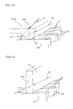
- FIG. 8 shows an example of the positive electrode collector 4A having the convex part 7 at the edge 6.
- the energy beam 8 from the upper surface of the positive electrode collector 4A, it is possible to join the positive electrode collector 4A and joint edges 15 of the positive electrode metallic foil 1A by welding.
- FIG. 10 shows an example of the positive electrode collector 31A having the convex part 33 thicker than that of the positive electrode collector 4A in the FIG. 8.
- FIG. 11 shows an example of a case where a tabular positive electrode collector 41 is placed in such a way that its end face contacts the joint edges 15 of the positive electrode metallic foil 1A.
- the lithium secondary cell of the present invention can also be manufactured by joining the positive electrode collector 41 without the convex part and a plurality of positive electrode metallic foils 1A.
- FIG. 12 shows an example of a case where a convex part 52 is provided on a predetermined part except the edge of a positive electrode collector 51A.
- a convex part 52 is provided on a predetermined part except the edge of a positive electrode collector 51A.
- the joint (negative joint) between the joint edges 15 of the negative electrode metallic foil 1B and the predetermined part of the negative electrode collector 4B be formed by irradiating the energy beam 8 onto the convex part 7 protruding toward the joint edges 15 formed on the predetermined part of the negative electrode collector 4B, thereby melting the convex part 7 of the negative electrode collector 4B and welding the convex part 7 of the negative electrode collector 4B and the joint edges 15 of the negative electrode metallic foil 1.
- the predetermined part of the negative electrode collector 4B be the edge 6 of the negative electrode collector 4B from the standpoint of the ease of checking of the joint surface.
- Examples of the method of joining the negative electrode metallic foil and the negative electrode collector of the lithium secondary cell of the present invention include the following methods. That is, as shown in FIG. 9, it is possible to join the negative electrode metallic foil 1B and the negative electrode collector 4B by placing the negative electrode collector 4B provided on the predetermined part of the convex part 7 protruding toward the edges (joint edges) 15 arranged to be joined to the negative electrode collector 4B of the edges of the negative electrode metallic foil 4B in such a way that the convex part 7 closely contacts the side 13 near at least one of the joint edges 15, irradiating the energy beam 8 onto the convex part 7 of the negative electrode collector 4B, melting the convex part 7, welding the melted convex part 7 of the negative electrode collector 4B to the joint edges 15 of the negative electrode metallic foil 1B.
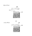
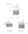
- the methods of closely contacting the side 13 with the convex part 7 by bending the area close to the joint edges 15 include a method as shown in FIG. 17 whereby the area close to the joint edges 15 is bent beforehand using an appropriate method (FIG. 17A), then placing the negative electrode collector 4B on the side 13 (FIG. 17B) or a method as shown in FIG. 18 whereby the negative electrode collector 4B to be joined to the joint edges is pressed with an appropriate pressure, bent and adhered (FIG. 18B and 18C), etc.
- columnar crystals be formed from the negative electrode metallic foil toward the negative electrode collector at the joint between the negative electrode metallic foil and the negative electrode collector.
- a welded metal grows (epitaxial growth) on crystal grains of the base material (unwelded part) in the same crystal orientation.
- the solid phase formed in this way grows toward the inside of the welded bead (welded part) as the heat source moves. This growth tends to continue in the direction with the maximum temperature gradient and the crystal grows almost extending in one such direction and the crystal grown in this way is called "columnar crystal".
- the melted part of the negative electrode collector is recrystallized as it is cooled down and the heat of the melted part spreads rapidly through the negative electrode metallic foil. That is, the temperature of the melted metal corresponding to the part adhered to the negative electrode metallic foil decreases and the columnar crystals are formed more easily from the negative electrode metallic foil toward the negative electrode collector with the interface between the negative electrode metallic foil and melted metal as the core. Furthermore, in the present invention, the side near the joint edges of the negative electrode metallic foil has close contact with the negative electrode collector without any gaps, providing an optimal contact condition, and therefore the columnar crystals are easily formed with the cooling effect through the negative electrode metallic foil.
- the lithium secondary cell of the present invention in which columnar crystals are formed on the joint from the negative electrode metallic foil toward the negative electrode collector is a lithium secondary cell providing an optimal state of joint between the negative electrode metallic foil and the negative electrode collector, that is, excellent mechanical strength and reliability.
- the shape of the convex part provided on the predetermined part of the negative electrode metallic part used in the lithium secondary cell of the present invention is not limited to a particular one.
- FIG. 15 and FIG. 16 show specific examples of the shape of the convex part.
- the shape of the convex part 7 of the negative electrode collector 4B used in the lithium secondary cell of the present invention can be a trapezoidal shape as shown in FIG. 15 or a spire-like shape as shown in FIG. 16.
- the negative electrode collector 4B is formed of the convex part 7 and other flat part 12 and the difference between the thickness (L 2 ) of the convex part 7 and the thickness (L 1 ) of the flat part 12 is preferably 0.1 mm or more, more preferably 0.6 mm or more and most preferably 0.8 mm or more.
- the difference in thickness between the convex part 7 and flat part 12 is less than 0.1 mm, it is impossible to take advantage of the feature in the shape of the convex part 7 and it is not desirable because the contact between the convex part 7 and the negative electrode metallic foil 1B becomes unstable.
- the upper limit of the difference in thickness between the convex part 7 and flat part 12 of the negative electrode collector 4B is not limited to a particular one, but can be set according to the processing accuracy and strength, etc. of the negative electrode collector as appropriate, for example, 3 mm or less.
- the thickness (L 1 ) of the flat part be 0.2 mm or more, more preferably 0.3 mm or more and most preferably 0.4 mm or more.
- the upper limit of the thickness of the flat part is not limited to a particular one, but can be set according to the strength and weight, etc. of the negative electrode collector as appropriate, for example, 2 mm or less because it is the part not directly related to the welded part.
- the thickness (L 2 ) of the convex part of the negative electrode collector 4B be 0.4 mm or more, more preferably 0.5 mm or more and most preferably 0.6 mm or more. This strengthens the joint between the two.
- the upper limit of the thickness of the convex part is not limited to a particular one, but can be set according to the limit of irradiation power of the energy beam, etc. as appropriate.
- the following are preferable examples of the shape of the energy beam irradiation section of the negative electrode collector used for the lithium secondary cell of the present invention.
- FIG. 9 shows an example of the negative electrode collector 4B having the convex part 7 at the edge 6.
- the energy beam 8 from the upper surface of the negative electrode collector 4B, it is possible to join the negative electrode collector 4B and joint edges 15 of the negative electrode metallic foil 1B by welding.
- FIG. 13 shows an example of the negative electrode collector 31B having the convex part 33 thicker than that of the negative electrode collector 4B in FIG. 9. In this case, it is possible to irradiate an energy beam 34 from the upper surface of the negative electrode collector 31B and join the negative electrode collector 31B and the joint edges 15 of the negative electrode metallic foil 1B by welding.
- FIG. 14 shows an example of a case where a convex part 52 is provided on a predetermined part which is not the edge of the negative electrode collector 51B. In this case, it is possible to irradiate an energy beam 53 onto the back of the negative electrode collector 51B provided with the convex part 52 to join the negative electrode collector 51B and the negative electrode metallic foil 1B.
- the metallic foil and collector are made of the same type of metal in the present invention, and therefore it is possible to join the metallic foil and the collector better and increase the mechanical strength of the current lead-out section.
- the thickness of the positive electrode metallic foil made of aluminum or an aluminum alloy be 15 ⁇ m to 25 ⁇ m and the thickness of the negative electrode metallic foil made of copper or a copper alloy be 7 ⁇ m to 15 ⁇ m.
- an aluminum foil having a thickness of 20 ⁇ m and a copper foil having a thickness of 10 ⁇ m are used.
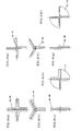
- the positive electrode collector and/or negative electrode collector used in the present invention be of a cross tabular type as shown in FIG. 6A and FIG. 6E, a Y-figured tabular type as shown in FIG. 6B and FIG. 6F or I-figured tabular type as shown in FIG. 6C and FIG. 6G or a circular type with partial notching as shown in FIG. 5, FIG. 6D and FIG. 6H.
- This makes it possible to check the joint easily, reduce the weight or allow the electrolyte to circulate in the whole body during replenishment of the electrolyte, etc.
- the energy beam 8 be irradiated onto the convex part 7 at an angle ⁇ (0° ⁇ 90°) with respect to the normal 3A to the plane including the narrow end face 2 of the positive electrode metallic foil 1A, more preferably irradiated at an angle ⁇ (5° ⁇ 80°) and particularly preferably irradiated at an angle ⁇ (10° ⁇ 60°), and most preferably irradiated at an angle ⁇ (15° ⁇ 45°) (FIG. 8). It is also preferable that the energy beam 8 be focused on or close to or around the surface of the convex part 7 of the positive electrode collector 4A and it is preferable that the energy beam 8 not directly be irradiated onto the positive electrode metallic foil 1A.
- the positive electrode collector 4A be placed in such a way that the convex part 7 crosses the narrow end face 2 at quasi-right angles and the energy beam 8 be irradiated by scanning the line crossing the narrow end face 2 at quasi-right angles using an energy beam generator, that is, by scanning the convex part 7 of the positive electrode collector 4A.
- the energy beam 8 be irradiated onto the convex part 7 at an angle ⁇ (0° ⁇ 90°) with respect to the normal 3A to the plane including the narrow end face 2 of the positive electrode metallic foil 1A, it is preferable that the energy beam 8 be irradiated onto the convex part 7 at quasi-right angles with respect to the line crossing the narrow end face 2 at quasi-right angles.
- this makes it possible to weld the melted body of the positive electrode metallic foil 1A and the positive electrode collector 4A without using brazing filler to join the positive electrode metallic foil 1A and the positive electrode collector 4A. It is also possible to join at least one positive electrode metallic foil 1 with the positive electrode collector 4A by one-time irradiation. Furthermore, since only a predetermined part (convex part 7) of the positive electrode collector 4A can be melted to weld/join the positive electrode metallic foil 1A to the positive electrode collector 4A without causing any damage to the positive electrode metallic foil 1A, it is possible to increase the mechanical strength of the joint.
- joint edges in the present invention refers to a plurality of edges to be joined in one metallic foil or edges to be joined of the respective metallic foils at a plurality of locations and the term “crossing the narrow end face at quasi-right angles” refers to crossing all the narrow end faces of a plurality of joint edges at quasi-right angles.
- the power density of the energy beam at the irradiation point be 3 kW/mm 2 or more, more preferably 4 kW/mm 2 or more and most preferably 5 kW/mm 2 or more. This is because in the case where the energy beam at the irradiation point is less than 3 kW/mm 2 , the joint condition is not good and the mechanical strength may be considered insufficient.
- the upper limit of the power density is not limited to a particular one, but can be determined from the standpoint of prevention of damage to the positive electrode collector or the positive electrode metallic foil connected thereto as appropriate, for example, 60 kW/mm 2 or less.
- power density of energy beam in the present invention refers to a value obtained by dividing the power of the energy beam (kW) by the spot area (mm 2 ) of an irradiation point irradiated with the energy beam in the predetermined part of the positive or negative electrode collector.
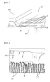
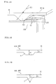
- FIG. 2 is a photographic replica diagram showing an example of a joint body joined using an aluminum foil of 20 ⁇ m for the positive electrode metallic foil 1A, an aluminum material for the part (convex part) of 2 mm long to be melted. by the energy beam in the positive electrode collector 4A and by irradiating a YAG laser.
- FIG. 2 shows that the positive electrode metallic foil 1A is welded in such a way that the entire edge is covered with the joint surface 9 of the positive electrode collector 4A, and therefore it is understood that the positive electrode metallic foil 1A is firmly joined to the positive electrode collector 4A.
- neighboring positive electrode metallic foils 1A are arranged with a gap 10 kept in between, but since the shape of the melted body of the predetermined part of the positive electrode collector 4A is maintained on the edges of the positive electrode metallic foils 1A by its surface tension, even if the gap 10 exists, the gap 10 is not immersed and the melted body and the part contacting the edges of the positive electrode metallic foils 1A are joined.
- the gap 10 is not immersed and the melted body and the part contacting the edges of the positive electrode metallic foils 1A are joined.
- the energy beam 8 be irradiated onto the convex part 7 at an angle ⁇ (0° ⁇ 30°) with respect to the normal 3B to the plane including the side 13 near the joint edges 15 of the negative electrode metallic foil 1B, more preferably irradiated at an angle ⁇ (0° ⁇ 10°) and most preferably irradiated at an angle ⁇ (0° ⁇ 5°) (FIG. 9). Furthermore, it is preferable that the energy beam 8 be focused onto the surface or around the convex part 7 of the negative electrode collector 4B and it is preferable that the energy beam 8 not be directly irradiated onto the negative electrode metallic foil 1B.
- the negative electrode collector 4B be placed in such a way that the convex part 7 crosses the side 13 at quasi-right angles and the energy beam 8 be irradiated by scanning the beam crossing the side 13 at quasi-right angles using an energy beam generator, that is, by scanning the convex part 7 of the negative electrode collector 4B.
- an energy beam generator that is, by scanning the convex part 7 of the negative electrode collector 4B.
- the energy beam 8 be irradiated onto the convex part 7 at quasi-right angles with respect to the line crossing the side 13 at quasi-right angles.
- this makes it possible to weld the melted body of the negative electrode metallic foil 1B and the negative electrode collector 4B without using the brazing filler to join the negative electrode metallic foil 1B and the negative electrode collector 4B. It is also possible to join at least one negative electrode metallic foil 1B to the negative electrode collector 4B by one-time irradiation. Furthermore, since only a predetermined part (convex part 7) of the negative electrode collector 4B can be melted to weld/join the negative electrode metallic foil 1B with the negative electrode collector 4B without causing any damage to the negative electrode metallic foil 1B, it is possible to increase the mechanical strength of the joint.
- crossing the side at quasi-right angles refers to crossing the all the sides near a plurality of joint edges at quasi-right angles.
- the negative electrode joint of the lithium secondary cell of the present invention when the negative electrode joint of the lithium secondary cell of the present invention is formed, it is preferable that the following Expression (7) be satisfied when the thickness of the convex part of the negative electrode collector is L 2 (mm) and the power density of the energy beam at the irradiation point is E (kW/mm 2 ).
- the lithium secondary cell of the present invention suppresses damage to the negative electrode metallic foil and has the special property that the joint has strong mechanical strength.
- the irradiation point of the energy beam of the negative electrode collector have a flat shape. This suppresses diffused reflection of energy beams and provides the special property of suppressing damage to the negative electrode metallic foil.
- the flat shape needs only to apply to at least a range wider than the irradiation point.
- the spot diameter of the irradiation point be 1 mm or less. This suppresses irradiation of energy beams onto unnecessary locations and provides the special property of having an optimal joint condition because damage to the negative electrode metallic foil is suppressed.
- the lithium secondary cell of the present invention is particularly suitable for the case where the neighboring metallic foils are arranged with a certain gap kept in between.
- the energy beam 8 shown in FIG. 8 and FIG. 9 be generated by a laser or electron beam having a high energy density and a low heating value and it is also preferable that the energy beam 8 be continuous wave.
- This allows energy to be irradiated focused on the surface of the convex part 7, making it possible to efficiently melt the convex part 7 and suppress damage to the positive electrode metallic foil 1A or negative electrode metallic foil 1B.
- a YAG laser is particularly preferable because it can be focused better and the energy density at the position of the positive electrode metallic foil 1A or negative electrode metallic foil 1B placed away from the focus is smaller, making it possible to suppress damage to the positive electrode metallic foil 1A or negative electrode metallic foil 1B better.
- the energy beam 8 in FIG. 8 be irradiated using an energy beam generator capable of continuous irradiation and that the energy beam 8 be irradiated using an energy beam generator capable of scanning the plane parallel to the plane including the narrow end face 2.
- the scanning speed of the energy beam to be irradiated be 0.1 to 100 m/min, more preferably 1 to 30 m/min and most preferably 2 to 10 m/min.
- the predetermined part of the positive electrode collector 4A has the convex part 7, it is preferable that the convex part 7 be irradiated with the energy beam 8 by scanning it using the energy beam generator.
- the present invention it is preferable to provide a plurality of positive electrode collectors 4A according to the number of arranged positive electrode metallic foils 1A and arrange the plurality of positive electrode collectors 4A one after another in such a way that their respective convex parts 7 cross the narrow end face 2 at quasi-right angles. This allows the plurality of positive electrode metallic foils 1A to be joined through one-time irradiation.
- the energy beam 8 shown in FIG. 9 be irradiated using an energy beam generator capable of continuous irradiation and that the energy beam 8 be irradiated using the energy beam generator capable of scanning the plane parallel to the plane including the side 13.
- the predetermined part of the negative electrode collector 4B has the convex part 7, it is preferable that the convex part 7 be irradiated with the energy beam 8 by scanning it using the energy beam generator.
- the joint supplement material to support the joint between the positive electrode collector and positive electrode metallic foil be applied to the positive electrode metallic foil and/or predetermined parts of the positive electrode collector or inserted between the positive electrode metallic foil and the predetermined parts of the positive electrode collector, the predetermined part of the positive electrode collector and joint material be irradiated with an energy beam, melted and the melted predetermined part of the positive electrode collector and joint material be welded to the joint edges of the positive metallic foil.
- the joint supplement material to support the joint between the negative electrode collector and negative electrode metallic foil be applied to the negative electrode metallic foil and/or predetermined parts of the negative electrode collector or inserted between the negative electrode metallic foil and the predetermined parts of the negative electrode collector, the predetermined part of the negative electrode collector and joint material be irradiated with an energy beam, melted and the melted predetermined part of the negative electrode collector and joint material be welded to the joint edges of the negative metallic foil.
- the present invention is ideally applicable to a wind type or laminate type inner electrode body, and more particularly, to those having a capacity of 2 Ah or more.
- the use of the cell is not limited to a particular field and is suitable for starting an engine as a large capacity vehicle-mounted battery intended to produce large output by connecting cells in series and requiring space-saving so as to mount multiple cells or for driving a motor of an electric car or hybrid electric car.
- a joint test is conducted using continuous wave YAG laser as an energy beam and by setting various joint conditions such as the shape of the joint (convex part) of the negative electrode collector, the way to make the negative electrode metallic foil contact the negative electrode collector, the output of the YAG laser, scanning speed, etc. and the section of the joint body obtained is observed using a microscope.
- the metal that constitutes the negative electrode metallic foil and negative electrode collector is copper (JIS C1100). The results are shown in FIG. 21 to FIG. 25.
- comparative example 2 shows that no columnar crystals are observed but the negative electrode metallic foil and negative electrode collector are joined partially. However, it has been discovered that its joint area is small and the joint is not in stable condition compared to the Embodiments.
- the present invention can provide a lithium secondary cell with excellent productivity and space-saving capability.
- the invention provides a lithium secondary cell including an inner electrode body impregnated with a non-aqueous electrolyte, made up of a positive electrode and a negative electrode each made of at least one metallic foil wound or laminated together and collectors to lead out a current from this inner electrode body.
- the edges of the metallic foil of the positive electrode and/or the negative electrode and predetermined parts of the positive electrode collector and/or negative electrode collector are joined together to lead out a current from the inner electrode body.
- the edges of the metallic foil, the edges (joint edges) arranged to be joined to the predetermined parts of the positive electrode collector and/or the negative electrode collector and the predetermined parts of the positive electrode collector and/or the negative electrode collector are joined together.
- the lithium secondary cell has excellent productivity and space-saving capability.
Abstract
Description
- The present invention relates to a lithium secondary cell (hereinafter simply referred to as "cell"), and more particularly, to a lithium secondary cell with excellent productivity and space-saving capability.
- The development of lithium secondary cells is underway as motor drive power supplies for electric cars and hybrid electric cars (hereinafter simply referred to as "electric car, etc.") in response to a growing international demand for resource saving and energy saving to protect global environment.
- This lithium secondary cell contains an inner electrode body (hereinafter simply referred to as "electrode body") made up of a positive electrode and a negative electrode wound or laminated together with a separator made of a porous polymer film inserted in between so that the positive electrode and the negative electrode do not directly contact each other.
- As shown in FIG. 20, a conventional wind type inner electrode body 61 is manufactured with a positive electrode 62 and negative electrode 63 wound with a separator 64 inserted in between, each provided with at least one collector tab 65 for the positive electrode and one collector tab 66 for the negative electrode (hereinafter referred to as "collector tabs 65 and 66"). Then, as shown in FIG. 19, the edges on the opposite side of the collector tabs 65 and 66 connected to the electrode plates 62 and 63 are attached to internal terminals 69A and 69B, etc. Reference numeral 76 denotes an elastic body (packing); 77, an insulation polymer film; 78, a pressure reducing valve; 79, a metallic foil.
- Metallic foils, etc. are used for the electrode plates, such as aluminum, etc. for the positive electrode and copper or nickel for the negative electrode as collector substrates, and each electrode plate is formed by applying an electrode active material and the collector tabs are placed on at least one side of these collector substrates.
- However, the collector tabs need to be attached to the electrode plates one by one, for example, by spot-welding, when the electrode body is wound, and the problem is that its process is complicated. Furthermore, at the edges on the opposite side connected to the electrode plates of the collector tabs, the plurality of collector tabs need to be bound and attached to the internal terminals by, for example, riveting, and therefore its process is also complicated and has a problem that it is not easy to connect the collector tabs while maintaining them at low resistance. Furthermore, there is another problem that connecting the electrode body and internal terminals using a plurality of collector tabs requires quite a large space accordingly.
- The present invention has been implemented in view of the above-described conventional problems and it is an object of the present invention to provide a lithium secondary cell with excellent productivity and space-saving capability by adopting a configuration that each electrode plate and collector are directly joined to the current lead-out part from the inner electrode body to lead out a current.
- That is, the present invention provides a lithium secondary cell comprising an inner electrode body impregnated with a non-aqueous electrolyte, made up of a positive electrode and a negative electrode each made of at least one metallic foil wound or laminated together and a positive electrode collector and a negative electrode collector to lead out a current from this inner electrode body, characterized in that the edges of the above-described metallic foils constituting the above-described positive electrode and/or the above-described negative electrode and predetermined parts of the above-described positive electrode collector and negative electrode collector are joined together to lead out a current from the above-described inner electrode body, and of the edges of the above-described metallic foils, the arranged edges (joint edges) to be joined to the above-described predetermined parts of the above-described positive electrode collector and/or the above-described negative electrode collector and the above-described predetermined parts of the above-described positive electrode collector and/or the above-described negative electrode collector are joined together.
- At this time, the present invention can also be constructed in such a way as to further comprise an electrode cover including internal terminals, external terminals and a cell cover, characterized in that the above-described positive electrode collector and/or the above-described negative electrode collector are connected to the above-described internal terminals using electrode leads.
- Furthermore, the above-described collector can also serve as an electrode cover.
- The present invention is preferably constructed in such a way that the joint edges of the metallic foil constituting the positive electrode (positive electrode metallic foil) and a joint having a joint surface at the edge that extends from the predetermined part of the positive electrode collector toward the joint edges are joined with the narrow end face of the joint edges facing the joint surface. The present invention is preferably constructed in such a way that the positive electrode metallic foil and the positive electrode collector are made of aluminum or an aluminum alloy and the predetermined part of the positive electrode collector is the edge of the positive electrode collector.
- Furthermore, the present invention is preferably constructed in such a way that the joint edges of the metallic foil constituting the negative electrode (negative electrode metallic foil) and a joint having a joint surface at the edge that extends from the predetermined part of the negative electrode collector toward the joint edges are joined with the side near the joint edges adhered to the joint surface. The present invention is preferably constructed in such a way that the negative electrode metallic foil and the negative electrode collector are made of copper or a copper alloy and the side and the joint surface are closely contacted by bending the part near the joint edges. The present invention is preferably constructed in such a way that columnar crystals are formed from the metallic foil toward the negative electrode collector at the joint between the metallic foil and the negative electrode collector. The predetermined part of the negative electrode collector is preferably the edge of the negative electrode collector.
- The joint between the joint edges of the positive electrode metallic foil and the predetermined part of the positive electrode collector (positive electrode joint) is preferably formed by irradiating a convex part protruding toward the joint edges formed on the predetermined part of the positive electrode collector with energy beams, melting the convex part of the positive electrode collector and welding the convex part of the positive electrode collector to the joint edges of the positive electrode metallic foil.
- Furthermore, the present invention is preferably constructed in such a way that the joint between the joint edges of the negative electrode metallic foil and the predetermined part of the negative electrode collector (negative electrode joint) is formed by irradiating a convex part protruding toward the joint edge formed on the predetermined part of the negative electrode collector with energy beams, melting the convex part of the negative electrode collector and welding the convex part of the negative electrode collector to the joint edges of the negative electrode metallic foil.
- The shape of the positive electrode collector and/or negative electrode collector is not limited to a particular shape, but it is preferably a cross-, Y- or I-figured tabular collector or a circular collector with partial notching.
- The positive electrode collector and/or negative electrode collector is preferably formed of the convex part and other flat part and the difference between the thickness (L2) of the convex part and the thickness (L1) of the flat part is 0.1 mm or more, the thickness of the flat part of the positive electrode collector is preferably 0.4 mm or more and the thickness of the convex part of the positive electrode collector is preferably 0.6 mm or more.
- The present invention is preferably constructed in such a way that when the positive electrode joint is formed, the energy beam is irradiated onto the predetermined part at an angle (0°<≤90°) with respect to the normal to the plane including the narrow end face of the positive electrode metallic foil and when the positive electrode joint is formed, the power density of the energy beam at the irradiation point is 3 kW/mm2 or more.
- In the present invention, the thickness of the flat part of the negative electrode collector is preferably 0.2 mm or more and the thickness of the convex part of the negative electrode collector is preferably 0.4 mm or more.
- The present invention is preferably constructed in such a way that when the negative electrode joint is formed, the energy beam is irradiated onto the predetermined part at an angle (0°<≤30°) with respect to the normal to the plane including the side of the negative electrode metallic foil and when the negative electrode joint is formed, the power density of the energy beam at the irradiation point is 6 kW/mm2 or more.
- When the negative electrode joint is formed, if the thickness of the convex part is L1 (mm) and the power density is E (kW/mm2), it is preferable that the following Expression (2) be satisfied, that the irradiation point of the energy beam at the negative electrode collector be plane, and that the spot diameter of the irradiation point be 1 mm or less.
-
- The positive electrode collector is preferably placed in such a way that the convex part crosses the narrow end face at quasi-right angles. The energy beam is preferably irradiated onto the convex part of the positive electrode collector at quasi-right angles with respect to the line crossing the narrow end face at quasi-right angles.
- The negative electrode collector is preferably placed in such a way that the convex part crosses the side of the negative electrode metallic foil at quasi-right angles. The energy beam is preferably irradiated onto the convex part of the negative electrode collector at quasi-right angles with respect to the line crossing the side of the negative electrode metallic foil at quasi-right angles.
- The energy beam is preferably not directly irradiated onto the metallic foil. Neighboring metallic foils are preferably placed with a certain gap kept in between. Furthermore, the energy beam is preferably constituted by a laser or electron beam. Furthermore, the energy beam is preferably a continuous wave. The laser is preferably a YAG laser. A joint material for supporting the joint between the positive electrode collector and the positive electrode metallic foil is preferably applied to the predetermined part of the positive electrode metallic foil and/or the positive electrode collector or inserted between the positive electrode metallic foil and the positive electrode collector, and formed by irradiating the predetermined part of the positive electrode collector and the joint material with an energy beam and thereby melting the two and welding the melted predetermined part of the positive electrode collector and the joint material to the joint edges of the positive electrode metallic foil.
- A joint material for supporting the joint between the negative electrode collector and the negative electrode metallic foil is preferably applied to the negative electrode metallic foil and/or the predetermined part of the negative electrode collector or inserted between the negative electrode metallic foil and the predetermined part of the negative electrode collector, and formed by irradiating the predetermined part of the negative electrode collector and the joint material with an energy beam and thereby melting the two and welding the melted predetermined part of the negative electrode collector and the joint material to the joint edges of the negative electrode metallic foil.
- The present invention is preferably applicable to a cell having a capacity of 2 Ah or more and used to start an engine or to drive a motor of an electric car or hybrid electric car.
-
- FIG. 1 is a perspective view schematically showing an example of a joint between a positive electrode metallic foil and positive electrode collector of a lithium secondary cell of the present invention.
- FIG. 2 is a replica diagram showing an example of a current lead-out part where the positive electrode metallic foil and positive electrode collector are joined.
- FIG. 3 is a perspective view schematically showing an example of a joint between a negative electrode metallic foil and negative electrode collector of the lithium secondary cell of the present invention.
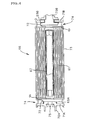
- FIG. 4 is a sectional view showing an embodiment of the lithium secondary cell of the present invention.
- FIG. 5 is a replica diagram of a photo showing an example of a current lead-out part where a wind type electrode body and positive electrode collector of the lithium secondary cell of the present invention are joined.
- FIG. 6 is a schematic view showing examples of the collector used for the lithium secondary cell of the present invention.
- FIG. 7 is a sectional view showing another embodiment of the lithium secondary cell of the present invention.
- FIG. 8 is a perspective view schematically showing an example of an energy beam irradiation section of the positive electrode collector used for the lithium secondary cell of the present invention.
- FIG. 9 is a perspective view schematically showing an example of an energy beam irradiation section of the negative electrode collector used for the lithium secondary cell of the present invention.
- FIG. 10 is a perspective view schematically showing another example of the energy beam irradiation section of the positive electrode collector used for the lithium secondary cell of the present invention.
- FIG. 11 is a perspective view schematically showing a further example of the energy beam irradiation section of the positive electrode collector used for the lithium secondary cell of the present invention.
- FIG. 12 is a perspective view schematically showing a still further example of the energy beam irradiation section of the positive electrode collector used for the lithium secondary cell of the present invention.
- FIG. 13 is a perspective view schematically showing another example of the energy beam irradiation section of the negative electrode collector used for the lithium secondary cell of the present invention.
- FIG. 14 is a perspective view schematically showing a further example of the energy beam irradiation section of the negative electrode collector used for the lithium secondary cell of the present invention.
- FIG. 15 is a schematic view showing an example of the shape of a convex part of the collector used for the lithium secondary cell of the present invention.
- FIG. 16 is a schematic view showing another example of the shape of the convex part of the collector used for the lithium secondary cell of the present invention.
- FIG. 17 is a schematic view showing an example of a method of bending the metallic foil.
- FIG. 18 is a schematic view illustrating another example of the method of bending the metallic foil.
- FIG. 19 is a sectional view showing an embodiment of a conventional lithium secondary cell.
- FIG. 20 is a perspective view showing an example of a wind type inner electrode body.
- FIG. 21 is a microphotograph showing a metal organization of a section of a joint body in Embodiment 1.
- FIG. 22 is a microphotograph showing a metal organization of a section of a joint body in Embodiment 2.
- FIG. 23 is a microphotograph showing a metal organization of a section of a joint body in Embodiment 3.
- FIG. 24 is a microphotograph showing a metal organization of a section of a joint body in comparative example 1.
- FIG. 25 is a microphotograph showing a metal organization of a section of a joint body in comparative example 2.
-
- With reference now to the attached drawings, embodiments of the present invention will be explained below.
- As shown in FIG. 4, the lithium secondary cell of the present invention is a lithium secondary cell 68 comprising an inner electrode body (wind type inner electrode body 61) impregnated with a non-aqueous electrolyte, made up of a positive electrode and a negative electrode each made of at least one metallic foil wound or laminated, a positive electrode collector 4A and negative electrode collector 4B to lead out a current from this inner electrode body, characterized in that the edges of at least one metallic foil constituting the positive electrode and/or the negative electrode and predetermined parts of the positive electrode collector 4A and/or negative electrode collector 4B are joined together to lead out a current from the inner electrode body, and of the edges of the metallic foils, the arranged edges (joint edges) 15 to be joined to the predetermined parts of the positive electrode collector 4A and/or the negative electrode collector 4B and the predetermined parts of the positive electrode collector 4A and/or the negative electrode collector 4B are joined together.
- Furthermore, FIG. 1 is a perspective view schematically showing an example of a joint between a positive electrode and positive electrode collector of the lithium secondary cell of the present invention and shows that the edges of at least one metallic foil (positive electrode metallic foil 1A) making up the positive electrode and a predetermined part of the positive electrode collector 4A are joined to lead out a current from the inner electrode body and further shows that the edges (joint edges) 15 arranged to be joined to the predetermined part of the positive electrode collector 4A of the edges of the metallic foil and the predetermined part of the positive electrode collector 4A are joined.
- Furthermore, FIG. 3 is a perspective view schematically showing an example of a joint between the negative electrode and negative electrode collector of the lithium secondary cell of the present invention and shows that the edges of at least one metallic foil (negative electrode metallic foil 1B) making up the negative electrode and a predetermined part of the negative electrode collector 4B are joined to lead out a current from the inner electrode body and further shows that the edges (joint edges) 15 arranged to be joined to the predetermined part of the negative electrode collector 4B of the edges of the metallic foil and the predetermined part of the negative electrode collector 4B are joined.
- As shown in FIG. 4, in addition to the above-described configuration, the present invention can also have a configuration comprising an electrode cover provided with internal terminals 69A and 69B, external terminals 70A and 70B and cell covers 71A and 71B, with the positive electrode collector 4A and negative electrode collector 4B connected to the internal terminals 69A and 69B using their respective electrode leads 72. At this time, the electrode leads 72 are preferably made of a metal of the same type including its alloy as that of the collectors 4A and 4B connected and the internal terminals 69A and 69B. More specifically, if aluminum or an aluminum alloy is used for the positive electrode internal terminal 69A and positive electrode collector 4A, it is preferable that aluminum or an aluminum alloy be used for the positive electrode leads, and if copper or a copper alloy is used for the negative electrode internal terminal 69B and negative electrode collector 4B, it is preferable that copper or a copper alloy be used for the negative electrode leads.
- The present invention can also be implemented by directly joining the collectors 4A and 4B with the internal terminals 69A and 69B to carry a current instead of using the electrode leads.
- Furthermore, the present invention can also be implemented by using the current lead-out part of the present invention for the positive electrode and negative electrode or either of the two.
- Furthermore, in the present invention, the collector 54 can also serve as the electrode cover as shown in FIG. 7. FIG. 7 shows an example of a case of a cylindrical cell case 73 with one end left open and constriction processing applied to the other end. However, as far as the collector 54 also serves as the electrode cover, the shape of the cell is not limited to a particular one and both ends of the cell case 73 can either be subjected to constriction processing or left open. Furthermore, FIG. 7 shows an example of a case where a pressure reducing hole 75 is provided on the positive electrode side, but a pressure reducing hole 75 may also be provided on the negative electrode side.
- As shown in FIG. 4 and FIG. 7, adopting a configuration that the electrode plates and the collectors 4A, 4B and 54 directly joined to the current lead-out part from the inner electrode body (wind type inner electrode body 61) to lead out a current eliminates the need to use the collector tabs which are the conventional current lead-out means and thereby eliminates the need for a complicated process for attaching collector tabs, thus improving productivity and at the same time saves the space corresponding to the length of the collector tab, thus improving the space-saving capability. The current lead-out part of the present invention is manufactured as described later, and therefore it is easier than attaching a plurality of collector tabs and more advantageous than the collector tabs in terms of space-saving. This will be described in further detail below.
- As shown in FIG. 1, it is preferable that the present invention be constructed in such a way that the joint edges 15 of the positive electrode metallic foil 1A making up the positive electrode is joined to the joint 5 having a joint surface at the end, which extends from a predetermined part of the positive electrode collector 4A toward the joint edges 15, with the narrow end face 2 facing the joint surface. Aluminum or an aluminum alloy is preferably used as the metal material making up the positive electrode metallic foil 1A and the positive electrode collector 4A to be joined thereto from the standpoint that it displays an optimal characteristic as the component of the lithium secondary cell.
- Furthermore, as shown in FIG. 8, the joint (positive electrode joint) between the joint edges 15 of the positive electrode metallic foil 1A and the predetermined part of the positive electrode collector 4A is preferably formed by irradiating a convex part 7 protruding toward the joint edges 15 formed on the predetermined part of the positive electrode collector 4A with an energy beam 8, melting the convex part 7 of the positive electrode collector 4A and thereby welding the convex part 7 of the positive electrode collector 4A to the joint edges 15 of the positive electrode metallic foil 1A. Furthermore, it is preferable that the predetermined part of the positive electrode collector 4A be an edge 6 of the positive electrode collector 4A because this makes it easier to check the joint surface.
- The following is an example of a method of forming the positive electrode joint of the lithium secondary cell of the present invention. That is, as shown in FIG. 8, this method consists of forming a joint body between the positive electrode metallic foil 1A and the positive electrode collector 4A by placing the positive electrode collector 4A having the convex part 7 protruding toward the predetermined part of the edges (joint edges) 15 arranged to be joined to the positive electrode collector 4A of the edges of the positive electrode metallic foil 1A in such a way that the convex part 7 has contact with or comes close to at least one of the narrow end faces 2, irradiating the convex part 7 of the positive electrode collector 4A with the energy beam 8 and melting the convex part 7 and welding the melted convex part 7 of the positive electrode collector 4A to the joint edges 15 of the positive electrode metallic foil 1A.
- Furthermore, the shape of the convex part 7 protruding toward the joint edges 15 of the positive electrode metallic foil 1A on the predetermined part of the positive electrode collector 4A is not limited to a particular one, but it is preferable that the shape of the convex part 7 secure the contact between the convex surface of the convex part 7 and the narrow end face 2 of the positive electrode metallic foil 1A so as to facilitate the welding of the joint edge 15 of the positive electrode metallic foil 1A and the positive electrode collector 4A and a preferable example can include a case where the convex surface of the convex part 7 and the narrow end face 2 of the positive electrode metallic foil 1A are formed in such a way as to have point contact with each other.
- FIG. 15 and FIG. 16 show specific examples of the shape of the convex part of the collector. The shape of the convex part 7 of the positive electrode collector 4A and the negative electrode collector 4B (described later) can be either a trapezoidal shape as shown in FIG. 15 or a spire-like shape as shown in FIG. 16.
- In FIG. 15 and FIG. 16, L1 denotes the thickness of the flat part 12 and L2 denotes the thickness of the convex part 7.
- In the lithium secondary cell of the present invention, as shown in FIG. 15 and FIG. 16, it is preferable that the positive electrode collector 4A be constructed of the convex part 7 and other flat part 12, the difference between the thickness (L2) of the convex part 7 and the thickness (L1) of the flat part 12 be 0.1 mm or more, more preferably 0.6 mm or more and most preferably 0.8 mm or more. In the case where the difference in thickness between the convex part 7 and flat part 12 is less than 0.1 mm, it is impossible to take advantage of the feature in the shape of the convex part 7 and not desirable because the contact between the convex part 7 and the positive electrode metallic foil 1A becomes unstable. The upper limit of the difference in thickness between the convex part 7 and flat part 12 in the present invention is not limited to a particular one, but can be set according to the processing accuracy and strength, etc. of the positive electrode collector as appropriate, for example, 3 mm or less.
- When the positive electrode collector is pressed against the positive electrode metallic foil to join the two together, it is preferable from the standpoint of preventing deformation or damage, etc. of the positive electrode collector that the thickness (L1) of the flat part of the positive electrode collector 4A be 0.4 mm or more, more preferably 0.5 mm or more and most preferably 0.6 mm or more. The upper limit of the thickness of the flat part is not limited to a particular one, but can be set according to the strength and weight, etc. of the positive electrode collector as appropriate, for example, 2 mm or less because it is the part not directly related to the welded part.
- Furthermore, it is preferable that the thickness (L2) of the convex part of the positive electrode collector 4A be 0.6 mm or more, more preferably 0.7 mm or more and most preferably 0.8 mm or more. This strengthens the joint between the two. The upper limit of the thickness of the convex part is not limited to a particular one, but can be set according to the limit of irradiation power of the energy beam, etc. as appropriate.
- The following shapes can be included in preferable examples of the shape of the energy beam irradiation section of the positive electrode collector used for the lithium secondary cell of the present invention.
- FIG. 8 shows an example of the positive electrode collector 4A having the convex part 7 at the edge 6. In this case, by irradiating the energy beam 8 from the upper surface of the positive electrode collector 4A, it is possible to join the positive electrode collector 4A and joint edges 15 of the positive electrode metallic foil 1A by welding.
- FIG. 10 shows an example of the positive electrode collector 31A having the convex part 33 thicker than that of the positive electrode collector 4A in the FIG. 8. In this case, in addition to irradiating the energy beam 34 from the upper surface of the positive electrode collector 31A, it is also possible to irradiate an energy beam 35 onto the side of the convex part 33 to join the positive electrode collector 31A and the joint edges 15 of the positive electrode metallic foil 1A by welding.
- FIG. 11 shows an example of a case where a tabular positive electrode collector 41 is placed in such a way that its end face contacts the joint edges 15 of the positive electrode metallic foil 1A. In this case, it is also possible to irradiate an energy beam 42 from the side of the positive electrode collector 41 to join the positive electrode collector 41 and the joint edges 15 of the positive electrode metallic foil 1A by welding. Thus, as shown in FIG. 11, the lithium secondary cell of the present invention can also be manufactured by joining the positive electrode collector 41 without the convex part and a plurality of positive electrode metallic foils 1A.
- FIG. 12 shows an example of a case where a convex part 52 is provided on a predetermined part except the edge of a positive electrode collector 51A. In this case, it is possible to irradiate an energy beam 53 onto the back of the positive electrode collector 51A with a convex part 52 to join the positive electrode collector 51A and the positive electrode metallic foil 1A.
- On the other hand, as shown in FIG. 3, in the present invention, it is preferable to join the joint edges 15 of the negative electrode metallic foil 1B that constitutes the negative electrode and the joint 5 having the joint surface at its end which extends from the predetermined part of the negative electrode collector 4B toward the joint edges 15 by closely contacting the side 13 near the joint edges 15 with the joint surface, and it is preferable to use copper or a copper alloy as the metal material constituting the negative electrode metallic foil 1B and the negative electrode collector 4B to be joined thereto from the standpoint of making it display an optimal characteristic as the component of the lithium secondary cell. Furthermore, as shown in FIG. 9, it is also preferable that the joint (negative joint) between the joint edges 15 of the negative electrode metallic foil 1B and the predetermined part of the negative electrode collector 4B be formed by irradiating the energy beam 8 onto the convex part 7 protruding toward the joint edges 15 formed on the predetermined part of the negative electrode collector 4B, thereby melting the convex part 7 of the negative electrode collector 4B and welding the convex part 7 of the negative electrode collector 4B and the joint edges 15 of the negative electrode metallic foil 1. Furthermore, it is also preferable that the predetermined part of the negative electrode collector 4B be the edge 6 of the negative electrode collector 4B from the standpoint of the ease of checking of the joint surface.
- Examples of the method of joining the negative electrode metallic foil and the negative electrode collector of the lithium secondary cell of the present invention include the following methods. That is, as shown in FIG. 9, it is possible to join the negative electrode metallic foil 1B and the negative electrode collector 4B by placing the negative electrode collector 4B provided on the predetermined part of the convex part 7 protruding toward the edges (joint edges) 15 arranged to be joined to the negative electrode collector 4B of the edges of the negative electrode metallic foil 4B in such a way that the convex part 7 closely contacts the side 13 near at least one of the joint edges 15, irradiating the energy beam 8 onto the convex part 7 of the negative electrode collector 4B, melting the convex part 7, welding the melted convex part 7 of the negative electrode collector 4B to the joint edges 15 of the negative electrode metallic foil 1B.
- At this time, it is possible to adhere the side 13 to the convex part 7 which is the joint surface by bending the area close to the joint edges 15. The methods of closely contacting the side 13 with the convex part 7 by bending the area close to the joint edges 15 include a method as shown in FIG. 17 whereby the area close to the joint edges 15 is bent beforehand using an appropriate method (FIG. 17A), then placing the negative electrode collector 4B on the side 13 (FIG. 17B) or a method as shown in FIG. 18 whereby the negative electrode collector 4B to be joined to the joint edges is pressed with an appropriate pressure, bent and adhered (FIG. 18B and 18C), etc.
- In the lithium secondary cell of the present invention, it is preferable that columnar crystals be formed from the negative electrode metallic foil toward the negative electrode collector at the joint between the negative electrode metallic foil and the negative electrode collector. Generally, a welded metal grows (epitaxial growth) on crystal grains of the base material (unwelded part) in the same crystal orientation. The solid phase formed in this way grows toward the inside of the welded bead (welded part) as the heat source moves. This growth tends to continue in the direction with the maximum temperature gradient and the crystal grows almost extending in one such direction and the crystal grown in this way is called "columnar crystal".
- The melted part of the negative electrode collector is recrystallized as it is cooled down and the heat of the melted part spreads rapidly through the negative electrode metallic foil. That is, the temperature of the melted metal corresponding to the part adhered to the negative electrode metallic foil decreases and the columnar crystals are formed more easily from the negative electrode metallic foil toward the negative electrode collector with the interface between the negative electrode metallic foil and melted metal as the core. Furthermore, in the present invention, the side near the joint edges of the negative electrode metallic foil has close contact with the negative electrode collector without any gaps, providing an optimal contact condition, and therefore the columnar crystals are easily formed with the cooling effect through the negative electrode metallic foil. The lithium secondary cell of the present invention in which columnar crystals are formed on the joint from the negative electrode metallic foil toward the negative electrode collector is a lithium secondary cell providing an optimal state of joint between the negative electrode metallic foil and the negative electrode collector, that is, excellent mechanical strength and reliability.
- The shape of the convex part provided on the predetermined part of the negative electrode metallic part used in the lithium secondary cell of the present invention is not limited to a particular one.
- Here, FIG. 15 and FIG. 16 show specific examples of the shape of the convex part. The shape of the convex part 7 of the negative electrode collector 4B used in the lithium secondary cell of the present invention can be a trapezoidal shape as shown in FIG. 15 or a spire-like shape as shown in FIG. 16.
- In the lithium secondary cell of the present invention, as shown in FIG. 15 and FIG. 16, the negative electrode collector 4B is formed of the convex part 7 and other flat part 12 and the difference between the thickness (L2) of the convex part 7 and the thickness (L1) of the flat part 12 is preferably 0.1 mm or more, more preferably 0.6 mm or more and most preferably 0.8 mm or more. In the case where the difference in thickness between the convex part 7 and flat part 12 is less than 0.1 mm, it is impossible to take advantage of the feature in the shape of the convex part 7 and it is not desirable because the contact between the convex part 7 and the negative electrode metallic foil 1B becomes unstable. Furthermore, the upper limit of the difference in thickness between the convex part 7 and flat part 12 of the negative electrode collector 4B is not limited to a particular one, but can be set according to the processing accuracy and strength, etc. of the negative electrode collector as appropriate, for example, 3 mm or less.
- When the negative electrode collector is pressed against the negative electrode metallic foil to join the two, it is preferable from the standpoint of preventing deformation or damage, etc. of the negative electrode collector that the thickness (L1) of the flat part be 0.2 mm or more, more preferably 0.3 mm or more and most preferably 0.4 mm or more. The upper limit of the thickness of the flat part is not limited to a particular one, but can be set according to the strength and weight, etc. of the negative electrode collector as appropriate, for example, 2 mm or less because it is the part not directly related to the welded part.
- Furthermore, it is preferable that the thickness (L2) of the convex part of the negative electrode collector 4B be 0.4 mm or more, more preferably 0.5 mm or more and most preferably 0.6 mm or more. This strengthens the joint between the two. The upper limit of the thickness of the convex part is not limited to a particular one, but can be set according to the limit of irradiation power of the energy beam, etc. as appropriate.
- The following are preferable examples of the shape of the energy beam irradiation section of the negative electrode collector used for the lithium secondary cell of the present invention.
- FIG. 9 shows an example of the negative electrode collector 4B having the convex part 7 at the edge 6. In this case, by irradiating the energy beam 8 from the upper surface of the negative electrode collector 4B, it is possible to join the negative electrode collector 4B and joint edges 15 of the negative electrode metallic foil 1B by welding.
- FIG. 13 shows an example of the negative electrode collector 31B having the convex part 33 thicker than that of the negative electrode collector 4B in FIG. 9. In this case, it is possible to irradiate an energy beam 34 from the upper surface of the negative electrode collector 31B and join the negative electrode collector 31B and the joint edges 15 of the negative electrode metallic foil 1B by welding.
- FIG. 14 shows an example of a case where a convex part 52 is provided on a predetermined part which is not the edge of the negative electrode collector 51B. In this case, it is possible to irradiate an energy beam 53 onto the back of the negative electrode collector 51B provided with the convex part 52 to join the negative electrode collector 51B and the negative electrode metallic foil 1B.
- When aluminum or an aluminum alloy is used for the positive electrode collector and positive electrode metallic foil and copper or a copper alloy is used for the negative electrode collector and negative electrode metallic foil, the metallic foil and collector are made of the same type of metal in the present invention, and therefore it is possible to join the metallic foil and the collector better and increase the mechanical strength of the current lead-out section. In this case, it is preferable that the thickness of the positive electrode metallic foil made of aluminum or an aluminum alloy be 15 µm to 25 µm and the thickness of the negative electrode metallic foil made of copper or a copper alloy be 7 µm to 15 µm. In the case of the cells shown in FIG. 4 and FIG. 7, an aluminum foil having a thickness of 20 µm and a copper foil having a thickness of 10 µm are used.
- It is preferable that the positive electrode collector and/or negative electrode collector used in the present invention be of a cross tabular type as shown in FIG. 6A and FIG. 6E, a Y-figured tabular type as shown in FIG. 6B and FIG. 6F or I-figured tabular type as shown in FIG. 6C and FIG. 6G or a circular type with partial notching as shown in FIG. 5, FIG. 6D and FIG. 6H. This makes it possible to check the joint easily, reduce the weight or allow the electrolyte to circulate in the whole body during replenishment of the electrolyte, etc.
- When the positive electrode joint of the lithium secondary cell of the present invention is formed, it is preferable that the energy beam 8 be irradiated onto the convex part 7 at an angle (0°<≤90°) with respect to the normal 3A to the plane including the narrow end face 2 of the positive electrode metallic foil 1A, more preferably irradiated at an angle (5°≤≤80°) and particularly preferably irradiated at an angle (10°≤≤60°), and most preferably irradiated at an angle (15°≤≤45°) (FIG. 8). It is also preferable that the energy beam 8 be focused on or close to or around the surface of the convex part 7 of the positive electrode collector 4A and it is preferable that the energy beam 8 not directly be irradiated onto the positive electrode metallic foil 1A.
- Furthermore, it is preferable that the positive electrode collector 4A be placed in such a way that the convex part 7 crosses the narrow end face 2 at quasi-right angles and the energy beam 8 be irradiated by scanning the line crossing the narrow end face 2 at quasi-right angles using an energy beam generator, that is, by scanning the convex part 7 of the positive electrode collector 4A. At this time, in addition to the above-described energy beam 8 being irradiated onto the convex part 7 at an angle (0°<≤90°) with respect to the normal 3A to the plane including the narrow end face 2 of the positive electrode metallic foil 1A, it is preferable that the energy beam 8 be irradiated onto the convex part 7 at quasi-right angles with respect to the line crossing the narrow end face 2 at quasi-right angles.
- As shown in FIG. 1, this makes it possible to weld the melted body of the positive electrode metallic foil 1A and the positive electrode collector 4A without using brazing filler to join the positive electrode metallic foil 1A and the positive electrode collector 4A. It is also possible to join at least one positive electrode metallic foil 1 with the positive electrode collector 4A by one-time irradiation. Furthermore, since only a predetermined part (convex part 7) of the positive electrode collector 4A can be melted to weld/join the positive electrode metallic foil 1A to the positive electrode collector 4A without causing any damage to the positive electrode metallic foil 1A, it is possible to increase the mechanical strength of the joint.
- By the way, the term "joint edges" in the present invention refers to a plurality of edges to be joined in one metallic foil or edges to be joined of the respective metallic foils at a plurality of locations and the term "crossing the narrow end face at quasi-right angles" refers to crossing all the narrow end faces of a plurality of joint edges at quasi-right angles.
- When the positive electrode joint of the lithium secondary cell of the present invention is formed, it is preferable that the power density of the energy beam at the irradiation point be 3 kW/mm2 or more, more preferably 4 kW/mm2 or more and most preferably 5 kW/mm2 or more. This is because in the case where the energy beam at the irradiation point is less than 3 kW/mm2, the joint condition is not good and the mechanical strength may be considered insufficient. The upper limit of the power density is not limited to a particular one, but can be determined from the standpoint of prevention of damage to the positive electrode collector or the positive electrode metallic foil connected thereto as appropriate, for example, 60 kW/mm2 or less. The term "power density" of energy beam in the present invention refers to a value obtained by dividing the power of the energy beam (kW) by the spot area (mm2) of an irradiation point irradiated with the energy beam in the predetermined part of the positive or negative electrode collector.
- FIG. 2 is a photographic replica diagram showing an example of a joint body joined using an aluminum foil of 20 µm for the positive electrode metallic foil 1A, an aluminum material for the part (convex part) of 2 mm long to be melted. by the energy beam in the positive electrode collector 4A and by irradiating a YAG laser.
- The example in FIG. 2 shows that the positive electrode metallic foil 1A is welded in such a way that the entire edge is covered with the joint surface 9 of the positive electrode collector 4A, and therefore it is understood that the positive electrode metallic foil 1A is firmly joined to the positive electrode collector 4A.
- In this example, neighboring positive electrode metallic foils 1A are arranged with a gap 10 kept in between, but since the shape of the melted body of the predetermined part of the positive electrode collector 4A is maintained on the edges of the positive electrode metallic foils 1A by its surface tension, even if the gap 10 exists, the gap 10 is not immersed and the melted body and the part contacting the edges of the positive electrode metallic foils 1A are joined. By the way, even if some of the plurality of positive electrode metallic foils 1A are arranged contacting one another or all of them are arranged so as to closely contact one another, it is possible to join these foils.
- When the negative electrode joint of the lithium secondary cell of the present invention is formed, it is preferable that the energy beam 8 be irradiated onto the convex part 7 at an angle (0°≤≤30°) with respect to the normal 3B to the plane including the side 13 near the joint edges 15 of the negative electrode metallic foil 1B, more preferably irradiated at an angle (0°≤≤10°) and most preferably irradiated at an angle (0°≤≤5°) (FIG. 9). Furthermore, it is preferable that the energy beam 8 be focused onto the surface or around the convex part 7 of the negative electrode collector 4B and it is preferable that the energy beam 8 not be directly irradiated onto the negative electrode metallic foil 1B.
- Furthermore, it is preferable that the negative electrode collector 4B be placed in such a way that the convex part 7 crosses the side 13 at quasi-right angles and the energy beam 8 be irradiated by scanning the beam crossing the side 13 at quasi-right angles using an energy beam generator, that is, by scanning the convex part 7 of the negative electrode collector 4B. At this time, in addition to the energy beam 8 being irradiated onto the convex part 7 at an angle (0°≤≤30°) with respect to the normal 3B to the plane including the side 13 of the negative electrode metallic foil 1B, it is preferable that the energy beam 8 be irradiated onto the convex part 7 at quasi-right angles with respect to the line crossing the side 13 at quasi-right angles.
- As shown in FIG. 3, this makes it possible to weld the melted body of the negative electrode metallic foil 1B and the negative electrode collector 4B without using the brazing filler to join the negative electrode metallic foil 1B and the negative electrode collector 4B. It is also possible to join at least one negative electrode metallic foil 1B to the negative electrode collector 4B by one-time irradiation. Furthermore, since only a predetermined part (convex part 7) of the negative electrode collector 4B can be melted to weld/join the negative electrode metallic foil 1B with the negative electrode collector 4B without causing any damage to the negative electrode metallic foil 1B, it is possible to increase the mechanical strength of the joint.
- By the way, the term "crossing the side at quasi-right angles" refers to crossing the all the sides near a plurality of joint edges at quasi-right angles.
- Furthermore, when the negative electrode joint of the lithium secondary cell of the present invention is formed, it is preferable that the following Expression (7) be satisfied when the thickness of the convex part of the negative electrode collector is L2 (mm) and the power density of the energy beam at the irradiation point is E (kW/mm2). By irradiating the energy beam under conditions that satisfy the following Expression (3), the lithium secondary cell of the present invention suppresses damage to the negative electrode metallic foil and has the special property that the joint has strong mechanical strength.
-
- From the standpoint of suppressing damage to the negative electrode metallic foil and having the special property that the joint has strong mechanical strength, it is preferable that the following Expressions (4) and (5) be satisfied.
-
-
- With the lithium secondary cell of the present invention, it is preferable that the irradiation point of the energy beam of the negative electrode collector have a flat shape. This suppresses diffused reflection of energy beams and provides the special property of suppressing damage to the negative electrode metallic foil. By the way, from the standpoint of suppressing diffused reflection of energy beams, the flat shape needs only to apply to at least a range wider than the irradiation point.
- Furthermore, with the lithium secondary cell of the present invention, it is preferable that the spot diameter of the irradiation point be 1 mm or less. This suppresses irradiation of energy beams onto unnecessary locations and provides the special property of having an optimal joint condition because damage to the negative electrode metallic foil is suppressed. The lithium secondary cell of the present invention is particularly suitable for the case where the neighboring metallic foils are arranged with a certain gap kept in between.
- Furthermore, with the present invention, it is preferable that the energy beam 8 shown in FIG. 8 and FIG. 9 be generated by a laser or electron beam having a high energy density and a low heating value and it is also preferable that the energy beam 8 be continuous wave. This allows energy to be irradiated focused on the surface of the convex part 7, making it possible to efficiently melt the convex part 7 and suppress damage to the positive electrode metallic foil 1A or negative electrode metallic foil 1B. Of lasers, a YAG laser is particularly preferable because it can be focused better and the energy density at the position of the positive electrode metallic foil 1A or negative electrode metallic foil 1B placed away from the focus is smaller, making it possible to suppress damage to the positive electrode metallic foil 1A or negative electrode metallic foil 1B better.
- Furthermore, when the positive electrode joint of the lithium secondary cell of the present invention is formed, it is preferable that the energy beam 8 in FIG. 8 be irradiated using an energy beam generator capable of continuous irradiation and that the energy beam 8 be irradiated using an energy beam generator capable of scanning the plane parallel to the plane including the narrow end face 2. Furthermore, it is preferable that the scanning speed of the energy beam to be irradiated be 0.1 to 100 m/min, more preferably 1 to 30 m/min and most preferably 2 to 10 m/min. Furthermore, when the predetermined part of the positive electrode collector 4Ahas the convex part 7, it is preferable that the convex part 7 be irradiated with the energy beam 8 by scanning it using the energy beam generator. Furthermore, with the present invention, it is preferable to provide a plurality of positive electrode collectors 4A according to the number of arranged positive electrode metallic foils 1A and arrange the plurality of positive electrode collectors 4A one after another in such a way that their respective convex parts 7 cross the narrow end face 2 at quasi-right angles. This allows the plurality of positive electrode metallic foils 1A to be joined through one-time irradiation.
- On the other hand, when the negative electrode joint of the lithium secondary cell of the present invention is formed, it is preferable that the energy beam 8 shown in FIG. 9 be irradiated using an energy beam generator capable of continuous irradiation and that the energy beam 8 be irradiated using the energy beam generator capable of scanning the plane parallel to the plane including the side 13. Furthermore, when the predetermined part of the negative electrode collector 4B has the convex part 7, it is preferable that the convex part 7 be irradiated with the energy beam 8 by scanning it using the energy beam generator. Furthermore, with the present invention, it is preferable to provide a plurality of negative electrode collectors 4B according to the number of arranged negative electrode metallic foils 1B and arrange the plurality of negative electrode collectors 4B one after another in such a way that their respective convex parts 7 cross the side 13 at quasi-right angles. This allows the plurality of negative electrode metallic foils 1B to be joined through one-time irradiation.
- When the positive electrode joint of the lithium secondary cell of the present invention is formed, no joint support material such as brazing filler metal is needed, but of course such a material can be used. In such a case, it is preferable that the joint supplement material to support the joint between the positive electrode collector and positive electrode metallic foil be applied to the positive electrode metallic foil and/or predetermined parts of the positive electrode collector or inserted between the positive electrode metallic foil and the predetermined parts of the positive electrode collector, the predetermined part of the positive electrode collector and joint material be irradiated with an energy beam, melted and the melted predetermined part of the positive electrode collector and joint material be welded to the joint edges of the positive metallic foil.
- Furthermore, when the negative electrode joint of the lithium secondary cell of the present invention is formed, no joint support material such as brazing filler metal is needed, but of course such a material can be used. In such a case, it is preferable that the joint supplement material to support the joint between the negative electrode collector and negative electrode metallic foil be applied to the negative electrode metallic foil and/or predetermined parts of the negative electrode collector or inserted between the negative electrode metallic foil and the predetermined parts of the negative electrode collector, the predetermined part of the negative electrode collector and joint material be irradiated with an energy beam, melted and the melted predetermined part of the negative electrode collector and joint material be welded to the joint edges of the negative metallic foil.
- More specifically, the present invention is ideally applicable to a wind type or laminate type inner electrode body, and more particularly, to those having a capacity of 2 Ah or more. The use of the cell is not limited to a particular field and is suitable for starting an engine as a large capacity vehicle-mounted battery intended to produce large output by connecting cells in series and requiring space-saving so as to mount multiple cells or for driving a motor of an electric car or hybrid electric car.
- Embodiments of the present invention will be explained more specifically below, but the present invention is not limited to these embodiments.
- A joint test is conducted using continuous wave YAG laser as an energy beam and by setting various joint conditions such as the shape of the joint (convex part) of the negative electrode collector, the way to make the negative electrode metallic foil contact the negative electrode collector, the output of the YAG laser, scanning speed, etc. and the section of the joint body obtained is observed using a microscope. By the way, the metal that constitutes the negative electrode metallic foil and negative electrode collector is copper (JIS C1100). The results are shown in FIG. 21 to FIG. 25.
- When the negative electrode collector and negative electrode metallic foil are joined in good condition, it is possible to observe columnar crystals formed from the negative electrode metallic foil toward the negative electrode collector (Embodiments 1 to 3).
- On the other hand, it is not possible to observe any columnar crystals at locations where the negative electrode collector and negative electrode metallic foil are not joined as shown in comparative example 1, and equiaxed crystals can be observed instead.
- On the hand, comparative example 2 shows that no columnar crystals are observed but the negative electrode metallic foil and negative electrode collector are joined partially. However, it has been discovered that its joint area is small and the joint is not in stable condition compared to the Embodiments.
- As shown above, it has been confirmed that good joint condition can be obtained under conditions under which columnar crystals are formed from the negative electrode metallic foil toward the negative electrode collector at the joint between the negative electrode metallic foil and the negative electrode collector.
- As described above by adopting a configuration that electrode plates and collectors are directly joined to lead out a current for the part that leads out a current from the inner electrode body, the present invention can provide a lithium secondary cell with excellent productivity and space-saving capability.
- The invention provides a lithium secondary cell including an inner electrode body impregnated with a non-aqueous electrolyte, made up of a positive electrode and a negative electrode each made of at least one metallic foil wound or laminated together and collectors to lead out a current from this inner electrode body. The edges of the metallic foil of the positive electrode and/or the negative electrode and predetermined parts of the positive electrode collector and/or negative electrode collector are joined together to lead out a current from the inner electrode body. The edges of the metallic foil, the edges (joint edges) arranged to be joined to the predetermined parts of the positive electrode collector and/or the negative electrode collector and the predetermined parts of the positive electrode collector and/or the negative electrode collector are joined together. The lithium secondary cell has excellent productivity and space-saving capability.
Claims (41)
- A lithium secondary cell comprising:an inner electrode body impregnated with a non-aqueous electrolyte, made up of a positive electrode and a negative electrode each made of at least one metallic foil wound or laminated together; anda positive electrode collector and a negative electrode collector to lead out a current from the inner electrode body,wherein the edges of said metallic foils of said positive electrode and/or said negative electrode and predetermined parts of said positive electrode collector and/or said negative electrode collector are joined together to lead out a current from said inner electrode body, andof the edges of said metallic foils, the arranged edges (joint edges) to be joined to said predetermined parts of said positive electrode collector and/or said negative electrode collector and said predetermined parts of said positive electrode collector and/or said negative electrode collector are joined together.
- The lithium secondary cell according to claim 1, further comprising an electrode cover including internal terminals, external terminals and a cell cover, wherein said positive electrode collector and/or said negative electrode collector are connected to said internal terminals using electrode leads.
- The lithium secondary cell according to claim 1, wherein said positive electrode collector and/or said negative electrode collector also serve as an electrode cover.
- The lithium secondary cell according to any one of claims 1 to 3, wherein said joint edges of said metallic foil constituting said positive electrode (positive electrode metallic foil) and a joint having a joint surface at the edge that extends from said predetermined part of said positive electrode collector to said joint edges are joined with the narrow end face of said joint edges facing said joint surface.
- The lithium secondary cell according to claim 4, wherein said positive electrode metallic foil and said positive electrode collector are made of aluminum or an aluminum alloy.
- The lithium secondary cell according to any one of claims 1 to 5, wherein said predetermined part of said positive electrode collector is the edge of said positive electrode collector.
- The lithium secondary cell according to any one of claims 1 to 6, wherein said joint edges of said metallic foil constituting said negative electrode (negative electrode metallic foil) and a joint having a joint surface at the edge that extends from said predetermined part of said negative electrode collector to said joint edges are joined with the side near said joint edges adhered to said joint surface.
- The lithium secondary cell according to claim 7, wherein said negative electrode metallic foil and said negative electrode collector are made of copper or a copper alloy.
- The lithium secondary cell according to claim 7 or 8, wherein said side is adhered to said joint surface by bending the part near said joint edges.
- The lithium secondary cell according to any one of claims 7 to 9, wherein columnar crystals are formed from said metallic foil toward said negative electrode collector at the joint between said negative electrode metallic foil and said negative electrode collector.
- The lithium secondary cell according to any one of claims 1 to 10, wherein said predetermined part of said negative electrode collector is the edge of said negative electrode collector.
- The lithium secondary cell according to any one of claims 4 to 11, wherein the joint between said joint edges of said positive electrode metallic foil and said predetermined part of said positive electrode collector (positive electrode joint) is formed by irradiating a convex part protruding toward said joint edges formed on said predetermined part of said positive electrode collector with energy beams, melting said convex part of said positive electrode collector and welding said convex part of said positive electrode collector with said joint edges of said positive electrode metallic foil.
- The lithium secondary cell according to any one of claims 7 to 12, wherein the joint between said joint edges of said negative electrode metallic foil and said predetermined part of said negative electrode collector (negative electrode joint) is formed by irradiating a convex part protruding toward said joint edges formed on said predetermined part of said negative electrode collector with energy beams, melting said convex part of said negative electrode collector and welding said convex part of said negative electrode collector with said joint edges of said negative electrode metallic foil.
- The lithium secondary cell according to any one of claims 1 to 13, wherein said positive electrode collector and/or said negative electrode collector is a cross-, Y- or I-figured tabular collector or a circular collector with partial notching.
- The lithium secondary cell according to any one of claims 1 to 14, wherein said positive electrode collector and/or said negative electrode collector is formed of said convex part and other flat part and the difference between the thickness (L2) of said convex part and the thickness (L1) of said flat part is 0.1 mm or more.
- The lithium secondary cell according to claim 15, wherein the thickness (L1) of said flat part of said positive electrode collector is 0.4 mm or more.
- The lithium secondary cell according to any one of claims 12 to 16, wherein the thickness (L2) of said convex part of said positive electrode collector is 0.6 mm or more.
- The lithium secondary cell according to any one of claims 12 to 17, wherein when said positive electrode joint is formed, said energy beam is irradiated onto said predetermined part at an angle (0°<≤90°) with respect to the normal to the plane including said narrow end face of said positive electrode metallic foil.
- The lithium secondary cell according to any one of claims 12 to 18, wherein when said positive electrode joint is formed, the power density of said energy beam at the irradiation point is 3 kW/mm2 or more.
- The lithium secondary cell according to any one of claims 15 to 19, wherein the thickness (L1) of said flat part of said negative electrode collector is 0.2 mm or more.
- The lithium secondary cell according to any one of claims 13 to 20, wherein the thickness (L2) of said convex part of said negative electrode collector is 0.4 mm or more.
- The lithium secondary cell according to any one of claims 13 to 21, wherein when said negative electrode joint is formed, said energy beam is irradiated onto said predetermined part at an angle (0°≤≤30°) with respect to the normal to the plane including said side of said negative electrode metallic foil.
- The lithium secondary cell according to any one of claims 13 to 22, wherein when said negative electrode joint is formed, the power density of said energy beam at the irradiation point is 6 kW/mm2 or more.
- The lithium secondary cell according to any one of claims 15 to 23, wherein when said negative electrode joint is formed, if the thickness of said convex part is L2 (mm) and said power density is E (kW/mm2), the following Expression (1) is satisfied.
[Mathematical expression 1] - The lithium secondary cell according to any one of claims 13 to 24, wherein irradiation point of said energy beam of said negative electrode collector has a flat shape.
- The lithium secondary cell according to claim 25, wherein the spot diameter of said irradiation point is 1 mm or less.
- The lithium secondary cell according to any one of claims 12 to 26, wherein said positive electrode collector is placed in such a way that said convex part crosses said narrow end face of said positive electrode metallic foil at quasi-right angles.
- The lithium secondary cell according to any one of claims 12 to 27, wherein said energy beam is irradiated onto said convex part of said positive electrode collector at quasi-right angles with respect to the line crossing said narrow end face of said positive electrode metallic foil at quasi-right angles.
- The lithium secondary cell according to any one of claims 13 to 28, wherein said negative electrode collector is placed in such a way that said convex part crosses said side of said negative electrode metallic foil at quasi-right angles.
- The lithium secondary cell according to any one of claims 13 to 29, wherein said energy beam is irradiated onto said convex part of said negative electrode collector at quasi-right angles with respect to the line crossing said side of said negative electrode metallic foil at quasi-right angles.
- The lithium secondary cell according to any one of claims 12 to 30, wherein said energy beam is not directly irradiated onto said metallic foil.
- The lithium secondary cell according to any one of claims 1 to 31, wherein neighboring metallic foils are placed with a certain gap kept in between.
- The lithium secondary cell according to any one of claims 12 to 32, wherein said energy beam is a laser or electron beam.
- The lithium secondary cell according to claim 33, wherein said energy beam is a continuous wave.
- The lithium secondary cell according to claim 33 or 34, wherein said laser is a YAG laser.
- The lithium secondary cell according to any one of claims 12 to 35, wherein a joint material for supporting the joint between said positive electrode collector and said positive electrode metallic foil is applied to said positive electrode metallic foil and/or said predetermined part of said positive electrode collector or inserted between said positive electrode metallic foil and said predetermined part of said positive electrode collector and formed by irradiating said predetermined part of said positive electrode collector and said joint material with an energy beam and thereby melting the two and welding said melted predetermined part of said positive electrode collector and said joint material to said joint edges of said positive electrode metallic foil.
- The lithium secondary cell according to any one of claims 13 to 36, wherein a joint material for supporting the joint between said negative electrode collector and said negative electrode metallic foil is applied to said negative electrode metallic foil and/or said predetermined part of said negative electrode collector or inserted between said negative electrode metallic foil and said predetermined part of said negative electrode collector and formed by irradiating said predetermined part of said negative electrode collector and said joint material with an energy beam and thereby melting the two and welding said melted predetermined part of said negative electrode collector and said joint material to said joint edges of said negative electrode metallic foil.
- The lithium secondary cell according to any one of claims 1 to 37, which has a capacity of 2 Ah or more.
- The lithium secondary cell according to any one of claims 1 to 38, which is to be mounted on a vehicle.
- The lithium secondary cell according to claim 39, which is used for an electric car or hybrid electric car.
- The lithium secondary cell according to claim 39 or 40, which is to be used to start an engine.
Applications Claiming Priority (4)
| Application Number | Priority Date | Filing Date | Title |
|---|---|---|---|
| JP2001135425 | 2001-05-02 | ||
| JP2001135425 | 2001-05-02 | ||
| JP2001398620 | 2001-12-27 | ||
| JP2001398620A JP4060590B2 (en) | 2001-05-02 | 2001-12-27 | Method for manufacturing lithium secondary battery |
Publications (3)
| Publication Number | Publication Date |
|---|---|
| EP1255310A2 true EP1255310A2 (en) | 2002-11-06 |
| EP1255310A3 EP1255310A3 (en) | 2004-11-24 |
| EP1255310B1 EP1255310B1 (en) | 2007-07-18 |
Family
ID=26614663
Family Applications (1)
| Application Number | Title | Priority Date | Filing Date |
|---|---|---|---|
| EP02004936A Expired - Lifetime EP1255310B1 (en) | 2001-05-02 | 2002-03-05 | Lithium secondary cell |
Country Status (6)
| Country | Link |
|---|---|
| US (2) | US20020164524A1 (en) |
| EP (1) | EP1255310B1 (en) |
| JP (1) | JP4060590B2 (en) |
| AT (1) | ATE367656T1 (en) |
| CA (1) | CA2374313A1 (en) |
| DE (1) | DE60221181T2 (en) |
Cited By (2)
| Publication number | Priority date | Publication date | Assignee | Title |
|---|---|---|---|---|
| FR3011128A1 (en) * | 2013-09-25 | 2015-03-27 | Commissariat Energie Atomique | METHOD FOR PRODUCING AN ELECTROCHEMICAL BEAM OF A LITHIUM ACCUMULATOR |
| WO2017203040A1 (en) * | 2016-05-26 | 2017-11-30 | Oü Skeleton Technologies Group | Integrated carbon/carbon ultracapacitor of high power density and batterycomposed from said capacitors |
Families Citing this family (19)
| Publication number | Priority date | Publication date | Assignee | Title |
|---|---|---|---|---|
| JP4060590B2 (en) * | 2001-05-02 | 2008-03-12 | 日本碍子株式会社 | Method for manufacturing lithium secondary battery |
| KR100599749B1 (en) | 2004-06-23 | 2006-07-12 | 삼성에스디아이 주식회사 | Secondary battery and electrodes assembly |
| US20090081532A1 (en) * | 2007-09-21 | 2009-03-26 | David Aaron Kaplin | Electrochemical cell with improved internal contact |
| JP5188020B2 (en) * | 2005-11-25 | 2013-04-24 | 日立オートモティブシステムズ株式会社 | Welded structure, welding method thereof, and control device using the same |
| JP2007250395A (en) * | 2006-03-16 | 2007-09-27 | Honda Motor Co Ltd | Manufacturing method of battery |
| US8310809B2 (en) | 2006-03-23 | 2012-11-13 | Panasonic Corporation | Electric double layer capacitor and method for manufacturing same |
| CN101326659B (en) * | 2006-06-02 | 2011-04-20 | 松下电器产业株式会社 | Secondary battery |
| JP4966677B2 (en) * | 2007-01-31 | 2012-07-04 | 日立ビークルエナジー株式会社 | Secondary battery and manufacturing method thereof |
| WO2009111744A2 (en) * | 2008-03-07 | 2009-09-11 | Mobius Power, Inc. | Electrochemical cells with tabs |
| WO2010059957A2 (en) | 2008-11-21 | 2010-05-27 | Johnson Controls - Saft Advanced Power Solutions Llc | Current collector for an electrochemical cell |
| US20110052969A1 (en) * | 2009-09-01 | 2011-03-03 | Gm Global Technology Operations, Inc. | Cell tab joining for battery modules |
| KR101165503B1 (en) * | 2009-09-30 | 2012-07-13 | 삼성에스디아이 주식회사 | Rechargeable battery |
| JP5500970B2 (en) * | 2009-12-17 | 2014-05-21 | パナソニック株式会社 | Method for joining metal foil and metal plate |
| KR101522450B1 (en) * | 2012-08-27 | 2015-05-21 | 주식회사 엘지화학 | Electrode Lead of Improved Welding Strength and Secondary Battery Comprising the Same |
| CN103456920B (en) * | 2013-08-29 | 2016-05-04 | 山东驰翔新能源科技有限公司 | A kind of cylinder type lithium battery positive/negative plate structure |
| JP6056819B2 (en) * | 2014-08-29 | 2017-01-11 | トヨタ自動車株式会社 | Secondary battery current collector terminal and secondary battery manufacturing method |
| JP7287467B2 (en) * | 2019-07-30 | 2023-06-06 | 株式会社村田製作所 | Secondary batteries, battery packs, electronic devices, electric tools, electric aircraft and electric vehicles |
| CN116491000A (en) * | 2020-10-23 | 2023-07-25 | 株式会社村田制作所 | Secondary battery, electronic device, and electric tool |
| WO2023047772A1 (en) * | 2021-09-21 | 2023-03-30 | パナソニックIpマネジメント株式会社 | Battery, and joining method |
Citations (6)
| Publication number | Priority date | Publication date | Assignee | Title |
|---|---|---|---|---|
| US3761314A (en) * | 1970-06-23 | 1973-09-25 | Accumulateurs Fixes | High discharge rate electric cells and batteries |
| EP0973214A1 (en) * | 1998-07-14 | 2000-01-19 | Ngk Insulators, Ltd. | Lithium secondary battery |
| WO2000062356A1 (en) * | 1999-04-08 | 2000-10-19 | Matsushita Electric Industrial Co., Ltd. | Secondary battery |
| EP1049187A2 (en) * | 1999-04-27 | 2000-11-02 | Hitachi, Ltd. | Lithium secondary battery |
| EP1076371A1 (en) * | 1999-08-10 | 2001-02-14 | Sanyo Electric Co., Ltd. | Nonaqueous electrolyte secondary cells and process for fabricating same |
| EP1087451A2 (en) * | 1999-09-21 | 2001-03-28 | Matsushita Electronics Corporation | Electrode plate unit for rechargeable battery and manufacturing method thereof |
Family Cites Families (4)
| Publication number | Priority date | Publication date | Assignee | Title |
|---|---|---|---|---|
| JPH1131497A (en) * | 1997-05-12 | 1999-02-02 | Matsushita Electric Ind Co Ltd | Cylindrical battery |
| EP0887876B1 (en) * | 1997-06-27 | 2000-09-06 | Kabushiki Kaisha Toyota Chuo Kenkyusho | Cylinder-shaped secondary battery |
| US5972532A (en) * | 1998-05-04 | 1999-10-26 | Saft America, Inc. | Current collection through the ends of a spirally wound electrochemical cell |
| JP4060590B2 (en) * | 2001-05-02 | 2008-03-12 | 日本碍子株式会社 | Method for manufacturing lithium secondary battery |
-
2001
- 2001-12-27 JP JP2001398620A patent/JP4060590B2/en not_active Expired - Lifetime
-
2002
- 2002-02-26 US US10/083,323 patent/US20020164524A1/en not_active Abandoned
- 2002-03-04 CA CA002374313A patent/CA2374313A1/en not_active Abandoned
- 2002-03-05 EP EP02004936A patent/EP1255310B1/en not_active Expired - Lifetime
- 2002-03-05 AT AT02004936T patent/ATE367656T1/en not_active IP Right Cessation
- 2002-03-05 DE DE60221181T patent/DE60221181T2/en not_active Expired - Lifetime
-
2005
- 2005-05-27 US US11/139,236 patent/US7214250B2/en not_active Expired - Lifetime
Patent Citations (6)
| Publication number | Priority date | Publication date | Assignee | Title |
|---|---|---|---|---|
| US3761314A (en) * | 1970-06-23 | 1973-09-25 | Accumulateurs Fixes | High discharge rate electric cells and batteries |
| EP0973214A1 (en) * | 1998-07-14 | 2000-01-19 | Ngk Insulators, Ltd. | Lithium secondary battery |
| WO2000062356A1 (en) * | 1999-04-08 | 2000-10-19 | Matsushita Electric Industrial Co., Ltd. | Secondary battery |
| EP1049187A2 (en) * | 1999-04-27 | 2000-11-02 | Hitachi, Ltd. | Lithium secondary battery |
| EP1076371A1 (en) * | 1999-08-10 | 2001-02-14 | Sanyo Electric Co., Ltd. | Nonaqueous electrolyte secondary cells and process for fabricating same |
| EP1087451A2 (en) * | 1999-09-21 | 2001-03-28 | Matsushita Electronics Corporation | Electrode plate unit for rechargeable battery and manufacturing method thereof |
Non-Patent Citations (1)
| Title |
|---|
| KAUSHIK RAJASHEKARA: "propulsion system strategies for fuel cell vehicles" SAE 2000 WORLD CONGRESS, [Online] 6 March 2000 (2000-03-06), pages 1-9, XP002296865 Retrieved from the Internet: URL:http://www.delphi.com/pdf/techpapers/2 000-01-0369.pdf> [retrieved on 2004-09-20] * |
Cited By (5)
| Publication number | Priority date | Publication date | Assignee | Title |
|---|---|---|---|---|
| FR3011128A1 (en) * | 2013-09-25 | 2015-03-27 | Commissariat Energie Atomique | METHOD FOR PRODUCING AN ELECTROCHEMICAL BEAM OF A LITHIUM ACCUMULATOR |
| WO2015044820A1 (en) * | 2013-09-25 | 2015-04-02 | Commissariat A L'energie Atomique Et Aux Energies Alternatives | Method for producing an electrochemical bundle of a lithium battery |
| WO2017203040A1 (en) * | 2016-05-26 | 2017-11-30 | Oü Skeleton Technologies Group | Integrated carbon/carbon ultracapacitor of high power density and batterycomposed from said capacitors |
| US10886075B2 (en) | 2016-05-26 | 2021-01-05 | Oü Skeleton Technologies Group | Integrated carbon/carbon ultracapacitor of high power density and battery composed from said capacitors |
| EA037427B1 (en) * | 2016-05-26 | 2021-03-26 | Ою Скелетон Технолоджис Груп | Carbon/carbon ultracapacitor of high power density and battery composed from said capacitors |
Also Published As
| Publication number | Publication date |
|---|---|
| DE60221181D1 (en) | 2007-08-30 |
| JP4060590B2 (en) | 2008-03-12 |
| CA2374313A1 (en) | 2002-11-02 |
| US20050246887A1 (en) | 2005-11-10 |
| EP1255310B1 (en) | 2007-07-18 |
| JP2003022842A (en) | 2003-01-24 |
| US7214250B2 (en) | 2007-05-08 |
| DE60221181T2 (en) | 2008-04-10 |
| ATE367656T1 (en) | 2007-08-15 |
| EP1255310A3 (en) | 2004-11-24 |
| US20020164524A1 (en) | 2002-11-07 |
Similar Documents
| Publication | Publication Date | Title |
|---|---|---|
| US7214250B2 (en) | Lithium secondary cell | |
| US20220376367A1 (en) | Secondary battery and method of manufacturing same | |
| JP5587061B2 (en) | Energizing block for resistance welding, sealed battery manufacturing method using the energizing block, and sealed battery | |
| EP1779962A1 (en) | Method for welding thin plates of different metal, joined body of thin plates of different metal, electric device, and electric device assembly | |
| JP6089784B2 (en) | Prismatic secondary battery | |
| JP4588331B2 (en) | Square battery and manufacturing method thereof | |
| JP6853762B2 (en) | Secondary battery | |
| JP2000200594A (en) | Battery | |
| JP6072676B2 (en) | Method for manufacturing prismatic secondary battery | |
| US10615447B2 (en) | Secondary cell and manufacturing method thereof | |
| JP2004172038A (en) | Lithium secondary battery | |
| JP7205723B2 (en) | Ultrasonic bonding method | |
| CN111081965A (en) | Battery and method for manufacturing battery | |
| US20220376368A1 (en) | Terminal component, secondary battery, and method for producing the terminal component | |
| JP7402202B2 (en) | Terminal components and terminal component manufacturing method | |
| US20230344087A1 (en) | Busbar and battery pack including the same | |
| US20230163424A1 (en) | Energy storage apparatus and method for manufacturing energy storage apparatus | |
| JP2003059487A (en) | Welding method | |
| JP7247893B2 (en) | Storage element | |
| US20230019424A1 (en) | Horn, terminal component, and secondary battery | |
| US20220190448A1 (en) | Sealed battery and method of manufacturing sealed battery | |
| EP4325653A1 (en) | Battery cell and manufacturing method therefor | |
| JP2004220953A (en) | Manufacturing method of lithium secondary battery | |
| JP3828805B2 (en) | Bonded body of metal foil and metal member and method for manufacturing the same | |
| JP5991347B2 (en) | Rectangular secondary battery and manufacturing method thereof |
Legal Events
| Date | Code | Title | Description |
|---|---|---|---|
| PUAI | Public reference made under article 153(3) epc to a published international application that has entered the european phase |
Free format text: ORIGINAL CODE: 0009012 |
|
| AK | Designated contracting states |
Kind code of ref document: A2 Designated state(s): AT BE CH CY DE DK ES FI FR GB GR IE IT LI LU MC NL PT SE TR |
|
| AX | Request for extension of the european patent |
Free format text: AL;LT;LV;MK;RO;SI |
|
| PUAL | Search report despatched |
Free format text: ORIGINAL CODE: 0009013 |
|
| AK | Designated contracting states |
Kind code of ref document: A3 Designated state(s): AT BE CH CY DE DK ES FI FR GB GR IE IT LI LU MC NL PT SE TR |
|
| AX | Request for extension of the european patent |
Extension state: AL LT LV MK RO SI |
|
| 17P | Request for examination filed |
Effective date: 20050216 |
|
| AKX | Designation fees paid |
Designated state(s): AT BE CH CY DE DK ES FI FR GB GR IE IT LI LU MC NL PT SE TR |
|
| GRAP | Despatch of communication of intention to grant a patent |
Free format text: ORIGINAL CODE: EPIDOSNIGR1 |
|
| GRAS | Grant fee paid |
Free format text: ORIGINAL CODE: EPIDOSNIGR3 |
|
| GRAA | (expected) grant |
Free format text: ORIGINAL CODE: 0009210 |
|
| AK | Designated contracting states |
Kind code of ref document: B1 Designated state(s): AT BE CH CY DE DK ES FI FR GB GR IE IT LI LU MC NL PT SE TR |
|
| REG | Reference to a national code |
Ref country code: GB Ref legal event code: FG4D |
|
| REG | Reference to a national code |
Ref country code: CH Ref legal event code: EP |
|
| REF | Corresponds to: |
Ref document number: 60221181 Country of ref document: DE Date of ref document: 20070830 Kind code of ref document: P |
|
| REG | Reference to a national code |
Ref country code: IE Ref legal event code: FG4D |
|
| ET | Fr: translation filed | ||
| PG25 | Lapsed in a contracting state [announced via postgrant information from national office to epo] |
Ref country code: PT Free format text: LAPSE BECAUSE OF FAILURE TO SUBMIT A TRANSLATION OF THE DESCRIPTION OR TO PAY THE FEE WITHIN THE PRESCRIBED TIME-LIMIT Effective date: 20071218 Ref country code: NL Free format text: LAPSE BECAUSE OF FAILURE TO SUBMIT A TRANSLATION OF THE DESCRIPTION OR TO PAY THE FEE WITHIN THE PRESCRIBED TIME-LIMIT Effective date: 20070718 Ref country code: ES Free format text: LAPSE BECAUSE OF FAILURE TO SUBMIT A TRANSLATION OF THE DESCRIPTION OR TO PAY THE FEE WITHIN THE PRESCRIBED TIME-LIMIT Effective date: 20071029 Ref country code: FI Free format text: LAPSE BECAUSE OF FAILURE TO SUBMIT A TRANSLATION OF THE DESCRIPTION OR TO PAY THE FEE WITHIN THE PRESCRIBED TIME-LIMIT Effective date: 20070718 |
|
| REG | Reference to a national code |
Ref country code: CH Ref legal event code: PL |
|
| NLV1 | Nl: lapsed or annulled due to failure to fulfill the requirements of art. 29p and 29m of the patents act | ||
| PG25 | Lapsed in a contracting state [announced via postgrant information from national office to epo] |
Ref country code: AT Free format text: LAPSE BECAUSE OF FAILURE TO SUBMIT A TRANSLATION OF THE DESCRIPTION OR TO PAY THE FEE WITHIN THE PRESCRIBED TIME-LIMIT Effective date: 20070718 Ref country code: CH Free format text: LAPSE BECAUSE OF FAILURE TO SUBMIT A TRANSLATION OF THE DESCRIPTION OR TO PAY THE FEE WITHIN THE PRESCRIBED TIME-LIMIT Effective date: 20070718 Ref country code: LI Free format text: LAPSE BECAUSE OF FAILURE TO SUBMIT A TRANSLATION OF THE DESCRIPTION OR TO PAY THE FEE WITHIN THE PRESCRIBED TIME-LIMIT Effective date: 20070718 |
|
| PG25 | Lapsed in a contracting state [announced via postgrant information from national office to epo] |
Ref country code: BE Free format text: LAPSE BECAUSE OF FAILURE TO SUBMIT A TRANSLATION OF THE DESCRIPTION OR TO PAY THE FEE WITHIN THE PRESCRIBED TIME-LIMIT Effective date: 20070718 |
|
| PG25 | Lapsed in a contracting state [announced via postgrant information from national office to epo] |
Ref country code: GR Free format text: LAPSE BECAUSE OF FAILURE TO SUBMIT A TRANSLATION OF THE DESCRIPTION OR TO PAY THE FEE WITHIN THE PRESCRIBED TIME-LIMIT Effective date: 20071019 Ref country code: DK Free format text: LAPSE BECAUSE OF FAILURE TO SUBMIT A TRANSLATION OF THE DESCRIPTION OR TO PAY THE FEE WITHIN THE PRESCRIBED TIME-LIMIT Effective date: 20070718 |
|
| PLBE | No opposition filed within time limit |
Free format text: ORIGINAL CODE: 0009261 |
|
| STAA | Information on the status of an ep patent application or granted ep patent |
Free format text: STATUS: NO OPPOSITION FILED WITHIN TIME LIMIT |
|
| PGFP | Annual fee paid to national office [announced via postgrant information from national office to epo] |
Ref country code: GB Payment date: 20080318 Year of fee payment: 7 |
|
| 26N | No opposition filed |
Effective date: 20080421 |
|
| PG25 | Lapsed in a contracting state [announced via postgrant information from national office to epo] |
Ref country code: SE Free format text: LAPSE BECAUSE OF FAILURE TO SUBMIT A TRANSLATION OF THE DESCRIPTION OR TO PAY THE FEE WITHIN THE PRESCRIBED TIME-LIMIT Effective date: 20071018 |
|
| PG25 | Lapsed in a contracting state [announced via postgrant information from national office to epo] |
Ref country code: MC Free format text: LAPSE BECAUSE OF NON-PAYMENT OF DUE FEES Effective date: 20080331 |
|
| PG25 | Lapsed in a contracting state [announced via postgrant information from national office to epo] |
Ref country code: IE Free format text: LAPSE BECAUSE OF NON-PAYMENT OF DUE FEES Effective date: 20080305 |
|
| PG25 | Lapsed in a contracting state [announced via postgrant information from national office to epo] |
Ref country code: CY Free format text: LAPSE BECAUSE OF FAILURE TO SUBMIT A TRANSLATION OF THE DESCRIPTION OR TO PAY THE FEE WITHIN THE PRESCRIBED TIME-LIMIT Effective date: 20070718 |
|
| GBPC | Gb: european patent ceased through non-payment of renewal fee |
Effective date: 20090305 |
|
| PG25 | Lapsed in a contracting state [announced via postgrant information from national office to epo] |
Ref country code: GB Free format text: LAPSE BECAUSE OF NON-PAYMENT OF DUE FEES Effective date: 20090305 |
|
| PG25 | Lapsed in a contracting state [announced via postgrant information from national office to epo] |
Ref country code: LU Free format text: LAPSE BECAUSE OF NON-PAYMENT OF DUE FEES Effective date: 20080305 |
|
| PG25 | Lapsed in a contracting state [announced via postgrant information from national office to epo] |
Ref country code: TR Free format text: LAPSE BECAUSE OF FAILURE TO SUBMIT A TRANSLATION OF THE DESCRIPTION OR TO PAY THE FEE WITHIN THE PRESCRIBED TIME-LIMIT Effective date: 20070718 |
|
| PG25 | Lapsed in a contracting state [announced via postgrant information from national office to epo] |
Ref country code: IT Free format text: LAPSE BECAUSE OF NON-PAYMENT OF DUE FEES Effective date: 20080331 |
|
| REG | Reference to a national code |
Ref country code: FR Ref legal event code: PLFP Year of fee payment: 14 |
|
| REG | Reference to a national code |
Ref country code: FR Ref legal event code: PLFP Year of fee payment: 15 |
|
| REG | Reference to a national code |
Ref country code: FR Ref legal event code: PLFP Year of fee payment: 16 |
|
| REG | Reference to a national code |
Ref country code: FR Ref legal event code: PLFP Year of fee payment: 17 |
|
| REG | Reference to a national code |
Ref country code: DE Ref legal event code: R079 Ref document number: 60221181 Country of ref document: DE Free format text: PREVIOUS MAIN CLASS: H01M0002260000 Ipc: H01M0050531000 |
|
| PGFP | Annual fee paid to national office [announced via postgrant information from national office to epo] |
Ref country code: FR Payment date: 20210210 Year of fee payment: 20 |
|
| PGFP | Annual fee paid to national office [announced via postgrant information from national office to epo] |
Ref country code: DE Payment date: 20210224 Year of fee payment: 20 |
|
| REG | Reference to a national code |
Ref country code: DE Ref legal event code: R071 Ref document number: 60221181 Country of ref document: DE |