EP1254854A1 - Dispositif de manutention pour des objets plat - Google Patents
Dispositif de manutention pour des objets plat Download PDFInfo
- Publication number
- EP1254854A1 EP1254854A1 EP02007743A EP02007743A EP1254854A1 EP 1254854 A1 EP1254854 A1 EP 1254854A1 EP 02007743 A EP02007743 A EP 02007743A EP 02007743 A EP02007743 A EP 02007743A EP 1254854 A1 EP1254854 A1 EP 1254854A1
- Authority
- EP
- European Patent Office
- Prior art keywords
- plate
- control device
- shaped objects
- head
- stored
- Prior art date
- Legal status (The legal status is an assumption and is not a legal conclusion. Google has not performed a legal analysis and makes no representation as to the accuracy of the status listed.)
- Withdrawn
Links
Images


Classifications
-
- B—PERFORMING OPERATIONS; TRANSPORTING
- B65—CONVEYING; PACKING; STORING; HANDLING THIN OR FILAMENTARY MATERIAL
- B65G—TRANSPORT OR STORAGE DEVICES, e.g. CONVEYORS FOR LOADING OR TIPPING, SHOP CONVEYOR SYSTEMS OR PNEUMATIC TUBE CONVEYORS
- B65G47/00—Article or material-handling devices associated with conveyors; Methods employing such devices
- B65G47/74—Feeding, transfer, or discharging devices of particular kinds or types
- B65G47/90—Devices for picking-up and depositing articles or materials
- B65G47/91—Devices for picking-up and depositing articles or materials incorporating pneumatic, e.g. suction, grippers
- B65G47/917—Devices for picking-up and depositing articles or materials incorporating pneumatic, e.g. suction, grippers control arrangements
-
- B—PERFORMING OPERATIONS; TRANSPORTING
- B65—CONVEYING; PACKING; STORING; HANDLING THIN OR FILAMENTARY MATERIAL
- B65G—TRANSPORT OR STORAGE DEVICES, e.g. CONVEYORS FOR LOADING OR TIPPING, SHOP CONVEYOR SYSTEMS OR PNEUMATIC TUBE CONVEYORS
- B65G2203/00—Indexing code relating to control or detection of the articles or the load carriers during conveying
- B65G2203/04—Detection means
- B65G2203/041—Camera
Definitions
- the invention relates to a handling device for manipulating plate-shaped Objects, in particular a handling device for the transport of Furniture panels, for loading and unloading an edge banding machine and / or for stacking and sorting furniture panels.
- one edge is processed in one pass on one side of a generally rectangular plate-shaped workpiece glued.
- the workpiece is therefore four times offset by 90 ° Pass through layers.
- the majority of the edges are the same on all four sides, they however, they can also be different.
- handling devices are known on their underside Have vacuum devices that are used to transport a Workpiece are activated. It is true that with such handling devices Multiple workpieces can be picked up simultaneously. A selective filing of the However, workpieces cannot be carried out with these handling devices become.
- the invention has for its object a structurally simple means Handling device for manipulating plate-shaped objects create a selective inclusion and storage of the plate-shaped Objects and which can be integrated into automation, so that a fully automatic loading and unloading process can be carried out.
- the handling device it is possible to produce a workpiece or pick up several workpieces and place them in a certain place an exact predetermined position and order at the same time or one after the other. Because both the movement of the recording head as well the selective activation and deactivation of the suction devices by the Control device is carried out, the integration of the handling device automation possible.
- Selective picking up and selective depositing is necessary in order to e.g. of a To be able to take off stacks and, depending on the optimization requirements, new ones Criteria in new order for the individual processing stations or Bring machines.
- the handling device according to the invention is, for example, for Loading, unloading and stacking of furniture panels at one Suitable for edge banding. You can use an upstream panel saw or a downstream storage or a drilling device be coordinated logistically.
- the handling device can also be used for changing edge magazines Roll edges are used in an edge banding machine. Furthermore is the handling device according to the invention also for unloading plate-shaped objects with very variable contours particularly suitable easily with a laser cutting machine or a water jet cutting machine can be generated.
- the suction devices are preferably formed by vacuum suction plates are individually connected to the control device via a serial data line.
- Detection device which is preferably formed by a camera, transmits the image signals to an image processing unit which consists of the data from the Image signals captured data about the location and size of the plate-shaped objects determined and this to the control device passes.
- a database is expediently provided for integration into logistics, in which parameters of the plate-shaped objects are stored.
- the Control device can then the movement of the recording head and Suction devices based on the stored parameters and / or by the Control image processing unit passed on data.
- the Handling device used in an edge banding machine can furthermore the way of edging and gluing details like for example the selection of the edges can be stored.
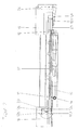
- the system shown in Fig. 1 and 2 for gluing edges on plate-shaped Workpieces include a one-sided edge banding machine 10 for banding a Edge on one side of rectangular workpieces 12, e.g. Furniture panels.
- Workpieces 12e, 12f are moved from a feed table 16 with a defined distance in the edge banding machine 10 is introduced.
- the workpieces 12e, 12f are through a provided on the inlet table 16 feed device 13 to the Feed stops attacking workpieces in the direction of the edge banding machine 10 moves, the edge to be glued on the Processing level 60 of the edge banding machine 10 is located.
- the movement of the Feed device 13 is controlled by a control device (not shown).
- a glue edge is then fed from an edge magazine 14 and into the edge banding machine 10 on one side of the rectangular workpieces 12 glued and the glue edge then in the usual way e.g. with a Cutting device, a pre-milling cutter and a fine milling cutter machined.
- a Cutting device e.g. a pre-milling cutter and a fine milling cutter machined.
- the workpieces 12 rest on passing through the edge banding machine 10 Support rollers 32 on.
- a feed device 23 with feed stops for a feed in Passage direction and a transverse displacement device 24 are provided with the Workpieces 12a, 12b, 12c, 12d perpendicular to the direction of flow on the Outlet table 18 can be moved to make room for more freshly glued To create workpieces 12 or around the plates for a handling device 20 to position.
- the movement of the feed device 23 and the transverse displacement device 24 is also controlled by the control device.
- the workpieces 12a, 12b, 12c, 12d In order to glue edges of further sides of the workpieces 12a, 12b, 12c, 12d, the workpieces 12a, 12b, 12c, 12d from the outlet table 18 to the inlet table 16 transported back and for gluing another edge by 90 ° or rotated by 180 ° again on the infeed table 16.
- the handling device 20 is provided, which is described below 3 to 8 is explained in more detail.
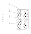
- the handling device 20 includes a recording head 30 with a horizontally arranged rectangular Bottom surface 34.
- a recording head 30 On the bottom surface 34, two are parallel to the longitudinal edges extending arrangements of vacuum suction plates 36 are provided. Any arrangement comprises four rows running parallel to the longitudinal edges of the bottom surface 34 of vacuum suction plates 36.
- the to the corresponding longitudinal edge of the bottom surface 34 adjacent row includes seven suction cups 36, which are in uniform Are spaced from each other.
- the second row comprises six vacuum suction cups 36, which is between the vacuum suction plates 36 of the first row to the center the bottom surface 34 are arranged offset.
- the third row of the Vacuum suction plate 36 is located closer to the center of the bottom surface 34 than that second row, the vacuum suction plate 36 corresponding to those of the first row are arranged.
- the vacuum suction plate 36 of the innermost row are the Vacuum suction plates 36 of the second row are arranged accordingly.
- the bottom surface 34 closes off a gripper housing 38.
- the Gripper housing 38 is a vertically extending lifting rod 40 in the middle connected, which is guided vertically displaceably in the Z direction in a lifting cylinder 42 is.
- the lifting cylinder 42 is rotatable in a rotor 44 about its vertical axis arranged.
- the rotor 44 is in the X direction, that is perpendicular to Direction of travel of the edge banding machine 10, movable on a cross rail 46 slidably mounted, which in turn with their end faces parallel to the direction of flow the edge banding machine 10 can be moved in the Y direction (FIG. 1)
- Longitudinal rails of a longitudinal portal 48 is slidably mounted.
- the longitudinal portal 48 extends over the area between the inlet table 16 and the outlet table 18 beyond.
- the vacuum suction plates 36 are each provided in the gripper housing 38 Solenoid valves connected to a vacuum device. Every solenoid valve is individually connected to the control device via a data line, so that the Control device can selectively actuate each solenoid valve to the Vacuum suction plate 36 to connect to the vacuum device or this To disconnect.
- a CCD camera 50 arranged with an image processing unit in Connection is established, which processes the signals of the CCD camera 50 and Corresponding data to the control device.
- Vacuum suction plate 36 for receiving and storing furniture panels different sizes. Only those are used to hold workpieces Vacuum suction plate activated, which is above the surface of the respective furniture panels are located. By deactivating the one assigned to a furniture panel Vacuum suction plate 36 can selectively the individual furniture plate or stored together with other furniture panels.
- the bottom surface 34 of the receiving head 30 has a size of, for example 1200 mm to 700 mm.
- the bottom surface 34 of the receiving head 30 has a size of, for example 1200 mm to 700 mm.
- four furniture panels 61, 62, 64, 66 with one Size from 450 to 600 mm, as shown in Fig. 5 and 6 in pairs at a distance are arranged to each other, all suction plates 36 except for the middle two Suction plate 36a activated each arrangement.
- the activated vacuum suction plates 36 are shown hatched.
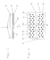
- Fig. 7 shows the activation of the vacuum suction plate 36 for receiving and storing four narrow furniture panels 70, 72, 74, 76 transverse to the longitudinal direction of the floor surface 34 and a furniture plate 78 with a size of about 600 mm by 400 mm.
- the Vacuum suction plates 36 shown in black are activated. It is clearly too recognize that only the vacuum suction plate 36 are activated, which are in the area the area of the respective furniture panels. Which is outside of this area located vacuum suction plate 36a are not activated.
- Fig. 9 finally shows the activation of individual vacuum suction plates for recording of irregular parts by a laser cutting or Water jet cutting machine have been cut.
- the workpieces 12a, 12b, 12c, 12d located on the outlet table 18 were brought two sliding mechanisms 23, 24 in the pattern shown in Fig. 1, so that the most efficient loading possible for the surface recording head 30 can be accomplished. Depending on the size of the part, these patterns are made using the Database specified and to the control device of the outlet table 18 passed.
- the finishing pattern shown in FIG. 1 is in detail in FIG. 6 played. After approval of the workpieces for takeover by the Handling device 20 can this the workpieces after driving the Record predetermined position on the suction plate 36 and the workpieces in Transport towards the infeed table 16. Depending on the edge to be glued, the Workpieces are now positioned 90 or 180 ° rotated on the feed table 16.
- the receiving head 30 After the discharge has been completed, the receiving head 30 returns to the region of the Outlet table 18 back and takes over the next at outlet table 18 finished Finished workpieces for further processing or even after finished Processing for stacking and / or for transfer to another processing station on.
- the operation of the handling device according to the invention has been based on the transport of the furniture panels from the outlet table 18 to the Inlet table 16 only explained for example.
- the handling device 20 is also suitable for furniture panels from the outlet of a panel saw or to selectively record a plate magazine and on the infeed table 16 Put edge banding machine 10 down. Already completely edged Furniture panels can be removed from the outlet table 18 and in one Clipboard or a drilling device for further processing become.
- the positioning of the furniture panels is done through a machine database coordinated, in which machine-specific and relevant processes are summarized become.
- the control device controls the Feed devices on the inlet table 16 and the outlet table 18. Also the Machining in a previous panel saw, the cuts are deposited a stack and processing in a subsequent drilling device be coordinated by the control device.
- the position of the furniture panels will when recording by the image processing unit based on the signals of the CCD camera analyzed.
- the control device can also access the data use the feed device on the outlet table. In this case the Image processing only control function.
- a barcode is placed on the surface of each workpiece for identification applied, the part-specific or order-relevant data, such as Portion size, Number, plate thickness etc. contains.
- the control device controls the individual Devices by means of optimization software, which the Sequence of the individual devices depending on the orders entered optimally coordinated.
- the suction plates 36 are like FIG. 3 distributed. There are four double rows, the two rows one Double row by 45mm in the width direction and by 90mm in the longitudinal direction are offset from one another. On an area of 1200 x 700 mm there are approx. 52 Suction plate arranged.
Applications Claiming Priority (2)
| Application Number | Priority Date | Filing Date | Title |
|---|---|---|---|
| DE20107571U DE20107571U1 (de) | 2001-05-03 | 2001-05-03 | Handhabungsvorrichtung zur Manipulation plattenförmiger Gegenstände |
| DE20107571U | 2001-05-03 |
Publications (1)
| Publication Number | Publication Date |
|---|---|
| EP1254854A1 true EP1254854A1 (fr) | 2002-11-06 |
Family
ID=7956479
Family Applications (1)
| Application Number | Title | Priority Date | Filing Date |
|---|---|---|---|
| EP02007743A Withdrawn EP1254854A1 (fr) | 2001-05-03 | 2002-04-05 | Dispositif de manutention pour des objets plat |
Country Status (2)
| Country | Link |
|---|---|
| EP (1) | EP1254854A1 (fr) |
| DE (1) | DE20107571U1 (fr) |
Cited By (10)
| Publication number | Priority date | Publication date | Assignee | Title |
|---|---|---|---|---|
| EP1529606A1 (fr) * | 2003-11-08 | 2005-05-11 | KUKA Roboter GmbH | Procédé et dispositif pour la préhension et la manipulation d'objets |
| EP1837143A1 (fr) * | 2006-03-22 | 2007-09-26 | Bernd Butzer | Machine-outil destinée au traitement de plaques |
| DE102006062528A1 (de) * | 2006-12-29 | 2008-07-03 | Deutsche Post Ag | Vorrichtung und Verfahren zur Umsetzung von Stückgut |
| CN104520029A (zh) * | 2012-08-06 | 2015-04-15 | 通快机床两合公司 | 用于将工件部分卸除的方法以及机床 |
| EP2979826A1 (fr) | 2014-07-31 | 2016-02-03 | J. Schmalz GmbH | Ventouse grande surface |
| EP3012198B1 (fr) | 2014-10-20 | 2018-01-24 | Krones Aktiengesellschaft | Dispositif et procede de manutention d'articles |
| EP3112302B1 (fr) | 2015-06-30 | 2018-05-16 | C.E.R.M.E.X. Constructions Etudes Et Recherches De Materiels Pour L'emballage D'expedition | Dispositif et methode de chargement d'un magasin |
| WO2018210993A1 (fr) * | 2017-05-19 | 2018-11-22 | Homag Plattenaufteiltechnik Gmbh | Dispositif de manipulation destiné à manipuler des marchandises plates au moins dans certaines zones, et procédé destiné à faire fonctionner un tel dispositif de manipulation |
| US10604291B2 (en) | 2014-10-20 | 2020-03-31 | Krones Aktiengesellschaft | Apparatus and method for handling articles |
| DE102014004723B4 (de) | 2014-04-01 | 2021-12-16 | Festo Se & Co. Kg | Haltevorrichtung zum Festhalten von Gegenständen |
Families Citing this family (5)
| Publication number | Priority date | Publication date | Assignee | Title |
|---|---|---|---|---|
| DE102006046624A1 (de) * | 2006-09-29 | 2008-04-03 | Brötje-Automation GmbH | Verfahren und Transportvorrichtung zum Transportieren von Gegenständen |
| IT1393111B1 (it) * | 2009-02-27 | 2012-04-11 | Raute Oyj | Alimentatore di fogli. |
| EP2886220A1 (fr) * | 2013-12-17 | 2015-06-24 | MN Coil Servicecenter GmbH | Procédé de manipulation de plaques découpées au niveau d'une machine de découpe |
| AT14110U1 (de) * | 2014-01-17 | 2015-04-15 | Grundner Sondermaschinen Gmbh | System und Vorrichtung zur gesteuerten Entnahme und Ablage von plattenförmigen Werkstücken |
| DE102014208519A1 (de) * | 2014-05-07 | 2015-11-12 | Homag Holzbearbeitungssysteme Gmbh | Bearbeitungsvorrichtung und Bearbeitungsverfahren |
Citations (4)
| Publication number | Priority date | Publication date | Assignee | Title |
|---|---|---|---|---|
| US4362461A (en) * | 1980-05-27 | 1982-12-07 | Ppg Industries, Inc. | Selective vacuum lifting device |
| US4648588A (en) * | 1985-06-12 | 1987-03-10 | Rca Corporation | Articulated manipulation device |
| EP0348311A1 (fr) * | 1988-06-24 | 1989-12-27 | Centre Technique Cuir Chaussure Maroquinerie | Dispositif pour la préhension de pièces souples isolées ou adjacentes, leur manipulation et leur dépose, notamment de pièces en cuir et similaires |
| FR2639335A1 (fr) * | 1988-11-24 | 1990-05-25 | Centre Tech Cuir Chaussure | Dispositif a elements de prehension multiples, pour la saisie d'objets isoles |
Family Cites Families (1)
| Publication number | Priority date | Publication date | Assignee | Title |
|---|---|---|---|---|
| US4252497A (en) * | 1977-08-22 | 1981-02-24 | Heico Inc. | Article handling system |
-
2001
- 2001-05-03 DE DE20107571U patent/DE20107571U1/de not_active Expired - Lifetime
-
2002
- 2002-04-05 EP EP02007743A patent/EP1254854A1/fr not_active Withdrawn
Patent Citations (4)
| Publication number | Priority date | Publication date | Assignee | Title |
|---|---|---|---|---|
| US4362461A (en) * | 1980-05-27 | 1982-12-07 | Ppg Industries, Inc. | Selective vacuum lifting device |
| US4648588A (en) * | 1985-06-12 | 1987-03-10 | Rca Corporation | Articulated manipulation device |
| EP0348311A1 (fr) * | 1988-06-24 | 1989-12-27 | Centre Technique Cuir Chaussure Maroquinerie | Dispositif pour la préhension de pièces souples isolées ou adjacentes, leur manipulation et leur dépose, notamment de pièces en cuir et similaires |
| FR2639335A1 (fr) * | 1988-11-24 | 1990-05-25 | Centre Tech Cuir Chaussure | Dispositif a elements de prehension multiples, pour la saisie d'objets isoles |
Cited By (17)
| Publication number | Priority date | Publication date | Assignee | Title |
|---|---|---|---|---|
| EP1529606A1 (fr) * | 2003-11-08 | 2005-05-11 | KUKA Roboter GmbH | Procédé et dispositif pour la préhension et la manipulation d'objets |
| EP1837143A1 (fr) * | 2006-03-22 | 2007-09-26 | Bernd Butzer | Machine-outil destinée au traitement de plaques |
| DE102006013109A1 (de) * | 2006-03-22 | 2007-09-27 | Bernd Butzer | Werkzeugmaschine zur Bearbeitung von Platten |
| DE102006013109B4 (de) * | 2006-03-22 | 2010-01-28 | Bernd Butzer | Werkzeugmaschine |
| DE102006062528A1 (de) * | 2006-12-29 | 2008-07-03 | Deutsche Post Ag | Vorrichtung und Verfahren zur Umsetzung von Stückgut |
| DE102006062528B4 (de) * | 2006-12-29 | 2011-03-31 | Deutsche Post Ag | Vorrichtung zur Umsetzung von Stückgut |
| CN104520029B (zh) * | 2012-08-06 | 2016-08-24 | 通快机床两合公司 | 用于将工件部分卸除的方法以及机床 |
| CN104520029A (zh) * | 2012-08-06 | 2015-04-15 | 通快机床两合公司 | 用于将工件部分卸除的方法以及机床 |
| DE102014004723B4 (de) | 2014-04-01 | 2021-12-16 | Festo Se & Co. Kg | Haltevorrichtung zum Festhalten von Gegenständen |
| DE102014215102A1 (de) | 2014-07-31 | 2016-02-04 | J. Schmalz Gmbh | Flächensauggreifer |
| EP2979826A1 (fr) | 2014-07-31 | 2016-02-03 | J. Schmalz GmbH | Ventouse grande surface |
| EP3012198B1 (fr) | 2014-10-20 | 2018-01-24 | Krones Aktiengesellschaft | Dispositif et procede de manutention d'articles |
| US10322833B2 (en) | 2014-10-20 | 2019-06-18 | Krones Aktiengesellschaft | Apparatus and method for handling articles |
| US10604291B2 (en) | 2014-10-20 | 2020-03-31 | Krones Aktiengesellschaft | Apparatus and method for handling articles |
| EP3012198B2 (fr) † | 2014-10-20 | 2023-07-12 | Krones Aktiengesellschaft | Dispositif et procede de manutention d'articles |
| EP3112302B1 (fr) | 2015-06-30 | 2018-05-16 | C.E.R.M.E.X. Constructions Etudes Et Recherches De Materiels Pour L'emballage D'expedition | Dispositif et methode de chargement d'un magasin |
| WO2018210993A1 (fr) * | 2017-05-19 | 2018-11-22 | Homag Plattenaufteiltechnik Gmbh | Dispositif de manipulation destiné à manipuler des marchandises plates au moins dans certaines zones, et procédé destiné à faire fonctionner un tel dispositif de manipulation |
Also Published As
| Publication number | Publication date |
|---|---|
| DE20107571U1 (de) | 2001-12-20 |
Similar Documents
| Publication | Publication Date | Title |
|---|---|---|
| EP3081343B1 (fr) | Installation de repartition de plaques et procédé destiné à repartir des pièces usinées en forme de plaques | |
| DE69922319T2 (de) | Werkstückübergabevorrichtung | |
| EP3106241B1 (fr) | Machine-outil et procédé destinés a l'évacuation de parties d'une pièce à usiner | |
| EP0737968B1 (fr) | Dispositif de transport | |
| EP1254854A1 (fr) | Dispositif de manutention pour des objets plat | |
| DE2756422C2 (de) | Fertigungsanlage für in mehreren Schritten herzustellende Bauteile | |
| DE102008017788A1 (de) | Vorrichtung zum Transportieren und Aufnehmen von Werkstückplatten sowie Verfahren zum Transportieren und Aufnehmen von Werkstückplatten | |
| DE3739405A1 (de) | Automatische zusammenbauvorrichtung | |
| DE4101904A1 (de) | Verfahren und vorrichtung zur schnittholzbearbeitung | |
| WO2016087208A1 (fr) | Équipement diviseur de panneaux pour diviser des pièces en forme de panneaux ainsi que son procédé de fonctionnement | |
| DE202013012445U1 (de) | Honmaschine mit mehreren Arbeitsstationen und Rundtisch | |
| EP2050523A1 (fr) | Agencement mécanique pour le traitement de tôle à l'aide d'un dispositif de traitement de tôle ainsi que dispositif de transport | |
| WO2015014423A1 (fr) | Procédé permettant de scier une pièce | |
| WO2015169918A2 (fr) | Dispositif d'usinage et procédé d'usinage | |
| WO1986005422A1 (fr) | Systeme de fabrication pour l'usinage automatique de pieces metalliques a usiner | |
| DE102019115634B3 (de) | Sortiersystem für eine Werkzeugmaschine, Werkzeugmaschine und Verfahren zum Sortieren von Schnittteilen | |
| EP2886220A1 (fr) | Procédé de manipulation de plaques découpées au niveau d'une machine de découpe | |
| EP4008506A1 (fr) | Système de coupe de panneaux pour scier des panneaux | |
| EP3625156B1 (fr) | Dispositif pour le stockage intermédiaire de pièces en forme de plaques | |
| EP1749627B1 (fr) | Dispositif et procédé de fabrication de panneaux de placage | |
| EP1837134A1 (fr) | Manipulateur et procédé de manipulation de pièces | |
| WO2017114632A1 (fr) | Procédé et dispositif de placement de feuilles de placage | |
| EP3922422A1 (fr) | Procédé d'usinage de pièces en forme de plaque | |
| EP2243731A1 (fr) | Dispositif de palettisation d'articles par couches | |
| DE102008061351A1 (de) | Plattentransportvorrichtung und Verfahren zu deren Steuerung |
Legal Events
| Date | Code | Title | Description |
|---|---|---|---|
| PUAI | Public reference made under article 153(3) epc to a published international application that has entered the european phase |
Free format text: ORIGINAL CODE: 0009012 |
|
| AK | Designated contracting states |
Kind code of ref document: A1 Designated state(s): AT BE CH CY DE DK ES FI FR GB GR IE IT LI LU MC NL PT SE TR |
|
| AX | Request for extension of the european patent |
Free format text: AL;LT;LV;MK;RO;SI |
|
| 17P | Request for examination filed |
Effective date: 20030428 |
|
| AKX | Designation fees paid |
Designated state(s): AT DE ES FR GB IT |
|
| 17Q | First examination report despatched |
Effective date: 20031009 |
|
| STAA | Information on the status of an ep patent application or granted ep patent |
Free format text: STATUS: THE APPLICATION IS DEEMED TO BE WITHDRAWN |
|
| 18D | Application deemed to be withdrawn |
Effective date: 20040420 |