EP1254854A1 - Handling device for plate shaped articles - Google Patents
Handling device for plate shaped articles Download PDFInfo
- Publication number
- EP1254854A1 EP1254854A1 EP02007743A EP02007743A EP1254854A1 EP 1254854 A1 EP1254854 A1 EP 1254854A1 EP 02007743 A EP02007743 A EP 02007743A EP 02007743 A EP02007743 A EP 02007743A EP 1254854 A1 EP1254854 A1 EP 1254854A1
- Authority
- EP
- European Patent Office
- Prior art keywords
- plate
- control device
- shaped objects
- head
- stored
- Prior art date
- Legal status (The legal status is an assumption and is not a legal conclusion. Google has not performed a legal analysis and makes no representation as to the accuracy of the status listed.)
- Withdrawn
Links
Images


Classifications
-
- B—PERFORMING OPERATIONS; TRANSPORTING
- B65—CONVEYING; PACKING; STORING; HANDLING THIN OR FILAMENTARY MATERIAL
- B65G—TRANSPORT OR STORAGE DEVICES, e.g. CONVEYORS FOR LOADING OR TIPPING, SHOP CONVEYOR SYSTEMS OR PNEUMATIC TUBE CONVEYORS
- B65G47/00—Article or material-handling devices associated with conveyors; Methods employing such devices
- B65G47/74—Feeding, transfer, or discharging devices of particular kinds or types
- B65G47/90—Devices for picking-up and depositing articles or materials
- B65G47/91—Devices for picking-up and depositing articles or materials incorporating pneumatic, e.g. suction, grippers
- B65G47/917—Devices for picking-up and depositing articles or materials incorporating pneumatic, e.g. suction, grippers control arrangements
-
- B—PERFORMING OPERATIONS; TRANSPORTING
- B65—CONVEYING; PACKING; STORING; HANDLING THIN OR FILAMENTARY MATERIAL
- B65G—TRANSPORT OR STORAGE DEVICES, e.g. CONVEYORS FOR LOADING OR TIPPING, SHOP CONVEYOR SYSTEMS OR PNEUMATIC TUBE CONVEYORS
- B65G2203/00—Indexing code relating to control or detection of the articles or the load carriers during conveying
- B65G2203/04—Detection means
- B65G2203/041—Camera
Definitions
- the invention relates to a handling device for manipulating plate-shaped Objects, in particular a handling device for the transport of Furniture panels, for loading and unloading an edge banding machine and / or for stacking and sorting furniture panels.
- one edge is processed in one pass on one side of a generally rectangular plate-shaped workpiece glued.
- the workpiece is therefore four times offset by 90 ° Pass through layers.
- the majority of the edges are the same on all four sides, they however, they can also be different.
- handling devices are known on their underside Have vacuum devices that are used to transport a Workpiece are activated. It is true that with such handling devices Multiple workpieces can be picked up simultaneously. A selective filing of the However, workpieces cannot be carried out with these handling devices become.
- the invention has for its object a structurally simple means Handling device for manipulating plate-shaped objects create a selective inclusion and storage of the plate-shaped Objects and which can be integrated into automation, so that a fully automatic loading and unloading process can be carried out.
- the handling device it is possible to produce a workpiece or pick up several workpieces and place them in a certain place an exact predetermined position and order at the same time or one after the other. Because both the movement of the recording head as well the selective activation and deactivation of the suction devices by the Control device is carried out, the integration of the handling device automation possible.
- Selective picking up and selective depositing is necessary in order to e.g. of a To be able to take off stacks and, depending on the optimization requirements, new ones Criteria in new order for the individual processing stations or Bring machines.
- the handling device according to the invention is, for example, for Loading, unloading and stacking of furniture panels at one Suitable for edge banding. You can use an upstream panel saw or a downstream storage or a drilling device be coordinated logistically.
- the handling device can also be used for changing edge magazines Roll edges are used in an edge banding machine. Furthermore is the handling device according to the invention also for unloading plate-shaped objects with very variable contours particularly suitable easily with a laser cutting machine or a water jet cutting machine can be generated.
- the suction devices are preferably formed by vacuum suction plates are individually connected to the control device via a serial data line.
- Detection device which is preferably formed by a camera, transmits the image signals to an image processing unit which consists of the data from the Image signals captured data about the location and size of the plate-shaped objects determined and this to the control device passes.
- a database is expediently provided for integration into logistics, in which parameters of the plate-shaped objects are stored.
- the Control device can then the movement of the recording head and Suction devices based on the stored parameters and / or by the Control image processing unit passed on data.
- the Handling device used in an edge banding machine can furthermore the way of edging and gluing details like for example the selection of the edges can be stored.
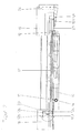
- the system shown in Fig. 1 and 2 for gluing edges on plate-shaped Workpieces include a one-sided edge banding machine 10 for banding a Edge on one side of rectangular workpieces 12, e.g. Furniture panels.
- Workpieces 12e, 12f are moved from a feed table 16 with a defined distance in the edge banding machine 10 is introduced.
- the workpieces 12e, 12f are through a provided on the inlet table 16 feed device 13 to the Feed stops attacking workpieces in the direction of the edge banding machine 10 moves, the edge to be glued on the Processing level 60 of the edge banding machine 10 is located.
- the movement of the Feed device 13 is controlled by a control device (not shown).
- a glue edge is then fed from an edge magazine 14 and into the edge banding machine 10 on one side of the rectangular workpieces 12 glued and the glue edge then in the usual way e.g. with a Cutting device, a pre-milling cutter and a fine milling cutter machined.
- a Cutting device e.g. a pre-milling cutter and a fine milling cutter machined.
- the workpieces 12 rest on passing through the edge banding machine 10 Support rollers 32 on.
- a feed device 23 with feed stops for a feed in Passage direction and a transverse displacement device 24 are provided with the Workpieces 12a, 12b, 12c, 12d perpendicular to the direction of flow on the Outlet table 18 can be moved to make room for more freshly glued To create workpieces 12 or around the plates for a handling device 20 to position.
- the movement of the feed device 23 and the transverse displacement device 24 is also controlled by the control device.
- the workpieces 12a, 12b, 12c, 12d In order to glue edges of further sides of the workpieces 12a, 12b, 12c, 12d, the workpieces 12a, 12b, 12c, 12d from the outlet table 18 to the inlet table 16 transported back and for gluing another edge by 90 ° or rotated by 180 ° again on the infeed table 16.
- the handling device 20 is provided, which is described below 3 to 8 is explained in more detail.
- the handling device 20 includes a recording head 30 with a horizontally arranged rectangular Bottom surface 34.
- a recording head 30 On the bottom surface 34, two are parallel to the longitudinal edges extending arrangements of vacuum suction plates 36 are provided. Any arrangement comprises four rows running parallel to the longitudinal edges of the bottom surface 34 of vacuum suction plates 36.
- the to the corresponding longitudinal edge of the bottom surface 34 adjacent row includes seven suction cups 36, which are in uniform Are spaced from each other.
- the second row comprises six vacuum suction cups 36, which is between the vacuum suction plates 36 of the first row to the center the bottom surface 34 are arranged offset.
- the third row of the Vacuum suction plate 36 is located closer to the center of the bottom surface 34 than that second row, the vacuum suction plate 36 corresponding to those of the first row are arranged.
- the vacuum suction plate 36 of the innermost row are the Vacuum suction plates 36 of the second row are arranged accordingly.
- the bottom surface 34 closes off a gripper housing 38.
- the Gripper housing 38 is a vertically extending lifting rod 40 in the middle connected, which is guided vertically displaceably in the Z direction in a lifting cylinder 42 is.
- the lifting cylinder 42 is rotatable in a rotor 44 about its vertical axis arranged.
- the rotor 44 is in the X direction, that is perpendicular to Direction of travel of the edge banding machine 10, movable on a cross rail 46 slidably mounted, which in turn with their end faces parallel to the direction of flow the edge banding machine 10 can be moved in the Y direction (FIG. 1)
- Longitudinal rails of a longitudinal portal 48 is slidably mounted.
- the longitudinal portal 48 extends over the area between the inlet table 16 and the outlet table 18 beyond.
- the vacuum suction plates 36 are each provided in the gripper housing 38 Solenoid valves connected to a vacuum device. Every solenoid valve is individually connected to the control device via a data line, so that the Control device can selectively actuate each solenoid valve to the Vacuum suction plate 36 to connect to the vacuum device or this To disconnect.
- a CCD camera 50 arranged with an image processing unit in Connection is established, which processes the signals of the CCD camera 50 and Corresponding data to the control device.
- Vacuum suction plate 36 for receiving and storing furniture panels different sizes. Only those are used to hold workpieces Vacuum suction plate activated, which is above the surface of the respective furniture panels are located. By deactivating the one assigned to a furniture panel Vacuum suction plate 36 can selectively the individual furniture plate or stored together with other furniture panels.
- the bottom surface 34 of the receiving head 30 has a size of, for example 1200 mm to 700 mm.
- the bottom surface 34 of the receiving head 30 has a size of, for example 1200 mm to 700 mm.
- four furniture panels 61, 62, 64, 66 with one Size from 450 to 600 mm, as shown in Fig. 5 and 6 in pairs at a distance are arranged to each other, all suction plates 36 except for the middle two Suction plate 36a activated each arrangement.
- the activated vacuum suction plates 36 are shown hatched.
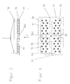
- Fig. 7 shows the activation of the vacuum suction plate 36 for receiving and storing four narrow furniture panels 70, 72, 74, 76 transverse to the longitudinal direction of the floor surface 34 and a furniture plate 78 with a size of about 600 mm by 400 mm.
- the Vacuum suction plates 36 shown in black are activated. It is clearly too recognize that only the vacuum suction plate 36 are activated, which are in the area the area of the respective furniture panels. Which is outside of this area located vacuum suction plate 36a are not activated.
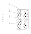
- Fig. 9 finally shows the activation of individual vacuum suction plates for recording of irregular parts by a laser cutting or Water jet cutting machine have been cut.
- the workpieces 12a, 12b, 12c, 12d located on the outlet table 18 were brought two sliding mechanisms 23, 24 in the pattern shown in Fig. 1, so that the most efficient loading possible for the surface recording head 30 can be accomplished. Depending on the size of the part, these patterns are made using the Database specified and to the control device of the outlet table 18 passed.
- the finishing pattern shown in FIG. 1 is in detail in FIG. 6 played. After approval of the workpieces for takeover by the Handling device 20 can this the workpieces after driving the Record predetermined position on the suction plate 36 and the workpieces in Transport towards the infeed table 16. Depending on the edge to be glued, the Workpieces are now positioned 90 or 180 ° rotated on the feed table 16.
- the receiving head 30 After the discharge has been completed, the receiving head 30 returns to the region of the Outlet table 18 back and takes over the next at outlet table 18 finished Finished workpieces for further processing or even after finished Processing for stacking and / or for transfer to another processing station on.
- the operation of the handling device according to the invention has been based on the transport of the furniture panels from the outlet table 18 to the Inlet table 16 only explained for example.
- the handling device 20 is also suitable for furniture panels from the outlet of a panel saw or to selectively record a plate magazine and on the infeed table 16 Put edge banding machine 10 down. Already completely edged Furniture panels can be removed from the outlet table 18 and in one Clipboard or a drilling device for further processing become.
- the positioning of the furniture panels is done through a machine database coordinated, in which machine-specific and relevant processes are summarized become.
- the control device controls the Feed devices on the inlet table 16 and the outlet table 18. Also the Machining in a previous panel saw, the cuts are deposited a stack and processing in a subsequent drilling device be coordinated by the control device.
- the position of the furniture panels will when recording by the image processing unit based on the signals of the CCD camera analyzed.
- the control device can also access the data use the feed device on the outlet table. In this case the Image processing only control function.
- a barcode is placed on the surface of each workpiece for identification applied, the part-specific or order-relevant data, such as Portion size, Number, plate thickness etc. contains.
- the control device controls the individual Devices by means of optimization software, which the Sequence of the individual devices depending on the orders entered optimally coordinated.
- the suction plates 36 are like FIG. 3 distributed. There are four double rows, the two rows one Double row by 45mm in the width direction and by 90mm in the longitudinal direction are offset from one another. On an area of 1200 x 700 mm there are approx. 52 Suction plate arranged.
Landscapes
- Engineering & Computer Science (AREA)
- Mechanical Engineering (AREA)
- Basic Packing Technique (AREA)
- Manipulator (AREA)
Abstract
Description
Die Erfindung betrifft eine Handhabungsvorrichtung zur Manipulation plattenförmiger Gegenstände, insbesondere eine Handhabungsvorrichtung für den Transport von Möbelplatten, zum Beschicken und Entladen einer Kantenanleimmaschine und/oder zum Abstapeln und Sortieren von Möbelplatten.The invention relates to a handling device for manipulating plate-shaped Objects, in particular a handling device for the transport of Furniture panels, for loading and unloading an edge banding machine and / or for stacking and sorting furniture panels.
Mit einseitigen Kantenanleimmaschinen wird in einem Durchlauf jeweils eine Kante an einer Seite eines in der Regel rechteckigen plattenförmigen Werkstücks angeleimt. Zur Anleimung einer Kante auf allen vier Seiten des Werkstückes muß das Werkstück daher die Kantenanleimmaschine viermal in um 90° versetzten Lagen durchlaufen. Die Kanten sind in der Mehrzahl an allen vier Seiten gleich, sie können jedoch auch unterschiedlich sein.With one-sided edge banding machines, one edge is processed in one pass on one side of a generally rectangular plate-shaped workpiece glued. For gluing an edge on all four sides of the workpiece the workpiece is therefore four times offset by 90 ° Pass through layers. The majority of the edges are the same on all four sides, they however, they can also be different.
Zur Werkstückrückführung ist es beispielsweise aus dem Prospekt "Werkstückrückführungen Baureihe ZHR" der Ligmatech Maschinenbau GmbH bekannt, am Auslauf einer Kantenanleimmaschine eine Hubvorrichtung vorzusehen, die ein aus der Kantenanleimmaschine auslaufendes Werkstück auf eine oberhalb der Bearbeitungsebene der Kantenanleimmaschine angeordnete Rückführbahn anhebt, die in Richtung des Einlaufes leicht geneigt ist. Antriebsrollen der Rücklaufbahn setzen das Werkstück in Bewegung. Aufgrund der Neigung rollt das Werkstück zu einer Bedienungsperson zurück, die sich am Einlauf der Kantenanleimmaschine befindet. Die Bedienungsperson nimmt dann das Werkstück von der Rücklaufbahn ab und legt es um 90° bzw. 180° versetzt in die Kantenanleimmaschine ein. Kleinere Werkstücke können auch über eine eigene Drehvorrichtung automatisch gedreht werden.For workpiece return it is from the brochure, for example "Workpiece returns series ZHR" from Ligmatech Maschinenbau GmbH known to provide a lifting device at the outlet of an edge banding machine, a workpiece that runs out of the edge banding machine onto an upper one return path arranged on the processing plane of the edge banding machine that is slightly inclined towards the inlet. Driving roles of the Return path set the workpiece in motion. Because of the inclination, it rolls Workpiece back to an operator who is at the inlet of the Edge banding machine is located. The operator then takes the workpiece from the return path and places it offset by 90 ° or 180 ° in the edge banding machine on. Smaller workpieces can also have their own Rotating device can be rotated automatically.
Darüber hinaus ist es aus einem Prospekt der Bargstedt Maschinen- und Anlagenbau GmbH bekannt, am Ende der Kantenanleimmaschine einen Riementransport mit Auszugsvorrichtung vorzusehen, der ein Werkstück am Auslauf der Kantenanleimmaschine auf einen Lufttisch befördert, der leicht geneigt ist. Das Werkstück wird durch eigene Schwerkraft und einen Lufttisch auf eine tiefere Ebene bewegt und anschließend über ein Förderband in Richtung des Einlaufes der Kantenanleimmaschine zurückbewegt. Auch bei dieser Vorrichtung wird das Werkstück von einer Bedienungsperson abgenommen und um 90° bzw. 180° versetzt wieder in die Kantenanleimmaschine eingelegt.In addition, it is from a brochure of the Bargstedt machine and Anlagenbau GmbH known, one at the end of the edge banding machine To provide belt transport with pull-out device that a workpiece on The edge banding machine's outlet is conveyed to an air table that is slightly inclined is. The workpiece is placed on one by gravity and an air table moved lower level and then on a conveyor belt in the direction of Edge of the edge banding machine moved back. Even with this device the workpiece is removed by an operator and turned by 90 ° or Relocated 180 ° in the edge banding machine.
Bei den bekannten Rückführeinrichtungen ist stets eine Bedienungsperson für ein Wiedereinlegen der Werkstücke in die Kantenanleimmaschine erforderlich. Darüber hinaus besteht keine Automatisierungs- und Einbindungsmöglichkeit in Produktionssteuersysteme. Beispielsweise müssen die Werkstücke von einer vorgeschalteten Plattensäge zur Kantenanleimmaschine befördert werden. Nachdem alle Kanten eines Werkstückes beleimt sind, muss das Werkstück von der Bedienungsperson zu einer nachfolgenden Ablage oder einer Bohrvorrichtung transportiert werden. Schließlich ist keine Einbindung in eine Logistikintelligenz möglich.In the known feedback devices, there is always an operator for one The workpieces must be reinserted into the edge banding machine. About that there is also no possibility of automation and integration in production control systems. For example, the workpieces must be upstream Panel saw are transported to the edge banding machine. After all edges of a workpiece are glued, the workpiece must be operated by the operator can be transported to a subsequent storage or drilling device. Finally, no integration into a logistics intelligence is possible.
Darüber hinaus sind Handhabungsvorrichtungen bekannt, die an ihrer Unterseite Unterdruckeinrichtungen aufweisen, die gleichzeitig zur Beförderung eines Werkstückes aktiviert werden. Zwar ist mit solchen Handhabungsvorrichtungen die gleichzeitige Aufnahme mehrerer Werkstücke möglich. Ein selektives Ablegen der Werkstücke kann mit diesen Handhabungsvorrichtungen jedoch nicht durchgeführt werden.In addition, handling devices are known on their underside Have vacuum devices that are used to transport a Workpiece are activated. It is true that with such handling devices Multiple workpieces can be picked up simultaneously. A selective filing of the However, workpieces cannot be carried out with these handling devices become.
Grundsätzlich gilt bei allen genannten Lösungen, dass eine Automatisierung nur bei sehr einheitlichem Teilespektrum im Zuge einer Massen- bzw. Seriefertigung erreicht werden kann.Basically, with all the solutions mentioned, automation only applies to very uniform range of parts in the course of mass or series production can be achieved.
Der Erfindung liegt die Aufgabe zugrunde, mit konstruktiv einfachen Mitteln eine Handhabungsvorrichtung zur Manipulation plattenförmiger Gegenstände zu schaffen, die eine selektive Aufnahme und Ablage der plattenförmigen Gegenstände ermöglicht und die in eine Automatisierung einbindbar ist, so dass eine vollautomatischer Beschick- und Entladevorgang durchgeführt werden kann. The invention has for its object a structurally simple means Handling device for manipulating plate-shaped objects create a selective inclusion and storage of the plate-shaped Objects and which can be integrated into automation, so that a fully automatic loading and unloading process can be carried out.
Diese Aufgabe wird erfindungsgemäß durch eine Handhabungsvorrichtung mit den Merkmalen des Patentanspruchs 1 gelöst.This object is achieved by a handling device with the Features of claim 1 solved.
Vorteilhafte Weiterbildungen der erfindungsgemäßen Handhabungsvorrichtung sind Gegenstand der Patentansprüche 2 bis 8.Advantageous further developments of the handling device according to the invention are Subject matter of claims 2 to 8.
Mit der erfindungsgemäßen Handhabungsvorrichtung ist es möglich, ein Werkstück oder mehrere Werkstücke gezielt aufzunehmen und an einem bestimmten Ort in einer exakten vorher bestimmten Position und Reihenfolge gleichzeitig oder nacheinander abzulegen. Da sowohl die Bewegung des Aufnahmekopfes als auch die selektive Aktivierung und Deaktivierung der Saugeinrichtungen durch die Steuereinrichtung durchgeführt wird, ist die Einbindung der Handhabungsvorrichtung in eine Automatisierung möglich.With the handling device according to the invention it is possible to produce a workpiece or pick up several workpieces and place them in a certain place an exact predetermined position and order at the same time or one after the other. Because both the movement of the recording head as well the selective activation and deactivation of the suction devices by the Control device is carried out, the integration of the handling device automation possible.
Das selektive Aufnehmen und selektive Ablegen ist nötig, um Teile z.B. von einem Stapel abzunehmen zu können und je nach Optimierungsanforderung nach neuen Kriterien in neuer Reihenfolge zu den einzelnen Bearbeitungsstationen bzw. Maschinen zu bringen.Selective picking up and selective depositing is necessary in order to e.g. of a To be able to take off stacks and, depending on the optimization requirements, new ones Criteria in new order for the individual processing stations or Bring machines.
Bei Laserschneidmaschinen oder Wasserstrahlmaschinen müssen z.B. die fertig geschnittenen Teile aus Kapazitätsgründen mehrfach von den Schneidtischen aufgenommen werden, jedoch zum Stapeln einzeln übereinander geschlichtet und damit einzeln abgelegt werden. Das selektive Ansteuern der entsprechenden Saugnäpfe bei sehr variablen Konturen ist auf einfache Weise mit einer CAD-Anbindung zu lösen.With laser cutting machines or water jet machines, e.g. the finished cut parts several times from the cutting tables for capacity reasons can be included, but individually stacked and stacked for stacking to be filed individually. The selective control of the corresponding Suction cups with very variable contours is easy with a CAD connection to solve.
Die erfindungsgemäße Handhabungsvorrichtung ist beispielsweise zum Beschicken, Entladen und Abstapeln von Möbelplatten bei einer Kantenanleimmaschine geeignet. Sie kann mit einer vorgeschalteten Plattensäge oder einer nachgeschalteten Ablage beziehungsweise einer Bohrvorrichtung logistisch koordiniert werden. The handling device according to the invention is, for example, for Loading, unloading and stacking of furniture panels at one Suitable for edge banding. You can use an upstream panel saw or a downstream storage or a drilling device be coordinated logistically.
Die Handhabungsvorrichtung kann auch zum Wechseln von Kantenmagazinen für Rollenkanten bei einer Kantenanleimmaschine verwendet werden. Darüber hinaus ist die erfindungsgemäße Handhabungsvorrichtung auch zum Entladen von plattenförmigen Gegenständen mit sehr variablen Konturen besonders geeignet, die mit einer Laserschneidemaschine oder einer Wasserstrahlschneidmaschine leicht erzeugt werden können.The handling device can also be used for changing edge magazines Roll edges are used in an edge banding machine. Furthermore is the handling device according to the invention also for unloading plate-shaped objects with very variable contours particularly suitable easily with a laser cutting machine or a water jet cutting machine can be generated.
Die Saugeinrichtungen werden bevorzugt von Vakuumsaugtellem gebildet, die einzeln über eine serielle Datenleitung mit der Steuereinrichtung verbunden sind.The suction devices are preferably formed by vacuum suction plates are individually connected to the control device via a serial data line.
Zur positionsgenauen Aufnahme und Ablage plattenförmiger Gegenstände ist in dem Aufnahmekopf bei einer bevorzugten Ausführungsform eine Erfassungseinrichtung vorgesehen, die bevorzugt von einer Kamera gebildet wird, die Bildsignale an eine Bildbearbeitungseinheit überträgt, die aus den von der Erfassungseinrichtung erfassten Bildsignalen Daten über die Lage und Größe der plattenförmigen Gegenstände ermittelt und diese an die Steuereinrichtung weitergibt.For precise positioning and storage of plate-shaped objects is in the recording head in a preferred embodiment Detection device provided, which is preferably formed by a camera, transmits the image signals to an image processing unit which consists of the data from the Image signals captured data about the location and size of the plate-shaped objects determined and this to the control device passes.
Zur Einbindung in eine Logistik ist zweckmäßigerweise eine Datenbank vorgesehen, in der Parameter der plattenförmigen Gegenstände hinterlegt sind. Die Steuereinrichtung kann dann die Bewegung des Aufnahmekopfes und die Saugeinrichtungen auf der Basis der hinterlegten Parameter und/oder der von der Bildbearbeitungseinheit weitergegebenen Daten steuern.A database is expediently provided for integration into logistics, in which parameters of the plate-shaped objects are stored. The Control device can then the movement of the recording head and Suction devices based on the stored parameters and / or by the Control image processing unit passed on data.
Als Parameter können in der Datenbank Parameter über die Art, Größe, Anzahl, Nummer und Stärke der plattenförmigen Gegenstände hinterlegt sein. Wenn die Handhabungsvorrichtung bei einer Kantenanleimmaschine verwendet wird, können darüberhinaus die Art und Weise der Bekantung und verleimtechnische Details wie zum Beispiel die Auswahl der Kanten hinterlegt werden. In the database, parameters such as type, size, number, The number and thickness of the plate-shaped objects must be stored. If the Handling device used in an edge banding machine can furthermore the way of edging and gluing details like for example the selection of the edges can be stored.
Über die Kamera und die Bildbearbeitungseinheit kann ein auf ein Werkstück angebrachter Barcode entziffert und anhand der Datenbank die Werkstückeigenschaften identifiziert werden.One can work on a workpiece via the camera and the image processing unit decoded barcode and based on the database the Workpiece properties can be identified.
Ein Ausführungsbeispiel der Erfindung wird nachstehend anhand der Zeichnung näher erläutert. Es zeigen
- Fig. 1
- eine Draufsicht auf eine Anlage zum Anleimen von Kanten auf plattenförmige Werkstücke, wobei sich eine Handhabungsvorrichtung an einem Auslauftisch befindet;
- Fig. 2
- eine Draufsicht auf die Anlage zum Anleimen von Kanten auf plattenförmige Werkstücke, wobei sich die Handhabungsvorrichtung an einem Einlauftisch befindet;
- Fig. 3
- eine Unteransicht eines Aufnahmekopfes;
- Fig. 4
- eine teilweise Seitenansicht der Handhabungsvorrichtung, die den Aufnahmekopf umfasst;
- Fig. 5
- eine Seitenansicht des Aufnahmekopfes bei einer ersten Aktivierung von Vakuumsaugtellern des Aufnahmekopfes;
- Fig. 6
- eine Unteransicht von Fig. 5;
- Fig. 7
- eine zweite Aktivierung von Vakuumsaugtellern des Aufnahmekopfes;
- Fig. 8
- eine dritte Aktivierung von Vakuumsaugtellern des Aufnahmekopfes.
- Fig. 9
- eine vierte Aktivierung von Vakuumsaugtellern des Aufnahmekopfes.
- Fig. 1
- a plan view of a system for gluing edges on plate-shaped workpieces, wherein a handling device is located on an outlet table;
- Fig. 2
- a plan view of the system for gluing edges on plate-shaped workpieces, the handling device being located on an infeed table;
- Fig. 3
- a bottom view of a recording head;
- Fig. 4
- a partial side view of the handling device comprising the pick-up head;
- Fig. 5
- a side view of the recording head during a first activation of vacuum suction plates of the recording head;
- Fig. 6
- a bottom view of Fig. 5;
- Fig. 7
- a second activation of vacuum suction cups of the pick-up head;
- Fig. 8
- a third activation of vacuum suction cups of the pick-up head.
- Fig. 9
- a fourth activation of suction cups of the pick-up head.
Die in Fig. 1 und 2 gezeigte Anlage zum Anleimen von Kanten auf plattenförmige
Werkstücke umfasst eine einseitige Kantenanleimmaschine 10 zum Anleimen einer
Kante auf eine Seite von rechteckigen Werkstücken 12, wie z.B. Möbelplatten.The system shown in Fig. 1 and 2 for gluing edges on plate-shaped
Workpieces include a one-sided
Werkstücke 12e, 12f werden von einem Einlauftisch 16 mit definiertem Abstand in
die Kantenanleimmaschine 10 eingeführt. Die Werkstücke 12e, 12f werden durch
eine am Einlauftisch 16 vorgesehene Vorschubvorrichtung 13 mit an den
Werkstücken angreifenden Vorsschubanschlägen in Richtung der Kantenanleimmaschine
10 bewegt, wobei sich die zu beleimende Kante auf dem
Bearbeitungsniveau 60 der Kantenanleimmaschine 10 befindet. Die Bewegung der
Vorschubvorrichtung 13 wird durch eine Steuereinrichtung (nicht gezeigt) gesteuert.
Anschließend wird eine Anleimkante von einem Kantenmagazin 14 zugeführt und in
der Kantenanleimmaschine 10 auf eine Seite der rechteckigen Werkstücke 12
angeleimt und die Anleimkante dann auf übliche Weise z.B. mit einer
Kappeinrichtung, einem Vorfräser und einem Feinfräser bearbeitet. Während des
Durchlaufs durch die Kantenanleimmaschine 10 liegen die Werkstücke 12 auf
Unterstützungsrollen 32 auf. Nach der Bearbeitung in der Kantenanleimmaschine
werden die Werkstücke 12 aus der Kantenanleimmaschine 10 in deren
Durchlaufrichtung auf einen Auslauftisch 18 befördert. An dem Auslauftisch 18 ist
eine Vorschubvorrichtung 23 mit Vorschubanschlägen für einen Vorschb in
Durchlaufrichtung und eine Querverschiebevorrichtung 24 vorgesehen, mit dem
Werkstücke 12a, 12b, 12c, 12d senkrecht zur Durchlaufrichtung auf dem
Auslauftisch 18 verschoben werden können, um Platz für weitere frisch beleimte
Werkstücke 12 zu schaffen bzw. um die Platten für eine Handhabungsvorrichtung
20 zu positionieren. Die Bewegung der Vorschubvorrichtung 23 und der Querverschiebevorrichtung
24 wird ebenfalls von der Steuereinrichtung gesteuert.A glue edge is then fed from an
Um weitere Seiten der Werkstücke 12a, 12b, 12c, 12d mit einer Kante zu beleimen,
müssen die Werkstücke 12a, 12b, 12c, 12d von dem Auslauftisch 18 zu dem Einlauftisch
16 zurückbefördert und zur Beleimung einer weiteren Kante um 90°
beziehungsweise 180° verdreht wieder auf dem Einlauftisch 16 abgelegt werden.
Hierzu ist die Handhabungsvorrichtung 20 vorgesehen, die nachstehend anhand
der Fig. 3 bis 8 näher erläutert wird.In order to glue edges of further sides of the
Wie es in den Fig. 3 und 4 gezeigt ist, umfasst die Handhabungsvorrichtung 20
einen Aufnahmekopf 30 mit einer horizontal angeordneten rechteckigen
Bodenfläche 34. An der Bodenfläche 34 sind zwei parallel zu den Längsrändern
verlaufende Anordnungen von Vakuumsaugtellern 36 vorgesehen. Jede Anordnung
umfaßt vier parallel zu den Längsrändern der Bodenfläche 34 verlaufende Reihen
von Vakuumsaugtellern 36. Die an den entsprechenden Längsrand der Bodenfläche
34 angrenzende Reihe umfasst sieben Vakuumsaugteller 36, die in gleichmäßigem
Abstand zueinander angeordnet sind. Die zweite Reihe umfasst sechs Vakuumsaugteller
36, die zwischen den Vakuumsaugtellern 36 der ersten Reihe zur Mitte
der Bodenfläche 34 hin versetzt angeordnet sind. Die dritte Reihe der
Vakuumsaugteller 36 ist näher zur Mitte der Bodenfläche 34 angeordnet, als die
zweite Reihe, wobei die Vakuumsaugteller 36 denen der ersten Reihe entsprechend
angeordnet sind. Die Vakuumsaugteller 36 der innersten Reihe sind den
Vakuumsaugtellern 36 der zweiten Reihe entsprechend angeordnet.As shown in FIGS. 3 and 4, the handling
Die Bodenfläche 34 schließt ein Greifergehäuse 38 nach unten ab. Mit dem
Greifergehäuse 38 ist mittig eine sich vertikal erstreckende Hubstange 40
verbunden, die in einem Hubzylinder 42 vertikal in Z-Richtung verschiebbar geführt
ist. Der Hubzylinder 42 ist in einem Läufer 44 um seine vertikale Achse drehbar
angeordnet. Der Läufer 44 ist in X-Richtung, das heißt senkrecht zur
Durchlaufrichtung der Kantenanleimmaschine 10, verfahrbar an einer Querschiene
46 verschiebbar gelagert, die ihrerseits mit ihren Stirnseiten parallel zur Durchlaufrichtung
der Kantenanleimmaschine 10 in Y-Richtung (Fig. 1) verfahrbar auf
Längsschienen eines Längsportal 48 verschiebbar gelagert ist. Das Längsportal 48
erstreckt sich über den Bereich zwischen dem Einlauftisch 16 und dem Auslauftisch
18 hinaus.The
Aufgrund der oben beschriebenen Konstruktion wird die Bewegung des
Aufnahmekopfes 30 mit Hilfe von jeweiligen Antriebsmotoren über vier Achsen (X-,
Y-, Z-Achse und Drehachse) durch die Steuereinrichtung über eine entsprechende
Achseninterpolation ausgeführt.Due to the construction described above, the movement of the
Pick-up
Die Vakuumsaugteller 36 sind jeweils über im Greifergehäuse 38 vorgesehene
Magnetventile mit einer Unterdruckeinrichtung verbunden. Jedes Magnetventil ist
einzeln über eine Datenleitung mit der Steuereinrichtung verbunden, so dass die
Steuereinrichtung jedes Magnetventil selektiv betätigen kann, um die
Vakuumsaugteller 36 mit der Unterdruckeinrichtung zu verbinden oder diese
Verbindung zu unterbrechen. The
Wie es in Fig. 3 gezeigt ist, ist zentral in der Bodenfläche 34 des Aufnahmekopfes
30 eine CCD-Kamera 50 angeordnet, die mit einer Bildverarbeitungseinheit in
Verbindung steht, die die Signale der CCD-Kamera 50 verarbeitet und
entsprechende Daten an die Steuereinrichtung weitergibt.As shown in Fig. 3, is central in the
Die Fig. 5 bis 8 zeigen verschiedene Beispiele der Aktivierung der
Vakuumsaugteller 36 zur Aufnahme und zum Ablegen von Möbelplatten
unterschiedlicher Größe. Zur Aufnahme von Werkstücken werden jeweils nur die
Vakuumsaugteller aktiviert, die sich oberhalb der Fläche der jeweiligen Möbelplatten
befinden. Durch Deaktivierung der einer Möbelplatte zugeordneten
Vakuumsaugteller 36 kann die entsprechende Möbelplatte selektiv einzeln oder
zusammen mit anderen Möbelplatten abgelegt werden.5 to 8 show various examples of the activation of the
Die Bodenfläche 34 des Aufnahmekopfes 30 hat beispielsweise eine Größe von
1200 mm auf 700 mm. Zur Aufnahme von vier Möbelplatten 61, 62, 64, 66 mit einer
Größe von 450 auf 600 mm, die wie in Fig. 5 und 6 gezeigt paarweise im Abstand
zueinander angeordnet sind, werden alle Saugteller 36 bis auf die mittleren zwei
Saugteller 36a jeder Anordnung aktiviert. Die aktivierten Vakuumsaugteller 36 sind
schraffiert dargestellt.The
Fig. 7 zeigt die Aktivierung der Vakuumsaugteller 36 zur Aufnahme und Ablage von
vier schmalen Möbelplatten 70, 72, 74, 76 quer zur Längsrichtung der Bodenfläche
34 und einer Möbelplatte 78 mit einer Größe von etwa 600 mm auf 400 mm. Die
schwarz dargestellen Vakuumsaugteller 36 sind aktiviert. Es ist deutlich zu
erkennen, daß nur die Vakuumsaugteller 36 aktiviert werden, die sich im Bereich
der Fläche der jeweiligen Möbelplatten befinden. Die sich außerhalb dieses Bereiches
befindlichen Vakuumsaugteller 36a sind nicht aktiviert.Fig. 7 shows the activation of the
Fig. 8 zeigt die Aktivierung aller Vakuumsaugteller 36 zur Aufnahme einer
Möbelplatte, deren Fläche größer ist als die der Bodenfläche 34. 8 shows the activation of all
Fig. 9 zeigt schließlich die Aktivierung einzelner Vakuumsaugteller zur Aufnahme von unregelmäßigen Teilen, die von einer Laserschneid- bzw. einer Wasserstrahlschneidmaschine geschnitten worden sind.Fig. 9 finally shows the activation of individual vacuum suction plates for recording of irregular parts by a laser cutting or Water jet cutting machine have been cut.
Die Funktionsweise der Handhabungsvorrichtung 20 wird nachstehend anhand
eines Beispiels erläutert, bei dem Möbelplatten 12a, 12b, 12c, 12d am Auslauftisch
18 der Kantenanleimmaschine 10 von der Handhabungsvorrichtung 20 abgehoben
und am Einlauftisch 16 um 180° gedreht abgelegt werden, damit eine Kante auf die
Seite der Möbelplatten 12a, 12b, 12c, 12d aufgeleimt werden kann, die der Seite
gegenüberliegt, die im vorhergehenden Bearbeitungszyklus angeleimt wurde.The operation of the handling
Es wird davon ausgegangen, dass auf dem Auslauftisch vier Möbelplatten 12a, 12b,
12c, 12d in parallelen Paaren senkrecht zur Durchlaufrichtung der Kantenanleimmaschine
10 nacheinander angeordnet sind. Zwei Möbelplatten 12e, 12f
liegen am Einlauftisch 16 in geringem Abstand in Durchlaufrichtung gesehen
nebeneinander, wobei sich die zu beleimende Kante auf dem Bearbeitungsniveau
60 der Kantenanleimmaschine 10 befindet. Die Möbelplatten 12e, 12f werden in
definiertem Abstand durch die am Einlauftisch 16 vorgesehenen
Vorschubanschläge der Vorschubvorrichtung 13 in Richtung der Kantenanleimmaschine
10 bewegt, wobei ihre Position durch die Steuereinrichtung bestimmt
wird.It is assumed that four
Die am Auslauftisch 18 befindlichen Werkstücke 12a, 12b, 12c, 12d wurden von den
beiden Schiebemechanismen 23, 24 in das in Fig. 1 gezeigte Muster gebracht, so
dass für den Flächenaufnahmekopf 30 eine möglichst effiziente Beladung
bewerkstelligt werden kann. Diese Muster werden je nach Teilegröße über die
Datenbank vorgegeben und an die Steuereinrichtung des Auslauftisches 18
weitergegeben. Das in Fig. 1 gezeigte Schlichtmuster ist im Detail in Fig. 6
wiedergegeben. Nach Freigeben der Werkstücke zur Übernahme durch die
Handhabungsvorrichtung 20 kann diese die Werkstücke nach Ansteuern der
vorgegebenen Position über die Saugteller 36 aufnehmen und die Werkstücke in
Richtung Einlauftisch 16 transportieren. Je nach zu beleimender Kante müssen die
Werkstücke nun 90 bzw. 180° gedreht auf dem Einlauftisch 16 positioniert werden. The
Dabei werden sie so hintereinander durch selektive Deaktivierung der Saugteller 36
abgelegt, dass die Werkstücke einzeln in bestimmten Abstand durch die Anschläge
13 des Einlauftisches 16 erfasst werden und auch in einem bestimmten Abstand in
die Kantenleimmaschine 10 eingebracht werden können.They are thus one after the other by selective deactivation of the
Nach fertiger Entladung kehrt der Aufnahmekopf 30 in den Bereich des
Auslauftisches 18 zurück und übernimmt dort die nächsten am Auslauftisch 18 fertig
geschlichteten Werkstücke zur weiteren Bearbeitung oder auch nach fertiger
Bearbeitung zum Stapeln und/oder zur Übergabe an eine weitere Bearbeitungsstation
auf.After the discharge has been completed, the receiving
Die Funktionsweise der erfindungsgemäßen Handhabungsvorrichtung wurde
anhand des Transportes der Möbelplatten von dem Auslauftisch 18 zu dem
Einlauftisch 16 nur beispielsweise erläutert. Die Handhabungsvorrichtung 20 ist
darüber hinaus geeignet, Möbelplatten von dem Auslauf einer Plattensäge oder
einem Plattenmagazin selektiv aufzunehmen und auf dem Einlauftisch 16 der
Kantenanleimmaschine 10 abzulegen. Bereits vollständig mit einer Kante versehene
Möbelplatten können von dem Auslauftisch 18 abgenommen und in einer
Zwischenablage oder einer Bohrvorrichtung zur weiteren Bearbeitung abgelegt
werden.The operation of the handling device according to the invention has been
based on the transport of the furniture panels from the outlet table 18 to the
Inlet table 16 only explained for example. The handling
Die Positionierung der Möbelplatten wird durch eine Maschinendatenbank
koordiniert, in der maschinenspezifische und -relevante Abläufe zusammengefasst
werden. Die Steuereinrichtung steuert neben der Handhabungsvorrichtung 20 die
Vorschubvorrichtungen an dem Einlauftisch 16 und dem Auslauftisch 18. Auch die
Bearbeitung in einer vorhergehenden Plattensäge, die Ablage der Zuschnitte auf
einem Stapel und die Bearbeitung in einer nachfolgenden Bohrvorrichtung kann
durch die Steuereinrichtung koordiniert werden. Die Position der Möbelplatten wird
beim Aufnehmen durch die Bildverarbeitungseinheit anhand der Signale der CCD-Kamera
analysiert. Die Steuereinrichtung kann darüber hinaus auch auf die Daten
der Vorschubvorrichtung am Auslauftisch zurückgreifen. In diesem Fall hat die
Bildverarbeitung lediglich Kontrollfunktion. The positioning of the furniture panels is done through a machine database
coordinated, in which machine-specific and relevant processes are summarized
become. In addition to the
Zur Identifizierung wird auf der Oberfläche jedes Werkstücks ein Barcode aufgebracht, der teilespezifische bzw. auftragsrelevante Daten, wie z.B. Teilegröße, Anzahl, Plattenstärke etc. enthält. Die Steuereinrichtung steuert die einzelnen Vorrichtungen mittels einer Optimierungssoftware, die anhand der Datenbanken den Ablauf der einzelnen Vorrichtungen in Abhängigkeit von eingegebenen Aufträgen optimal koordiniert.A barcode is placed on the surface of each workpiece for identification applied, the part-specific or order-relevant data, such as Portion size, Number, plate thickness etc. contains. The control device controls the individual Devices by means of optimization software, which the Sequence of the individual devices depending on the orders entered optimally coordinated.
Bei einem optimalen Raster für die Möbelindustrie sind die Saugteller 36 wie Fig. 3
verteilt. Es sind vier Doppelreihen vorgesehen, wobei die beiden Reihen einer
Doppelreihe um 45mm in Breitenrichtung und um 90 mm in Längsrichtung
zueinander versetzt sind. Auf einer Fläche von 1200 x 700 mm sind somit ca. 52
Saugteller angeordnet.With an optimal grid for the furniture industry, the
Claims (11)
Applications Claiming Priority (2)
| Application Number | Priority Date | Filing Date | Title |
|---|---|---|---|
| DE20107571U | 2001-05-03 | ||
| DE20107571U DE20107571U1 (en) | 2001-05-03 | 2001-05-03 | Handling device for manipulating plate-shaped objects |
Publications (1)
| Publication Number | Publication Date |
|---|---|
| EP1254854A1 true EP1254854A1 (en) | 2002-11-06 |
Family
ID=7956479
Family Applications (1)
| Application Number | Title | Priority Date | Filing Date |
|---|---|---|---|
| EP02007743A Withdrawn EP1254854A1 (en) | 2001-05-03 | 2002-04-05 | Handling device for plate shaped articles |
Country Status (2)
| Country | Link |
|---|---|
| EP (1) | EP1254854A1 (en) |
| DE (1) | DE20107571U1 (en) |
Cited By (10)
| Publication number | Priority date | Publication date | Assignee | Title |
|---|---|---|---|---|
| EP1529606A1 (en) * | 2003-11-08 | 2005-05-11 | KUKA Roboter GmbH | Method and device for gripping and handling objects |
| EP1837143A1 (en) * | 2006-03-22 | 2007-09-26 | Bernd Butzer | Machine tool for machining boards |
| DE102006062528A1 (en) * | 2006-12-29 | 2008-07-03 | Deutsche Post Ag | Bulk material moving device, has gripping device movable in vertical and horizontal directions, and including control unit for sequential withdrawal of gripping effect of gripping elements, according to fixed pattern |
| CN104520029A (en) * | 2012-08-06 | 2015-04-15 | 通快机床两合公司 | Method for removing a workpiece part and machine tool |
| EP2979826A1 (en) | 2014-07-31 | 2016-02-03 | J. Schmalz GmbH | Large-scale suction grabber |
| EP3012198B1 (en) | 2014-10-20 | 2018-01-24 | Krones Aktiengesellschaft | Device and method for handling items |
| EP3112302B1 (en) | 2015-06-30 | 2018-05-16 | C.E.R.M.E.X. Constructions Etudes Et Recherches De Materiels Pour L'emballage D'expedition | Device and method for loading a magazine |
| WO2018210993A1 (en) * | 2017-05-19 | 2018-11-22 | Homag Plattenaufteiltechnik Gmbh | Handling device for handling articles that are flat at least in some sections and method for operating such a handling device |
| US10604291B2 (en) | 2014-10-20 | 2020-03-31 | Krones Aktiengesellschaft | Apparatus and method for handling articles |
| DE102014004723B4 (en) | 2014-04-01 | 2021-12-16 | Festo Se & Co. Kg | Holding device for holding objects |
Families Citing this family (5)
| Publication number | Priority date | Publication date | Assignee | Title |
|---|---|---|---|---|
| DE102006046624A1 (en) * | 2006-09-29 | 2008-04-03 | Brötje-Automation GmbH | Method and transport device for transporting objects |
| IT1393111B1 (en) * | 2009-02-27 | 2012-04-11 | Raute Oyj | SHEET FEEDER. |
| EP2886220A1 (en) * | 2013-12-17 | 2015-06-24 | MN Coil Servicecenter GmbH | Method for handling plate-shaped cut material on a cutting machine |
| AT14110U1 (en) * | 2014-01-17 | 2015-04-15 | Grundner Sondermaschinen Gmbh | System and device for the controlled removal and storage of plate-shaped workpieces |
| DE102014208519A1 (en) * | 2014-05-07 | 2015-11-12 | Homag Holzbearbeitungssysteme Gmbh | Processing device and processing method |
Citations (4)
| Publication number | Priority date | Publication date | Assignee | Title |
|---|---|---|---|---|
| US4362461A (en) * | 1980-05-27 | 1982-12-07 | Ppg Industries, Inc. | Selective vacuum lifting device |
| US4648588A (en) * | 1985-06-12 | 1987-03-10 | Rca Corporation | Articulated manipulation device |
| EP0348311A1 (en) * | 1988-06-24 | 1989-12-27 | Centre Technique Cuir Chaussure Maroquinerie | Device for gripping isolated or adjacent flexible pieces, their manipulation and their depositing, particularly pieces of leather and the like |
| FR2639335A1 (en) * | 1988-11-24 | 1990-05-25 | Centre Tech Cuir Chaussure | Device with multiple grasping elements for seizing isolated objects |
Family Cites Families (1)
| Publication number | Priority date | Publication date | Assignee | Title |
|---|---|---|---|---|
| US4252497A (en) * | 1977-08-22 | 1981-02-24 | Heico Inc. | Article handling system |
-
2001
- 2001-05-03 DE DE20107571U patent/DE20107571U1/en not_active Expired - Lifetime
-
2002
- 2002-04-05 EP EP02007743A patent/EP1254854A1/en not_active Withdrawn
Patent Citations (4)
| Publication number | Priority date | Publication date | Assignee | Title |
|---|---|---|---|---|
| US4362461A (en) * | 1980-05-27 | 1982-12-07 | Ppg Industries, Inc. | Selective vacuum lifting device |
| US4648588A (en) * | 1985-06-12 | 1987-03-10 | Rca Corporation | Articulated manipulation device |
| EP0348311A1 (en) * | 1988-06-24 | 1989-12-27 | Centre Technique Cuir Chaussure Maroquinerie | Device for gripping isolated or adjacent flexible pieces, their manipulation and their depositing, particularly pieces of leather and the like |
| FR2639335A1 (en) * | 1988-11-24 | 1990-05-25 | Centre Tech Cuir Chaussure | Device with multiple grasping elements for seizing isolated objects |
Cited By (17)
| Publication number | Priority date | Publication date | Assignee | Title |
|---|---|---|---|---|
| EP1529606A1 (en) * | 2003-11-08 | 2005-05-11 | KUKA Roboter GmbH | Method and device for gripping and handling objects |
| EP1837143A1 (en) * | 2006-03-22 | 2007-09-26 | Bernd Butzer | Machine tool for machining boards |
| DE102006013109A1 (en) * | 2006-03-22 | 2007-09-27 | Bernd Butzer | Machine tool for processing plates |
| DE102006013109B4 (en) * | 2006-03-22 | 2010-01-28 | Bernd Butzer | machine tool |
| DE102006062528A1 (en) * | 2006-12-29 | 2008-07-03 | Deutsche Post Ag | Bulk material moving device, has gripping device movable in vertical and horizontal directions, and including control unit for sequential withdrawal of gripping effect of gripping elements, according to fixed pattern |
| DE102006062528B4 (en) * | 2006-12-29 | 2011-03-31 | Deutsche Post Ag | Device for the implementation of general cargo |
| CN104520029B (en) * | 2012-08-06 | 2016-08-24 | 通快机床两合公司 | For by the method for workpiece portion removal and lathe |
| CN104520029A (en) * | 2012-08-06 | 2015-04-15 | 通快机床两合公司 | Method for removing a workpiece part and machine tool |
| DE102014004723B4 (en) | 2014-04-01 | 2021-12-16 | Festo Se & Co. Kg | Holding device for holding objects |
| DE102014215102A1 (en) | 2014-07-31 | 2016-02-04 | J. Schmalz Gmbh | area vacuum |
| EP2979826A1 (en) | 2014-07-31 | 2016-02-03 | J. Schmalz GmbH | Large-scale suction grabber |
| EP3012198B1 (en) | 2014-10-20 | 2018-01-24 | Krones Aktiengesellschaft | Device and method for handling items |
| US10322833B2 (en) | 2014-10-20 | 2019-06-18 | Krones Aktiengesellschaft | Apparatus and method for handling articles |
| US10604291B2 (en) | 2014-10-20 | 2020-03-31 | Krones Aktiengesellschaft | Apparatus and method for handling articles |
| EP3012198B2 (en) † | 2014-10-20 | 2023-07-12 | Krones Aktiengesellschaft | Device and method for handling items |
| EP3112302B1 (en) | 2015-06-30 | 2018-05-16 | C.E.R.M.E.X. Constructions Etudes Et Recherches De Materiels Pour L'emballage D'expedition | Device and method for loading a magazine |
| WO2018210993A1 (en) * | 2017-05-19 | 2018-11-22 | Homag Plattenaufteiltechnik Gmbh | Handling device for handling articles that are flat at least in some sections and method for operating such a handling device |
Also Published As
| Publication number | Publication date |
|---|---|
| DE20107571U1 (en) | 2001-12-20 |
Similar Documents
| Publication | Publication Date | Title |
|---|---|---|
| EP3081343B1 (en) | Plate partitioning facility and method for partitioning plate-shaped workpieces | |
| DE69922319T2 (en) | Workpiece transfer device | |
| EP3106241B1 (en) | Machine tool and method for discharging workpiece parts | |
| DE69805763T2 (en) | PANEL SAWING METHOD AND MACHINE WITH PANEL SLIDER MOVABLE IN SIDE DIRECTION | |
| EP0737968B1 (en) | Transport device | |
| EP1254854A1 (en) | Handling device for plate shaped articles | |
| DE2756422C2 (en) | Production system for components to be produced in several steps | |
| DE102008017788A1 (en) | Device for transporting and picking up workpiece plates and method for transporting and picking up workpiece plates | |
| DE3739405A1 (en) | AUTOMATIC ASSEMBLY DEVICE | |
| DE4101904A1 (en) | METHOD AND DEVICE FOR PROCESSING WOOD | |
| WO2016087208A1 (en) | Plate-dividing system for dividing plate-like workpieces, and method for the operation thereof | |
| DE202013012445U1 (en) | Honing machine with several workstations and rotary table | |
| EP0252084B1 (en) | Fabrication system for the automatic working of metal workpieces | |
| DE102019115634B3 (en) | Sorting system for a machine tool, machine tool and method for sorting cut parts | |
| DE69223057T2 (en) | Vacuum clamping board for a numerically controlled milling machine | |
| EP2886220A1 (en) | Method for handling plate-shaped cut material on a cutting machine | |
| EP4008506A1 (en) | Panel cutting system for sawing workpieces | |
| EP3625156B1 (en) | Device for the intermediate storage of plate-like workpieces | |
| EP1749627B1 (en) | Apparatus and method for manufacturing veneer panels | |
| EP1837134A1 (en) | Manipulator and process for manipulating workpieces | |
| WO2017114632A1 (en) | Method and device for laying veneer panels | |
| DE20108373U1 (en) | Exit table for an edge banding machine | |
| EP3922422A1 (en) | Method for processing plate-shaped workpieces | |
| EP2243731A1 (en) | Device for palletizing articles layer by layer | |
| DE102008061351A1 (en) | Plate transport device for transporting machined plate from e.g. laser machining device, has movable load platform control device designed such that position of movable load platform corresponds to position of movable frame |
Legal Events
| Date | Code | Title | Description |
|---|---|---|---|
| PUAI | Public reference made under article 153(3) epc to a published international application that has entered the european phase |
Free format text: ORIGINAL CODE: 0009012 |
|
| AK | Designated contracting states |
Kind code of ref document: A1 Designated state(s): AT BE CH CY DE DK ES FI FR GB GR IE IT LI LU MC NL PT SE TR |
|
| AX | Request for extension of the european patent |
Free format text: AL;LT;LV;MK;RO;SI |
|
| 17P | Request for examination filed |
Effective date: 20030428 |
|
| AKX | Designation fees paid |
Designated state(s): AT DE ES FR GB IT |
|
| 17Q | First examination report despatched |
Effective date: 20031009 |
|
| STAA | Information on the status of an ep patent application or granted ep patent |
Free format text: STATUS: THE APPLICATION IS DEEMED TO BE WITHDRAWN |
|
| 18D | Application deemed to be withdrawn |
Effective date: 20040420 |