EP1253374A2 - Vehicle headlamp - Google Patents
Vehicle headlamp Download PDFInfo
- Publication number
- EP1253374A2 EP1253374A2 EP02008550A EP02008550A EP1253374A2 EP 1253374 A2 EP1253374 A2 EP 1253374A2 EP 02008550 A EP02008550 A EP 02008550A EP 02008550 A EP02008550 A EP 02008550A EP 1253374 A2 EP1253374 A2 EP 1253374A2
- Authority
- EP
- European Patent Office
- Prior art keywords
- reflector
- end section
- sections
- sheet metal
- support arm
- Prior art date
- Legal status (The legal status is an assumption and is not a legal conclusion. Google has not performed a legal analysis and makes no representation as to the accuracy of the status listed.)
- Granted
Links
Images

Classifications
-
- F—MECHANICAL ENGINEERING; LIGHTING; HEATING; WEAPONS; BLASTING
- F21—LIGHTING
- F21S—NON-PORTABLE LIGHTING DEVICES; SYSTEMS THEREOF; VEHICLE LIGHTING DEVICES SPECIALLY ADAPTED FOR VEHICLE EXTERIORS
- F21S41/00—Illuminating devices specially adapted for vehicle exteriors, e.g. headlamps
- F21S41/40—Illuminating devices specially adapted for vehicle exteriors, e.g. headlamps characterised by screens, non-reflecting members, light-shielding members or fixed shades
- F21S41/43—Illuminating devices specially adapted for vehicle exteriors, e.g. headlamps characterised by screens, non-reflecting members, light-shielding members or fixed shades characterised by the shape thereof
-
- F—MECHANICAL ENGINEERING; LIGHTING; HEATING; WEAPONS; BLASTING
- F21—LIGHTING
- F21S—NON-PORTABLE LIGHTING DEVICES; SYSTEMS THEREOF; VEHICLE LIGHTING DEVICES SPECIALLY ADAPTED FOR VEHICLE EXTERIORS
- F21S41/00—Illuminating devices specially adapted for vehicle exteriors, e.g. headlamps
- F21S41/40—Illuminating devices specially adapted for vehicle exteriors, e.g. headlamps characterised by screens, non-reflecting members, light-shielding members or fixed shades
- F21S41/47—Attachment thereof
Definitions
- the invention relates to a headlight for vehicles with a plastic manufactured bowl-shaped reflector, with a inside of the reflector arranged light source and with an aperture, which in the light exit direction seen after the light source is arranged, is made of sheet metal and at least one support arm with one composed of two parts has free end portion which engages in a reflector opening and the and the reflector opening tapers in the direction of insertion of the end section.
- Such a headlight for vehicles is known from EP 0 636 821 B1.
- the headlight cover is made in one piece from a sheet metal blank.
- An annular diaphragm section of the diaphragm is in the light exit direction seen arranged after the light source and has a seam from which extends a double support arm to the outside.
- the support arm points with its free end section against the light exit direction and is in a reflector opening formed by a hollow cylinder of the reflector used, which is closed towards the back of the reflector.
- the double End section of the support arm consists of U-shaped in cross section Sections that lie together with their side faces and together form one Form a gutter open to the outside.
- the U-shaped end section digs when pressed into the reflector opening with sawtooth-shaped edges into the inside of the reflector opening. This creates fine chips that can deposit on the decorative reflective surface of the reflector and can be seen through a smooth lens.
- the support arm engages with the sawtooth-shaped edges of its end section Flattening the inside of the reflector opening and is due to one of the Hollow cylinder of the reflector formed stop so that the aperture after Your assembly takes a precise position to the reflector.
- a middle section of the double plate-shaped End section forms a cavity formed by two indented grooves is.
- the channels or the cavity tapers in the direction of insertion Support arm.
- the support arm is with the end section having the cavity self-locking inserted in the reflector opening and in this position angled free ends on the back of the reflector securely in the reflector opening held.
- the reflector opening corresponds to the plate-shaped End section a rectangular cross section with an enlarged middle section. Only through the rectangular cross section of the reflector opening is the cover takes one and the same position after assembly to the optical axis of the reflector.
- the reflector opening is because of it rectangular shape disturbing through a smooth lens to see.
- the service life of the reflector tool is also reduced because of the narrow areas of the rectangular reflector opening.
- the object of the invention is that described in the preamble of claim 1 Design headlights for vehicles so that the bezel too is then securely fixable in the reflector opening if the Aperture in the reflector opening receiving the end section of the support arm there is no material abrasion and the reflector opening remains the size of the can be adapted in the end portion used in the reflector opening and the aperture is aligned with the optical axis of the reflector after assembly is.
- the end section consists of two half-shells forming a cavity, the seams of which run in the direction of insertion, one of which seam from radial to internally directed edge sections is formed and the other interface through a flattening of the hollow end section extends to which a surface section runs adjacent to the inside of the reflector opening. Because the Edge sections are directed inwards at one interface and at the the other face, the end faces of the half-shells lie bluntly in front of each other, there can be no abrasion in the reflector opening. Due to the conical design the outer surface of the end section is a self-locking tight fit of the support arm in the reflector opening.
- the Reflector opening is a through hole from which on the back of the Reflector of the hollow end portion with at least one to the outer edge area the free end deformed towards the reflector opening, the support arm with a contact surface in the direction of insertion on a stop surface of the reflector.
- the conical end section lies in this position its radial spring force with a large preload on the inner surface the conical reflector opening.
- the free ends are punched out of the end section so that after bending under Apply bias to the edge area of the reflector opening.
- the cover and its support arm has a high rigidity when the cover consists in one piece of a shaped sheet metal blank, one around the optical Annular aperture section of the reflector runs around the axis with a seam, from the edges of sheet metal sections to the outside protrude, lie flat against each other and form the support arm and continue the two half-shells of the hollow end section are in the flat against each other
- Extend sheet metal sections in the area of the double sheet metal sections taper together against the direction of insertion and into the merging sheet metal sections lying flat against one another.
- the conical end section together with the double sheet section high rigidity.
- the headlight shown in the drawing has an existing plastic bowl-shaped reflector 1 with one in the apex region of the reflector 1 introduced opening for receiving a light source 2.
- the light source 2 can be formed by an incandescent lamp or a gas discharge lamp his.
- An aperture 3 is arranged after the light source 2 in the light exit direction, which emerges directly from the light source 2 and otherwise the oncoming traffic shields dazzling rays of light.
- the aperture 3 has an optical Axis of the reflector 1 concentric annular aperture section 16 on.
- the annular diaphragm section 16 has in the lower region a seam 17, from which one of two plate-shaped Sheet metal sections 18 double support arm 4 extends downwards.
- the free one End section 5 of the support arm 4 goes into the plate-shaped sheet metal sections 18 about and is formed by two half-shells 8, one of which is towards the free end of the support arm 4 form a tapered cone.
- the conical end section 5 runs in its longitudinal extent parallel to the optical axis of the reflector 1 and is in the direction of insertion 7 in a conical end portion 5 corresponding executed conical reflector opening 6 of a hollow cylinder 20 of the Reflector 1 introduced.
- the hollow cylinder 20 protrudes from the front of the reflector as well as the back of the reflector.
- the forming the end section 5 Half-shells 8 extend to the plate-shaped sheet metal sections 18 and taper in the area of the sheet metal sections 18 against the direction of insertion 7.
- the two half-shells 8 border on an upper and a lower one Interface 9 or 10 to each other.
- At the near point 9 lie radially inwards directed arcuate edge sections 12 with their free edges towards each other, the end faces of the edge sections 12 running in one surface.
- the another seam 10 runs centrally through a flattened portion 11 of the end section, which corresponds to a correspondingly large flattening of the inside of the Reflector opening 6 is present.
- the plate-shaped sheet metal sections 18 have opposite sides of the end section 5 each in the direction of insertion directed contact surface 14, which after insertion to one of an end face of the hollow cylinder formed stop surface 15 strikes. After that lies the end section 5 under prestress on the inner surface of the reflector opening 6 and is self-locking.
- the end section 5 is always with a large clamping force on the inner surface of the reflector opening 6 because of the end portion because of the inwardly curved edge portions 12 radially resilient is compliant.
- the end section 5 projects with its free end 13 on the Back of the reflector 1 out of the reflector opening 6.
- the free end 13 is formed by two opposing lobes that oppose each other Are bent towards the edge region of the reflector opening 6, on the Border area under prestress and the tight fit of the end section 5 secure in the reflector opening 6. In FIG. 3, the free ends 13 are 13 ' shown before bending.
Abstract
Description
Die Erfindung betrifft einen Scheinwerfer für Fahrzeuge mit einem aus Kunststoff hergestellten schalenförmigen Reflektor, mit einer im Inneren des Reflektors angeordneten Lichtquelle und mit einer Blende, welche in Lichtaustrittsrichtung gesehen nach der Lichtquelle angeordnet ist, aus Blech hergestellt ist und mindestens einen Tragarm mit einem aus zwei Teilen zusammengesetzten freien Endabschnitt aufweist, der in eine Reflektoröffnung eingreift und der sowie die Reflektoröffnung sich in Einsetzrichtung des Endabschnitts verjüngen.The invention relates to a headlight for vehicles with a plastic manufactured bowl-shaped reflector, with a inside of the reflector arranged light source and with an aperture, which in the light exit direction seen after the light source is arranged, is made of sheet metal and at least one support arm with one composed of two parts has free end portion which engages in a reflector opening and the and the reflector opening tapers in the direction of insertion of the end section.
Ein solcher Scheinwerfer für Fahrzeuge ist aus der EP 0 636 821 B1 bekannt. Die Blende des Scheinwerfers ist einstückig aus einem Blechzuschnitt hergestellt. Ein ringförmiger Blendenabschnitt der Blende ist in Lichtaustrittsrichtung gesehen nach der Lichtquelle angeordnet und weist eine Nahtstelle auf, von der ausgehend sich ein gedoppelter Tragarm nach außen erstreckt. Der Tragarm weist mit seinem freien Endabschnitt entgegen der Lichtaustrittsrichtung und ist in eine von einem Hohlzylinder des Reflektors gebildete Reflektoröffnung eingesetzt, die zur Rückseite des Reflektors hin geschlossen ist. Der gedoppelte Endabschnitt des Tragarms besteht aus im Querschnitt U-förmigen Abschnitten, die mit ihren Seitenflächen aneinander liegen und zusammen eine nach außen geöffnete Rinne bilden. Der U-förmige Endabschnitt gräbt sich beim Eindrücken in die Reflektoröffnung mit sägezahnförmig gestalteten Rändern in die Innenseite der Reflektoröffnung ein. Dadurch entstehen feine Späne die auf der dekorativen Reflexionsfläche des Reflektors ablagern können und durch eine glatte Abschlussscheibe hindurch störend zu sehen sind. Der Tragarm greift mit den sägezahnförmigen Rändern seines Endabschnitts in eine Abflachung der Innenseite der Reflektoröffnung ein und liegt an einem von dem Hohlzylinder des Reflektors gebildeten Anschlag an, damit die Blende nach Ihrer Montage eine genaue Lage zum Reflektor einnimmt.Such a headlight for vehicles is known from EP 0 636 821 B1. The headlight cover is made in one piece from a sheet metal blank. An annular diaphragm section of the diaphragm is in the light exit direction seen arranged after the light source and has a seam from which extends a double support arm to the outside. The support arm points with its free end section against the light exit direction and is in a reflector opening formed by a hollow cylinder of the reflector used, which is closed towards the back of the reflector. The double End section of the support arm consists of U-shaped in cross section Sections that lie together with their side faces and together form one Form a gutter open to the outside. The U-shaped end section digs when pressed into the reflector opening with sawtooth-shaped edges into the inside of the reflector opening. This creates fine chips that can deposit on the decorative reflective surface of the reflector and can be seen through a smooth lens. The support arm engages with the sawtooth-shaped edges of its end section Flattening the inside of the reflector opening and is due to one of the Hollow cylinder of the reflector formed stop so that the aperture after Your assembly takes a precise position to the reflector.
Bei dem aus der DE 199 44 254 A1 bekannten Scheinwerfer ist der Endabschnitt des gedoppelten Tragarms bis zum freien Ende des Endabschnitts plattenförmig ausgeführt. Ein mittlerer Abschnitt des gedoppelten plattenförmigen Endabschnitts bildet einen Hohlraum, der von zwei eingedrückten Rinnen gebildet ist. Die Rinnen bzw. der Hohlraum verjüngt sich in Einsetzrichtung des Tragarms. Der Tragarm ist mit dem den Hohlraum aufweisenden Endabschnitt selbstklemmend in die Reflektoröffnung eingesetzt und in dieser Lage durch abgewinkelte freie Enden auf der Rückseite des Reflektors sicher in der Reflektoröffnung gehalten. Die Reflektoröffnung weist entsprechend dem plattenförmigen Endabschnitt einen rechteckförmigen Querschnitt mit einem erweiterten mittleren Abschnitt auf. Erst durch den rechteckförmigen Querschnitt der Reflektoröffnung ist nimmt die Blende nach ihrer Montage ein und dieselbe Lage zur optischen Achse des Reflektors ein. Die Reflektoröffnung ist wegen ihrer rechteckförmigen Gestalt durch eine glatte Abschlussscheibe hindurch störend zu sehen. Außerdem verkleinert sich die Standzeit des Reflektorwerkzeugs wegen den schmalen Bereichen der rechteckförmigen Reflektoröffnung.In the headlight known from DE 199 44 254 A1 is the end section of the double support arm up to the free end of the end section executed. A middle section of the double plate-shaped End section forms a cavity formed by two indented grooves is. The channels or the cavity tapers in the direction of insertion Support arm. The support arm is with the end section having the cavity self-locking inserted in the reflector opening and in this position angled free ends on the back of the reflector securely in the reflector opening held. The reflector opening corresponds to the plate-shaped End section a rectangular cross section with an enlarged middle section. Only through the rectangular cross section of the reflector opening is the cover takes one and the same position after assembly to the optical axis of the reflector. The reflector opening is because of it rectangular shape disturbing through a smooth lens to see. The service life of the reflector tool is also reduced because of the narrow areas of the rectangular reflector opening.
Aufgabe der Erfindung ist es, den im Oberbegriff des Anspruchs 1 beschriebenen
Scheinwerfer für Fahrzeuge derart zu gestalten, dass die Blende auch
dann sicher in der Reflektoröffnung festsetzbar ist, wenn bei der Montage der
Blende in der den Endabschnitt des Tragarms aufnehmenden Reflektoröffnung
kein Materialabrieb entsteht und weiterhin die Reflektoröffnung der Größe des
in die Reflektoröffnung eingesetzten Endabschnitts angepasst sein kann und
die Blende nach ihrer Montage zur optischen Achse des Reflektors ausgerichtet
ist. Diese Aufgabe wird nach der Erfindung dadurch gelöst, dass der Endabschnitt
aus zwei einen Hohlraum bildenden Halbschalen besteht, deren Nahtstellen
in Einsetzrichtung verlaufen, von denen eine Nahtstelle von radial nach
innen gerichteten Randabschnitten gebildet ist und die andere Nahtstelle durch
eine Abflachung des hohlen Endabschnitts verläuft, zu der ein Flächenabschnitt
der Innenseite der Reflektoröffnung angrenzend verläuft. Dadurch, dass die
Randabschnitte an der einen Nahtstelle nach innen gerichtet sind und an der
anderen Nahtstelle die Stirnflächen der Halbschalen stumpf voreinander liegen,
kann kein Abrieb in der Reflektoröffnung entstehen. Durch die konische Auslegung
der Mantelfläche des Endabschnitts ist ein selbsthemmender fester Sitz
des Tragarms in der Reflektoröffnung gegeben. Durch die radial nach innen
gerichteten Randabschnitte lässt der konische Endabschnitt in radialer Richtung
eine Federwirkung, die zum Ausgleichen von Toleranzen vorgesehen ist.
Dieser Effekt wird dadurch verstärkt, wenn die radial nach innen gerichteten
Randabschnitte in den Querschnitten durch den hohlen Endabschnitt bogenförmig
verlaufen und mit den Randbereichen ihrer nach innen gerichteten Stirnflächen
unter Vorspannung aneinander liegen.The object of the invention is that described in the preamble of
Um eine hohe Sicherheit des Festsitzes der Blende am Reflektor und eine genaue Lage der Blende zum Reflektor zu erreichen, ist es vorteilhaft, wenn die Reflektoröffnung eine Durchgangsöffnung ist, aus der auf der Rückseite des Reflektors der hohle Endabschnitt mit mindestens einem zum äußeren Randbereich der Reflektoröffnung hin deformierten freien Ende ragt, wobei der Tragarm mit einer in Einsetzrichtung gerichteten Anlagefläche an einer Anschlagfläche des Reflektors anliegt. Der konische Endabschnitt liegt in dieser Lage wegen seiner radialen Federkraft mit einer großen Vorspannung an der Innenfläche der sich konisch verlaufenden Reflektoröffnung an. Die freien Enden sind so aus dem Endabschnitt ausgestanzt, dass sie nach einem Umbiegen unter Vorspannung an dem Randbereich der Reflektoröffnung anliegen.To ensure a high degree of security of the aperture on the reflector and an accurate To reach the aperture to the reflector, it is advantageous if the Reflector opening is a through hole from which on the back of the Reflector of the hollow end portion with at least one to the outer edge area the free end deformed towards the reflector opening, the support arm with a contact surface in the direction of insertion on a stop surface of the reflector. The conical end section lies in this position its radial spring force with a large preload on the inner surface the conical reflector opening. The free ends are punched out of the end section so that after bending under Apply bias to the edge area of the reflector opening.
Die Blende und deren Tragarm weist eine hohe Steifigkeit auf, wenn die Blende einstückig aus einem geformten Blechzuschnitt besteht, der einen um die optische Achse des Reflektors herum verlaufenden ringförmigen Blendenabschnitt mit einer Nahtstelle aufweist, von deren Rändern Blechabschnitte nach außen abstehen, flächig aneinander liegen und den Tragarm bilden und weiterhin die beiden Halbschalen des hohlen Endabschnitts sich in die flächig aneinanderliegenden Blechabschnitte hinein erstrecken, im Bereich der gedoppelten Blechabschnitte sich zusammen entgegen der Einsetzrichtung verjüngen und in die flächig aneinanderliegenden Blechabschnitte übergehen. Dadurch weist der konische Endabschnitt zusammen mit dem gedoppelten Blechabschnitt eine hohe Steifigkeit auf.The cover and its support arm has a high rigidity when the cover consists in one piece of a shaped sheet metal blank, one around the optical Annular aperture section of the reflector runs around the axis with a seam, from the edges of sheet metal sections to the outside protrude, lie flat against each other and form the support arm and continue the two half-shells of the hollow end section are in the flat against each other Extend sheet metal sections in the area of the double sheet metal sections taper together against the direction of insertion and into the merging sheet metal sections lying flat against one another. As a result, the conical end section together with the double sheet section high rigidity.
Ein Ausführungsbeispiel der Erfindung wird nachfolgend anhand der Zeichnung erläutert.An embodiment of the invention is described below with reference to the drawing explained.
Es zeigen:
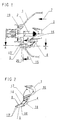
Figur 1- einen mittleren vertikalen Längsschnitt durch einen Reflektor eines Scheinwerfers für Fahrzeuge mit einer einer Lichtquelle zugeordneten Blende,
Figur 2- eine perspektivische Ansicht der Blende aus
Figur 1 als Einzelteil, Figur 3- eine Schnittansicht nach der Linie A-A in
Figur 1, Figur 4- eine Schnittansicht in vergrößertem Maßstab nach der Linie B-B in
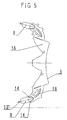
Figur 1 und Figur 5- eine Abwicklung der Blende nach
Figur 2.
- Figure 1
- FIG. 2 shows a middle vertical longitudinal section through a reflector of a headlight for vehicles with an aperture assigned to a light source,
- Figure 2
- 2 shows a perspective view of the diaphragm from FIG. 1 as a single part,
- Figure 3
- 2 shows a sectional view along the line AA in FIG. 1,
- Figure 4
- a sectional view on an enlarged scale along the line BB in Figure 1 and
- Figure 5
- a development of the panel according to Figure 2.
Der in der Zeichnung dargestellte Scheinwerfer weist einen aus Kunststoff bestehenden
schalenförmigen Reflektor 1 mit einer im Scheitelbereich des Reflektors
1 eingebrachten Öffnung zur Aufnahme einer Lichtquelle 2 auf. Die Lichtquelle
2 kann von einer Glühlampe oder einer Gasentladungslampe gebildet
sein. In Lichtaustrittsrichtung ist nach der Lichtquelle 2 eine Blende 3 angeordnet,
welche direkt aus der Lichtquelle 2 austretende und sonst den Gegenverkehr
blendende Lichtstrahlen abschirmt. Die Blende 3 weist einen zur optischen
Achse des Reflektors 1 konzentrisch verlaufenden ringförmigen Blendenabschnitt
16 auf. Der ringförmige Blendenabschnitt 16 weist im unteren Bereich
eine Nahtstelle 17 auf, von der sich ausgehend ein aus zwei plattenförmigen
Blechabschnitten 18 gedoppelter Tragarm 4 nach unten erstreckt. Der freie
Endabschnitt 5 des Tragarms 4 geht in die plattenförmigen Blechabschnitte 18
über und ist von zwei Halbschalen 8 gebildet, die einen sich zum freien Ende
des Tragarms 4 sich verjüngenden Konus bilden. Der konische Endabschnitt 5
verläuft in seiner Längsausdehnung parallel zur optischen Achse des Reflektors
1 und ist in Einsetzrichtung 7 in eine dem konischen Endabschnitt 5 entsprechend
ausgeführte konische Reflektoröffnung 6 eines Hohlzylinders 20 des
Reflektors 1 eingeführt. Der Hohlzylinder 20 ragt sowohl von der Reflektorvorderseite
als auch Reflektorrückseite ab. Die den Endabschnitt 5 bildenden
Halbschalen 8 erstrecken sich bis auf die plattenförmigen Blechabschnitte 18
und verjüngen sich im Bereich der Blechabschnitte 18 entgegen der Einsetzrichtung
7. Die beiden Halbschalen 8 grenzen an einer oberen und unteren
Nahtstelle 9 bzw. 10 aneinander. An der Nahstelle 9 liegen radial nach innen
gerichtete bogenförmige Randabschnitte 12 mit ihrem freien Rand aneinander,
wobei die Stirnflächen der Randabschnitte 12 in einer Fläche verlaufen. Die
andere Nahtstelle 10 verläuft mittig durch eine Abflachung 11 des Endabschnitts,
welche an eine entsprechend große Abflachung der Innenseite der
Reflektoröffnung 6 anliegt. Die plattenförmigen Blechabschnitte 18 weisen auf
sich abgewandten Seiten des Endabschnitts 5 jeweils eine in Einsetzrichtung
gerichtet Anlagefläche 14 auf, die nach dem Einführen an eine von einer Stirnfläche
des Hohlzylinders gebildete Anschlagfläche 15 anschlägt. Danach liegt
der Endabschnitt 5 unter Vorspannung an der Innenfläche der Reflektoröffnung
6 an und sitzt selbstklemmend fest. Der Endabschnitt 5 liegt immer mit einer
großen Klemmkraft an der Innfläche der Reflektoröffnung 6 an, da der Endabschnitt
wegen den nach innen gebogenen Randabschnitten 12 radial federnd
nachgiebig ist. Der Endabschnitt 5 ragt mit seinem freien Ende 13 auf der
Rückseite des Reflektors 1 aus der Reflektoröffnung 6 heraus. Das freie Ende
13 ist von zwei sich gegenüberliegenden Lappen gebildet, die in entgegensetzte
Richtung zum Randbereich der Reflektoröffnung 6 hin gebogen sind, an dem
Randbereich unter Vorspannung anliegen und den Festsitz des Endabschnitts
5 in der Reflektoröffnung 6 sichern. In Figur 3 sind mit 13' die freien Enden 13
vor dem Abwinkeln dargestellt. The headlight shown in the drawing has an existing plastic
bowl-
- 11
- Reflektorreflector
- 22
- Lichtquellelight source
- 33
- Blendecover
- 44
- TragarmBeam
- 55
- Endabschnittend
- 66
- Reflektoröffnungreflector opening
- 77
- Einsetzrichtunginsertion
- 88th
- Halbschalenshells
- 99
- Nahtstellenseams
- 1010
- Nahtstellenseams
- 1111
- Abflachungflattening
- 1212
- Randabschnitteedge sections
- 1313
- Freies EndeFree end
- 1414
- Anlageflächecontact surface
- 1515
- Anschlagflächestop surface
- 1616
- Ringförmiger BlechabschnittAnnular sheet metal section
- 1717
- Nahtstellejoin
- 1818
- Plattenförmiger BlechabschnittPlate-shaped sheet section
- 1919
- Öffnungopening
- 2020
- Hohlzylinderhollow cylinder
Claims (10)
Applications Claiming Priority (2)
| Application Number | Priority Date | Filing Date | Title |
|---|---|---|---|
| DE10120216A DE10120216A1 (en) | 2001-04-25 | 2001-04-25 | Headlights for vehicles |
| DE10120216 | 2001-04-25 |
Publications (3)
| Publication Number | Publication Date |
|---|---|
| EP1253374A2 true EP1253374A2 (en) | 2002-10-30 |
| EP1253374A3 EP1253374A3 (en) | 2005-06-01 |
| EP1253374B1 EP1253374B1 (en) | 2007-02-07 |
Family
ID=7682643
Family Applications (1)
| Application Number | Title | Priority Date | Filing Date |
|---|---|---|---|
| EP02008550A Expired - Lifetime EP1253374B1 (en) | 2001-04-25 | 2002-04-16 | Vehicle headlamp |
Country Status (4)
| Country | Link |
|---|---|
| EP (1) | EP1253374B1 (en) |
| AT (1) | ATE353421T1 (en) |
| DE (2) | DE10120216A1 (en) |
| ES (1) | ES2281470T3 (en) |
Cited By (2)
| Publication number | Priority date | Publication date | Assignee | Title |
|---|---|---|---|---|
| EP1564483A2 (en) * | 2004-02-13 | 2005-08-17 | Valeo Sylvania L.L.C. | Light shield mounting for automotive headlamp |
| EP1813860A1 (en) * | 2006-01-31 | 2007-08-01 | Valeo Vision | Occultation element for the reflector of a projector and method for mounting such an element |
Citations (2)
| Publication number | Priority date | Publication date | Assignee | Title |
|---|---|---|---|---|
| EP0636821B1 (en) | 1993-07-26 | 2000-03-22 | Dynamic Air Inc. | Shaft seal for butterfly valve |
| DE19944254A1 (en) | 1998-09-16 | 2000-04-06 | Koito Mfg Co Ltd | Vehicle lamp for preventing exposure to damage for a car lamp, uses a lamp chamber fitted with a cantilevered light shielding shade, fitted with an extendable leg, which secures and braces the lamp |
Family Cites Families (4)
| Publication number | Priority date | Publication date | Assignee | Title |
|---|---|---|---|---|
| DE4325142C1 (en) * | 1993-07-27 | 1994-07-21 | Hella Kg Hueck & Co | Beam dipping device for vehicle headlamp unit |
| DE19739114A1 (en) * | 1997-09-06 | 1999-03-11 | Hella Kg Hueck & Co | Headlights for vehicles |
| FR2783037B1 (en) * | 1998-09-04 | 2000-12-29 | Valeo Vision | METHOD OF MOUNTING AN OCCULTER IN A MOTOR VEHICLE PROJECTOR, AND PROJECTOR PROVIDED WITH CORRESPONDING MOUNTING MEANS |
| DE29824174U1 (en) * | 1998-10-09 | 2000-06-08 | Hella Kg Hueck & Co | Headlights for vehicles |
-
2001
- 2001-04-25 DE DE10120216A patent/DE10120216A1/en not_active Withdrawn
-
2002
- 2002-04-16 ES ES02008550T patent/ES2281470T3/en not_active Expired - Lifetime
- 2002-04-16 AT AT02008550T patent/ATE353421T1/en not_active IP Right Cessation
- 2002-04-16 DE DE50209421T patent/DE50209421D1/en not_active Expired - Lifetime
- 2002-04-16 EP EP02008550A patent/EP1253374B1/en not_active Expired - Lifetime
Patent Citations (2)
| Publication number | Priority date | Publication date | Assignee | Title |
|---|---|---|---|---|
| EP0636821B1 (en) | 1993-07-26 | 2000-03-22 | Dynamic Air Inc. | Shaft seal for butterfly valve |
| DE19944254A1 (en) | 1998-09-16 | 2000-04-06 | Koito Mfg Co Ltd | Vehicle lamp for preventing exposure to damage for a car lamp, uses a lamp chamber fitted with a cantilevered light shielding shade, fitted with an extendable leg, which secures and braces the lamp |
Cited By (4)
| Publication number | Priority date | Publication date | Assignee | Title |
|---|---|---|---|---|
| EP1564483A2 (en) * | 2004-02-13 | 2005-08-17 | Valeo Sylvania L.L.C. | Light shield mounting for automotive headlamp |
| EP1564483A3 (en) * | 2004-02-13 | 2006-12-06 | Valeo Sylvania L.L.C. | Light shield mounting for automotive headlamp |
| EP1813860A1 (en) * | 2006-01-31 | 2007-08-01 | Valeo Vision | Occultation element for the reflector of a projector and method for mounting such an element |
| FR2896851A1 (en) * | 2006-01-31 | 2007-08-03 | Valeo Vision Sa | PROJECTOR REFLECTOR OCCULTATION ELEMENT AND METHOD OF MOUNTING SUCH A CULTURING ELEMENT. |
Also Published As
| Publication number | Publication date |
|---|---|
| ATE353421T1 (en) | 2007-02-15 |
| DE50209421D1 (en) | 2007-03-22 |
| DE10120216A1 (en) | 2003-01-02 |
| EP1253374A3 (en) | 2005-06-01 |
| ES2281470T3 (en) | 2007-10-01 |
| EP1253374B1 (en) | 2007-02-07 |
Similar Documents
| Publication | Publication Date | Title |
|---|---|---|
| DE102010017275B4 (en) | Side lighting projection lens and front headlamp with same | |
| EP0355528B1 (en) | Dipped vehicle headlamp | |
| DE19846797A1 (en) | Headlamp for automobile | |
| DE4229728C1 (en) | Dual-reflector headlamp assembly for vehicle - has cut=outs in edge of dipped beam reflector to illuminate driving beam reflector | |
| DE19908641A1 (en) | Headlights for vehicles | |
| DE19905115B4 (en) | Headlights for vehicles | |
| DE19602978B4 (en) | Vehicle headlights | |
| EP1762774B1 (en) | Headlamp | |
| DE19750494B4 (en) | Method of making high beam headlamps for vehicles | |
| EP1253374B1 (en) | Vehicle headlamp | |
| DE60131600T3 (en) | Elliptical spotlight for street lighting with improved low-photometry | |
| DE4133527C2 (en) | Headlights for motor vehicles | |
| EP0422084B1 (en) | Light, in particular a light for motor vehicles | |
| DD232337A5 (en) | Dazzled VEHICLE HEADLAMP | |
| DE19916174B4 (en) | Optical element of a cover of a motor vehicle headlight | |
| DE10004701A1 (en) | Headlights for vehicles according to the projection principle | |
| DE19947876B4 (en) | Headlights for vehicles | |
| DE19750495B4 (en) | Headlamp system for vehicles | |
| EP0985871A2 (en) | Headlamp and method of making the same | |
| DE19758003B4 (en) | Sheet metal abutment for mounting on a support and method of manufacture | |
| EP0636831B1 (en) | Screen for a non-dazzling headlamp of a motor vehicle | |
| DD284079A5 (en) | DEFLECTED VEHICLE HEADLAMP ACCORDING TO THE PROJECTION PRINCIPLE | |
| DE102004011090B4 (en) | Headlights for vehicles | |
| DE3742191C2 (en) | ||
| DE10258535B4 (en) | Vehicle headlight with a beam stop |
Legal Events
| Date | Code | Title | Description |
|---|---|---|---|
| PUAI | Public reference made under article 153(3) epc to a published international application that has entered the european phase |
Free format text: ORIGINAL CODE: 0009012 |
|
| AK | Designated contracting states |
Kind code of ref document: A2 Designated state(s): AT BE CH CY DE DK ES FI FR GB GR IE IT LI LU MC NL PT SE TR |
|
| AX | Request for extension of the european patent |
Free format text: AL;LT;LV;MK;RO;SI |
|
| RAP1 | Party data changed (applicant data changed or rights of an application transferred) |
Owner name: HELLA KGAA HUECK & CO. |
|
| PUAL | Search report despatched |
Free format text: ORIGINAL CODE: 0009013 |
|
| AK | Designated contracting states |
Kind code of ref document: A3 Designated state(s): AT BE CH CY DE DK ES FI FR GB GR IE IT LI LU MC NL PT SE TR |
|
| AX | Request for extension of the european patent |
Extension state: AL LT LV MK RO SI |
|
| RIC1 | Information provided on ipc code assigned before grant |
Ipc: 7F 21V 11/16 A Ipc: 7F 21W 101:10 Z Ipc: 7F 21V 17/00 B |
|
| 17P | Request for examination filed |
Effective date: 20051128 |
|
| GRAP | Despatch of communication of intention to grant a patent |
Free format text: ORIGINAL CODE: EPIDOSNIGR1 |
|
| AKX | Designation fees paid |
Designated state(s): AT DE ES FR GB IT |
|
| GRAS | Grant fee paid |
Free format text: ORIGINAL CODE: EPIDOSNIGR3 |
|
| GRAA | (expected) grant |
Free format text: ORIGINAL CODE: 0009210 |
|
| AK | Designated contracting states |
Kind code of ref document: B1 Designated state(s): AT DE ES FR IT |
|
| RBV | Designated contracting states (corrected) |
Designated state(s): AT DE ES FR IT |
|
| REF | Corresponds to: |
Ref document number: 50209421 Country of ref document: DE Date of ref document: 20070322 Kind code of ref document: P |
|
| PGFP | Annual fee paid to national office [announced via postgrant information from national office to epo] |
Ref country code: AT Payment date: 20070412 Year of fee payment: 6 |
|
| PGFP | Annual fee paid to national office [announced via postgrant information from national office to epo] |
Ref country code: ES Payment date: 20070521 Year of fee payment: 6 |
|
| ET | Fr: translation filed | ||
| REG | Reference to a national code |
Ref country code: ES Ref legal event code: FG2A Ref document number: 2281470 Country of ref document: ES Kind code of ref document: T3 |
|
| PLBE | No opposition filed within time limit |
Free format text: ORIGINAL CODE: 0009261 |
|
| STAA | Information on the status of an ep patent application or granted ep patent |
Free format text: STATUS: NO OPPOSITION FILED WITHIN TIME LIMIT |
|
| PGFP | Annual fee paid to national office [announced via postgrant information from national office to epo] |
Ref country code: IT Payment date: 20070511 Year of fee payment: 6 |
|
| 26N | No opposition filed |
Effective date: 20071108 |
|
| PG25 | Lapsed in a contracting state [announced via postgrant information from national office to epo] |
Ref country code: AT Free format text: LAPSE BECAUSE OF NON-PAYMENT OF DUE FEES Effective date: 20080416 |
|
| REG | Reference to a national code |
Ref country code: ES Ref legal event code: FD2A Effective date: 20080417 |
|
| PG25 | Lapsed in a contracting state [announced via postgrant information from national office to epo] |
Ref country code: ES Free format text: LAPSE BECAUSE OF NON-PAYMENT OF DUE FEES Effective date: 20080417 |
|
| PG25 | Lapsed in a contracting state [announced via postgrant information from national office to epo] |
Ref country code: IT Free format text: LAPSE BECAUSE OF NON-PAYMENT OF DUE FEES Effective date: 20080416 |
|
| PGFP | Annual fee paid to national office [announced via postgrant information from national office to epo] |
Ref country code: FR Payment date: 20130625 Year of fee payment: 12 |
|
| REG | Reference to a national code |
Ref country code: FR Ref legal event code: ST Effective date: 20141231 |
|
| PG25 | Lapsed in a contracting state [announced via postgrant information from national office to epo] |
Ref country code: FR Free format text: LAPSE BECAUSE OF NON-PAYMENT OF DUE FEES Effective date: 20140430 |
|
| REG | Reference to a national code |
Ref country code: DE Ref legal event code: R081 Ref document number: 50209421 Country of ref document: DE Owner name: HELLA GMBH & CO. KGAA, DE Free format text: FORMER OWNER: HELLA KG HUECK & CO., 59557 LIPPSTADT, DE |
|
| REG | Reference to a national code |
Ref country code: DE Ref legal event code: R084 Ref document number: 50209421 Country of ref document: DE |
|
| PGFP | Annual fee paid to national office [announced via postgrant information from national office to epo] |
Ref country code: DE Payment date: 20190402 Year of fee payment: 18 |
|
| REG | Reference to a national code |
Ref country code: DE Ref legal event code: R119 Ref document number: 50209421 Country of ref document: DE |
|
| PG25 | Lapsed in a contracting state [announced via postgrant information from national office to epo] |
Ref country code: DE Free format text: LAPSE BECAUSE OF NON-PAYMENT OF DUE FEES Effective date: 20201103 |