EP1564483A2 - Light shield mounting for automotive headlamp - Google Patents
Light shield mounting for automotive headlamp Download PDFInfo
- Publication number
- EP1564483A2 EP1564483A2 EP05002874A EP05002874A EP1564483A2 EP 1564483 A2 EP1564483 A2 EP 1564483A2 EP 05002874 A EP05002874 A EP 05002874A EP 05002874 A EP05002874 A EP 05002874A EP 1564483 A2 EP1564483 A2 EP 1564483A2
- Authority
- EP
- European Patent Office
- Prior art keywords
- nibs
- reflector
- inverted
- shield
- shaped aperture
- Prior art date
- Legal status (The legal status is an assumption and is not a legal conclusion. Google has not performed a legal analysis and makes no representation as to the accuracy of the status listed.)
- Granted
Links
- 230000000149 penetrating effect Effects 0.000 claims abstract description 3
- 230000013011 mating Effects 0.000 claims description 2
- 230000035515 penetration Effects 0.000 claims description 2
- 230000004048 modification Effects 0.000 description 1
- 238000012986 modification Methods 0.000 description 1
- 229920006305 unsaturated polyester Polymers 0.000 description 1
Images


Classifications
-
- F—MECHANICAL ENGINEERING; LIGHTING; HEATING; WEAPONS; BLASTING
- F21—LIGHTING
- F21S—NON-PORTABLE LIGHTING DEVICES; SYSTEMS THEREOF; VEHICLE LIGHTING DEVICES SPECIALLY ADAPTED FOR VEHICLE EXTERIORS
- F21S41/00—Illuminating devices specially adapted for vehicle exteriors, e.g. headlamps
- F21S41/40—Illuminating devices specially adapted for vehicle exteriors, e.g. headlamps characterised by screens, non-reflecting members, light-shielding members or fixed shades
- F21S41/43—Illuminating devices specially adapted for vehicle exteriors, e.g. headlamps characterised by screens, non-reflecting members, light-shielding members or fixed shades characterised by the shape thereof
- F21S41/435—Hoods or cap-shaped
-
- F—MECHANICAL ENGINEERING; LIGHTING; HEATING; WEAPONS; BLASTING
- F21—LIGHTING
- F21S—NON-PORTABLE LIGHTING DEVICES; SYSTEMS THEREOF; VEHICLE LIGHTING DEVICES SPECIALLY ADAPTED FOR VEHICLE EXTERIORS
- F21S41/00—Illuminating devices specially adapted for vehicle exteriors, e.g. headlamps
- F21S41/40—Illuminating devices specially adapted for vehicle exteriors, e.g. headlamps characterised by screens, non-reflecting members, light-shielding members or fixed shades
- F21S41/47—Attachment thereof
Definitions
- This invention relates to lamp units and more particularly to automotive headlamps. Still more particularly it relates to a reflector and shield for an automotive headlamp unit.
- Automotive headlamps employ small light sources arranged in a reflector. It is common practice to cover the forwardmost facing part of the light source with a cup-shaped shield. Mounting the shield is a continuing problem usually solved by having an arm on the shield having a distal end that is fixed to the reflector at a remote location, usually by a screw or by a pressed-in fit. Use of the screw introduces an extra part raising the cost while the pressed-in feature allows the shield to fall out if it is not properly engaged.
- a lamp unit comprising: a reflector having a reflector surface with an inverted U-shaped aperture formed therein and extending through said reflector to an opposite surface, said inverted U-shaped aperture thereby having the bight uppermost with a pair of channels depending therefrom; and a light-shield comprising a cup-shaped member having an arm projecting therefrom, said arm having a distal end formed to provide a pair of nibs for engaging and penetrating said channels of said inverted U-shaped aperture and having their ends deformed to fix the position of said light-shield relative to said reflector.
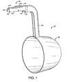
- FIG. 1 is a perspective view of a shield in accordance with an aspect of the invention.
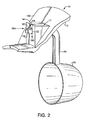
- Fig. 2 is a perspective view of a shield first mounted to a reflector
- Fig. 3 is a perspective view of the front or reflector surface side of an aperture formed in the reflector
- Fig. 4 is a perspective view of the rear surface of the aperture formed in the reflector
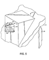
- FIG. 5 is a perspective view of a first embodiment of deformation of the shield fixing means
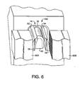
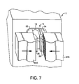
- FIGs. 6 and 7 are diagrammatic perspective views of the sequence of operation for accomplishing the deformation of the first embodiment
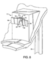
- FIG. 8 is perspective view of a second embodiment of the deformation of the shield fixing means
- Fig. 9 is a diagrammatic plan view of the sequence of operation for accomplishing the deformation of the second embodiment.
- Fig. 10 is a perspective view, partially in section, of a spring element used for positioning the shield.
- a light-shield 24 having a cup-shaped member 26 with an arm 28 projecting therefrom.
- the arm 28 has a distal end 30 formed to provide nibs 32, 34 having ends 36, 38.
- a reflector 10 (see particularly Figs. 2, 3, and 4) has a reflector surface 12 with an inverted U-shaped aperture 14 formed therein and extending through the reflector to an opposite surface 16.
- a housing 17 is formed with surface 16.
- the inverted U-shaped aperture 14 has a bight 18 uppermost and channels 20, 22 depending therefrom to receive the nibs 32, 34, as shown in Fig. 2.
- Aperture 14 has an entrance side 12a and an exit side 16a and the entrance side 12a is provided with a stop 40 that limits the penetration of nibs 32 and 34 into the aperture 14.
- the stop 40 cooperates with mating stop edges 42, 43 formed on nibs 32, 34.
- a transverse web 44 connects the nibs 32, 34 for a part of their length and is provided with a tensioning spring member 46. As shown in Fig. 10, when the nibs 32, 34 are inserted into the channels 20, 22, the tensioning spring 46 exerts pressure against the bight 18 and the rib 48 formed between the channels 20, 22, thereby accurately positioning the light-shield 24 with respect to the reflector 10.
- Figs. 6 and 7 illustrate the inward deformation performed by tools 60a and 60b while Fig. 9 illustrates the outward deformation performed by a tool 62.
- the reflector material is unsaturated polyester and the light-shield material is 1008 - 1010 C.R.S.
Landscapes
- Engineering & Computer Science (AREA)
- General Engineering & Computer Science (AREA)
- Non-Portable Lighting Devices Or Systems Thereof (AREA)
- Lighting Device Outwards From Vehicle And Optical Signal (AREA)
- Securing Globes, Refractors, Reflectors Or The Like (AREA)
Abstract
Description
Claims (5)
- A lamp unit comprising:a reflector having a reflector surface with an inverted U-shaped aperture formed therein and extending through said reflector to an opposite surface, said inverted U-shaped aperture thereby having the bight uppermost with a pair of channels depending therefrom; anda light-shield comprising a cup-shaped member having an arm projecting therefrom, said arm having a distal end formed to provide a pair of nibs for engaging and penetrating said channels of said inverted U-shaped aperture and having their ends deformed to fix the position of said light-shield relative to said reflector.
- The lamp unit of Claim 1 wherein said nibs have their ends deformed outwardly.
- The lamp unit of Claim 1 wherein said nibs have their ends deformed inwardly.
- The lamp unit of Claim 1 wherein said inverted U-shaped aperture has an entrance side and an exit side and said entrance side is provided with a stop that cooperates with mating stop edges formed in said nibs and determines the degree of penetration of said nibs into said channels of said inverted U-shaped aperture.
- The lamp unit of Claim 1 wherein said nibs have a transverse bar connecting them for part of their length and said transverse bar is provided with a tensioning spring.
Applications Claiming Priority (2)
| Application Number | Priority Date | Filing Date | Title |
|---|---|---|---|
| US778775 | 2004-02-13 | ||
| US10/778,775 US7011437B2 (en) | 2004-02-13 | 2004-02-13 | Light shield mounting for automotive headlamp |
Publications (3)
| Publication Number | Publication Date |
|---|---|
| EP1564483A2 true EP1564483A2 (en) | 2005-08-17 |
| EP1564483A3 EP1564483A3 (en) | 2006-12-06 |
| EP1564483B1 EP1564483B1 (en) | 2008-11-12 |
Family
ID=34701401
Family Applications (1)
| Application Number | Title | Priority Date | Filing Date |
|---|---|---|---|
| EP20050002874 Expired - Lifetime EP1564483B1 (en) | 2004-02-13 | 2005-02-11 | Light shield mounting for automotive headlamp |
Country Status (4)
| Country | Link |
|---|---|
| US (1) | US7011437B2 (en) |
| EP (1) | EP1564483B1 (en) |
| AT (1) | ATE414240T1 (en) |
| DE (1) | DE602005010922D1 (en) |
Cited By (2)
| Publication number | Priority date | Publication date | Assignee | Title |
|---|---|---|---|---|
| EP1574781A3 (en) * | 2004-03-08 | 2006-12-06 | Valeo Sylvania L.L.C. | Light shield mounting for automotive headlamp |
| EP2157368A1 (en) * | 2008-08-21 | 2010-02-24 | Peugeot Citroën Automobiles Société Anonyme | Optical unit for automotive vehicle, with screen suspended to the lamp housing |
Families Citing this family (1)
| Publication number | Priority date | Publication date | Assignee | Title |
|---|---|---|---|---|
| JP4658723B2 (en) * | 2005-07-14 | 2011-03-23 | 株式会社小森コーポレーション | Printing machine or coating machine |
Family Cites Families (4)
| Publication number | Priority date | Publication date | Assignee | Title |
|---|---|---|---|---|
| JP3810927B2 (en) * | 1998-09-16 | 2006-08-16 | 株式会社小糸製作所 | Vehicle lighting |
| JP3655560B2 (en) * | 2001-04-24 | 2005-06-02 | 株式会社小糸製作所 | Infrared irradiation lamp for automobiles |
| DE10120216A1 (en) * | 2001-04-25 | 2003-01-02 | Hella Kg Hueck & Co | Headlights for vehicles |
| US7008098B2 (en) * | 2001-05-14 | 2006-03-07 | Denso Corporation | Vehicle headlamp assembly with lampshade and lighting circuit separately mounted to reflector |
-
2004
- 2004-02-13 US US10/778,775 patent/US7011437B2/en not_active Expired - Lifetime
-
2005
- 2005-02-11 EP EP20050002874 patent/EP1564483B1/en not_active Expired - Lifetime
- 2005-02-11 AT AT05002874T patent/ATE414240T1/en not_active IP Right Cessation
- 2005-02-11 DE DE200560010922 patent/DE602005010922D1/en not_active Expired - Lifetime
Cited By (2)
| Publication number | Priority date | Publication date | Assignee | Title |
|---|---|---|---|---|
| EP1574781A3 (en) * | 2004-03-08 | 2006-12-06 | Valeo Sylvania L.L.C. | Light shield mounting for automotive headlamp |
| EP2157368A1 (en) * | 2008-08-21 | 2010-02-24 | Peugeot Citroën Automobiles Société Anonyme | Optical unit for automotive vehicle, with screen suspended to the lamp housing |
Also Published As
| Publication number | Publication date |
|---|---|
| ATE414240T1 (en) | 2008-11-15 |
| US20050180143A1 (en) | 2005-08-18 |
| EP1564483A3 (en) | 2006-12-06 |
| DE602005010922D1 (en) | 2008-12-24 |
| US7011437B2 (en) | 2006-03-14 |
| EP1564483B1 (en) | 2008-11-12 |
Similar Documents
| Publication | Publication Date | Title |
|---|---|---|
| JP5906050B2 (en) | Vehicle lighting | |
| EP0089179A2 (en) | Integrated light unit and circuit element attachable to circuit board | |
| JP2002276633A (en) | Resin clip | |
| US20110051450A1 (en) | Positioning structure of turn lamp assembly in outer mirror with turn lamp | |
| US7011437B2 (en) | Light shield mounting for automotive headlamp | |
| CN210511493U (en) | Optical assembly and vehicle lamp for vehicle | |
| JP7270394B2 (en) | Light source unit and lighting equipment | |
| US20140334184A1 (en) | Bulb socket and lighting system | |
| US5605392A (en) | Headlight-light unit for vehicle | |
| US7014346B2 (en) | Light shield mounting for automotive headlamp | |
| ES2201233T3 (en) | DEVICE FOR FIXING A PILOT OR A LIGHTHOUSE. | |
| JP6068087B2 (en) | Design part fixing structure and vehicle lamp | |
| EP4509363B1 (en) | Clamping means for a light guide element and light guide element arrangement with such a clamping means | |
| JP7420634B2 (en) | Vehicle lights | |
| US6926433B2 (en) | Push-in light shield | |
| EP1452799B1 (en) | Push-in light shield | |
| JP2000156105A (en) | Vehicle lighting | |
| KR200427432Y1 (en) | Lamp holder assembly | |
| JP2000215727A (en) | lighting equipment | |
| JP2003168319A (en) | Lighting fixture with wall | |
| ATE181291T1 (en) | HOLDING DEVICE FOR AN ADJUSTABLE REFLECTOR OF A VEHICLE HEADLIGHT | |
| GB2414272A (en) | Holder for a cable lock | |
| US20060256567A1 (en) | Structure for lighting unit | |
| JP2001063459A (en) | Vehicle lighting | |
| JPH10321014A (en) | Vehicle lighting |
Legal Events
| Date | Code | Title | Description |
|---|---|---|---|
| PUAI | Public reference made under article 153(3) epc to a published international application that has entered the european phase |
Free format text: ORIGINAL CODE: 0009012 |
|
| AK | Designated contracting states |
Kind code of ref document: A2 Designated state(s): AT BE BG CH CY CZ DE DK EE ES FI FR GB GR HU IE IS IT LI LT LU MC NL PL PT RO SE SI SK TR |
|
| AX | Request for extension of the european patent |
Extension state: AL BA HR LV MK YU |
|
| PUAL | Search report despatched |
Free format text: ORIGINAL CODE: 0009013 |
|
| AK | Designated contracting states |
Kind code of ref document: A3 Designated state(s): AT BE BG CH CY CZ DE DK EE ES FI FR GB GR HU IE IS IT LI LT LU MC NL PL PT RO SE SI SK TR |
|
| AX | Request for extension of the european patent |
Extension state: AL BA HR LV MK YU |
|
| 17P | Request for examination filed |
Effective date: 20070524 |
|
| AKX | Designation fees paid |
Designated state(s): AT BE BG CH CY CZ DE DK EE ES FI FR GB GR HU IE IS IT LI LT LU MC NL PL PT RO SE SI SK TR |
|
| 17Q | First examination report despatched |
Effective date: 20070828 |
|
| GRAP | Despatch of communication of intention to grant a patent |
Free format text: ORIGINAL CODE: EPIDOSNIGR1 |
|
| RAP1 | Party data changed (applicant data changed or rights of an application transferred) |
Owner name: VALEO SYLVANIA L.L.C. |
|
| GRAS | Grant fee paid |
Free format text: ORIGINAL CODE: EPIDOSNIGR3 |
|
| GRAA | (expected) grant |
Free format text: ORIGINAL CODE: 0009210 |
|
| AK | Designated contracting states |
Kind code of ref document: B1 Designated state(s): AT BE BG CH CY CZ DE DK EE ES FI FR GB GR HU IE IS IT LI LT LU MC NL PL PT RO SE SI SK TR |
|
| REG | Reference to a national code |
Ref country code: GB Ref legal event code: FG4D |
|
| REG | Reference to a national code |
Ref country code: CH Ref legal event code: EP |
|
| REG | Reference to a national code |
Ref country code: IE Ref legal event code: FG4D |
|
| REF | Corresponds to: |
Ref document number: 602005010922 Country of ref document: DE Date of ref document: 20081224 Kind code of ref document: P |
|
| LTIE | Lt: invalidation of european patent or patent extension |
Effective date: 20081112 |
|
| PG25 | Lapsed in a contracting state [announced via postgrant information from national office to epo] |
Ref country code: ES Free format text: LAPSE BECAUSE OF FAILURE TO SUBMIT A TRANSLATION OF THE DESCRIPTION OR TO PAY THE FEE WITHIN THE PRESCRIBED TIME-LIMIT Effective date: 20090223 Ref country code: LT Free format text: LAPSE BECAUSE OF FAILURE TO SUBMIT A TRANSLATION OF THE DESCRIPTION OR TO PAY THE FEE WITHIN THE PRESCRIBED TIME-LIMIT Effective date: 20081112 Ref country code: AT Free format text: LAPSE BECAUSE OF FAILURE TO SUBMIT A TRANSLATION OF THE DESCRIPTION OR TO PAY THE FEE WITHIN THE PRESCRIBED TIME-LIMIT Effective date: 20081112 |
|
| NLV1 | Nl: lapsed or annulled due to failure to fulfill the requirements of art. 29p and 29m of the patents act | ||
| PG25 | Lapsed in a contracting state [announced via postgrant information from national office to epo] |
Ref country code: SI Free format text: LAPSE BECAUSE OF FAILURE TO SUBMIT A TRANSLATION OF THE DESCRIPTION OR TO PAY THE FEE WITHIN THE PRESCRIBED TIME-LIMIT Effective date: 20081112 Ref country code: PL Free format text: LAPSE BECAUSE OF FAILURE TO SUBMIT A TRANSLATION OF THE DESCRIPTION OR TO PAY THE FEE WITHIN THE PRESCRIBED TIME-LIMIT Effective date: 20081112 Ref country code: NL Free format text: LAPSE BECAUSE OF FAILURE TO SUBMIT A TRANSLATION OF THE DESCRIPTION OR TO PAY THE FEE WITHIN THE PRESCRIBED TIME-LIMIT Effective date: 20081112 Ref country code: FI Free format text: LAPSE BECAUSE OF FAILURE TO SUBMIT A TRANSLATION OF THE DESCRIPTION OR TO PAY THE FEE WITHIN THE PRESCRIBED TIME-LIMIT Effective date: 20081112 Ref country code: IS Free format text: LAPSE BECAUSE OF FAILURE TO SUBMIT A TRANSLATION OF THE DESCRIPTION OR TO PAY THE FEE WITHIN THE PRESCRIBED TIME-LIMIT Effective date: 20090312 |
|
| PG25 | Lapsed in a contracting state [announced via postgrant information from national office to epo] |
Ref country code: BG Free format text: LAPSE BECAUSE OF FAILURE TO SUBMIT A TRANSLATION OF THE DESCRIPTION OR TO PAY THE FEE WITHIN THE PRESCRIBED TIME-LIMIT Effective date: 20090212 Ref country code: RO Free format text: LAPSE BECAUSE OF FAILURE TO SUBMIT A TRANSLATION OF THE DESCRIPTION OR TO PAY THE FEE WITHIN THE PRESCRIBED TIME-LIMIT Effective date: 20081112 Ref country code: EE Free format text: LAPSE BECAUSE OF FAILURE TO SUBMIT A TRANSLATION OF THE DESCRIPTION OR TO PAY THE FEE WITHIN THE PRESCRIBED TIME-LIMIT Effective date: 20081112 Ref country code: DK Free format text: LAPSE BECAUSE OF FAILURE TO SUBMIT A TRANSLATION OF THE DESCRIPTION OR TO PAY THE FEE WITHIN THE PRESCRIBED TIME-LIMIT Effective date: 20081112 Ref country code: BE Free format text: LAPSE BECAUSE OF FAILURE TO SUBMIT A TRANSLATION OF THE DESCRIPTION OR TO PAY THE FEE WITHIN THE PRESCRIBED TIME-LIMIT Effective date: 20081112 |
|
| PG25 | Lapsed in a contracting state [announced via postgrant information from national office to epo] |
Ref country code: PT Free format text: LAPSE BECAUSE OF FAILURE TO SUBMIT A TRANSLATION OF THE DESCRIPTION OR TO PAY THE FEE WITHIN THE PRESCRIBED TIME-LIMIT Effective date: 20090413 Ref country code: SE Free format text: LAPSE BECAUSE OF FAILURE TO SUBMIT A TRANSLATION OF THE DESCRIPTION OR TO PAY THE FEE WITHIN THE PRESCRIBED TIME-LIMIT Effective date: 20090212 Ref country code: CZ Free format text: LAPSE BECAUSE OF FAILURE TO SUBMIT A TRANSLATION OF THE DESCRIPTION OR TO PAY THE FEE WITHIN THE PRESCRIBED TIME-LIMIT Effective date: 20081112 |
|
| PLBE | No opposition filed within time limit |
Free format text: ORIGINAL CODE: 0009261 |
|
| STAA | Information on the status of an ep patent application or granted ep patent |
Free format text: STATUS: NO OPPOSITION FILED WITHIN TIME LIMIT |
|
| PG25 | Lapsed in a contracting state [announced via postgrant information from national office to epo] |
Ref country code: MC Free format text: LAPSE BECAUSE OF NON-PAYMENT OF DUE FEES Effective date: 20090228 Ref country code: SK Free format text: LAPSE BECAUSE OF FAILURE TO SUBMIT A TRANSLATION OF THE DESCRIPTION OR TO PAY THE FEE WITHIN THE PRESCRIBED TIME-LIMIT Effective date: 20081112 |
|
| REG | Reference to a national code |
Ref country code: CH Ref legal event code: PL |
|
| 26N | No opposition filed |
Effective date: 20090813 |
|
| PG25 | Lapsed in a contracting state [announced via postgrant information from national office to epo] |
Ref country code: CH Free format text: LAPSE BECAUSE OF NON-PAYMENT OF DUE FEES Effective date: 20090228 Ref country code: LI Free format text: LAPSE BECAUSE OF NON-PAYMENT OF DUE FEES Effective date: 20090228 |
|
| REG | Reference to a national code |
Ref country code: IE Ref legal event code: MM4A |
|
| PG25 | Lapsed in a contracting state [announced via postgrant information from national office to epo] |
Ref country code: IE Free format text: LAPSE BECAUSE OF NON-PAYMENT OF DUE FEES Effective date: 20090211 |
|
| PG25 | Lapsed in a contracting state [announced via postgrant information from national office to epo] |
Ref country code: GR Free format text: LAPSE BECAUSE OF FAILURE TO SUBMIT A TRANSLATION OF THE DESCRIPTION OR TO PAY THE FEE WITHIN THE PRESCRIBED TIME-LIMIT Effective date: 20090213 |
|
| PG25 | Lapsed in a contracting state [announced via postgrant information from national office to epo] |
Ref country code: IT Free format text: LAPSE BECAUSE OF NON-PAYMENT OF DUE FEES Effective date: 20100211 |
|
| PG25 | Lapsed in a contracting state [announced via postgrant information from national office to epo] |
Ref country code: LU Free format text: LAPSE BECAUSE OF NON-PAYMENT OF DUE FEES Effective date: 20090211 |
|
| PG25 | Lapsed in a contracting state [announced via postgrant information from national office to epo] |
Ref country code: HU Free format text: LAPSE BECAUSE OF FAILURE TO SUBMIT A TRANSLATION OF THE DESCRIPTION OR TO PAY THE FEE WITHIN THE PRESCRIBED TIME-LIMIT Effective date: 20090513 |
|
| PG25 | Lapsed in a contracting state [announced via postgrant information from national office to epo] |
Ref country code: TR Free format text: LAPSE BECAUSE OF FAILURE TO SUBMIT A TRANSLATION OF THE DESCRIPTION OR TO PAY THE FEE WITHIN THE PRESCRIBED TIME-LIMIT Effective date: 20081112 |
|
| PG25 | Lapsed in a contracting state [announced via postgrant information from national office to epo] |
Ref country code: CY Free format text: LAPSE BECAUSE OF FAILURE TO SUBMIT A TRANSLATION OF THE DESCRIPTION OR TO PAY THE FEE WITHIN THE PRESCRIBED TIME-LIMIT Effective date: 20081112 |
|
| REG | Reference to a national code |
Ref country code: FR Ref legal event code: PLFP Year of fee payment: 12 |
|
| REG | Reference to a national code |
Ref country code: FR Ref legal event code: PLFP Year of fee payment: 13 |
|
| REG | Reference to a national code |
Ref country code: DE Ref legal event code: R082 Ref document number: 602005010922 Country of ref document: DE |
|
| REG | Reference to a national code |
Ref country code: FR Ref legal event code: PLFP Year of fee payment: 14 |
|
| PGFP | Annual fee paid to national office [announced via postgrant information from national office to epo] |
Ref country code: IT Payment date: 20200211 Year of fee payment: 16 Ref country code: GB Payment date: 20200219 Year of fee payment: 16 Ref country code: DE Payment date: 20200211 Year of fee payment: 16 |
|
| PGFP | Annual fee paid to national office [announced via postgrant information from national office to epo] |
Ref country code: FR Payment date: 20200228 Year of fee payment: 16 |
|
| REG | Reference to a national code |
Ref country code: DE Ref legal event code: R119 Ref document number: 602005010922 Country of ref document: DE |
|
| GBPC | Gb: european patent ceased through non-payment of renewal fee |
Effective date: 20210211 |
|
| PG25 | Lapsed in a contracting state [announced via postgrant information from national office to epo] |
Ref country code: GB Free format text: LAPSE BECAUSE OF NON-PAYMENT OF DUE FEES Effective date: 20210211 Ref country code: FR Free format text: LAPSE BECAUSE OF NON-PAYMENT OF DUE FEES Effective date: 20210228 Ref country code: DE Free format text: LAPSE BECAUSE OF NON-PAYMENT OF DUE FEES Effective date: 20210901 |
|
| PG25 | Lapsed in a contracting state [announced via postgrant information from national office to epo] |
Ref country code: IT Free format text: LAPSE BECAUSE OF NON-PAYMENT OF DUE FEES Effective date: 20210228 |