EP1253340B1 - Nabe einer Schaltkupplung - Google Patents
Nabe einer Schaltkupplung Download PDFInfo
- Publication number
- EP1253340B1 EP1253340B1 EP02005557A EP02005557A EP1253340B1 EP 1253340 B1 EP1253340 B1 EP 1253340B1 EP 02005557 A EP02005557 A EP 02005557A EP 02005557 A EP02005557 A EP 02005557A EP 1253340 B1 EP1253340 B1 EP 1253340B1
- Authority
- EP
- European Patent Office
- Prior art keywords
- hub
- shaped
- clip
- legs
- support elements
- Prior art date
- Legal status (The legal status is an assumption and is not a legal conclusion. Google has not performed a legal analysis and makes no representation as to the accuracy of the status listed.)
- Expired - Lifetime
Links
- 230000005540 biological transmission Effects 0.000 claims abstract description 7
- 239000002184 metal Substances 0.000 claims description 8
- 229910000831 Steel Inorganic materials 0.000 claims description 4
- 239000010959 steel Substances 0.000 claims description 4
- 230000001360 synchronised effect Effects 0.000 claims description 3
- 230000008878 coupling Effects 0.000 abstract 2
- 238000010168 coupling process Methods 0.000 abstract 2
- 238000005859 coupling reaction Methods 0.000 abstract 2
- 238000004519 manufacturing process Methods 0.000 description 3
- 239000000463 material Substances 0.000 description 2
- 230000001419 dependent effect Effects 0.000 description 1
- 238000000465 moulding Methods 0.000 description 1
Images

Classifications
-
- F—MECHANICAL ENGINEERING; LIGHTING; HEATING; WEAPONS; BLASTING
- F16—ENGINEERING ELEMENTS AND UNITS; GENERAL MEASURES FOR PRODUCING AND MAINTAINING EFFECTIVE FUNCTIONING OF MACHINES OR INSTALLATIONS; THERMAL INSULATION IN GENERAL
- F16D—COUPLINGS FOR TRANSMITTING ROTATION; CLUTCHES; BRAKES
- F16D23/00—Details of mechanically-actuated clutches not specific for one distinct type
- F16D23/02—Arrangements for synchronisation, also for power-operated clutches
- F16D23/04—Arrangements for synchronisation, also for power-operated clutches with an additional friction clutch
-
- F—MECHANICAL ENGINEERING; LIGHTING; HEATING; WEAPONS; BLASTING
- F16—ENGINEERING ELEMENTS AND UNITS; GENERAL MEASURES FOR PRODUCING AND MAINTAINING EFFECTIVE FUNCTIONING OF MACHINES OR INSTALLATIONS; THERMAL INSULATION IN GENERAL
- F16D—COUPLINGS FOR TRANSMITTING ROTATION; CLUTCHES; BRAKES
- F16D23/00—Details of mechanically-actuated clutches not specific for one distinct type
- F16D23/02—Arrangements for synchronisation, also for power-operated clutches
- F16D23/04—Arrangements for synchronisation, also for power-operated clutches with an additional friction clutch
- F16D23/06—Arrangements for synchronisation, also for power-operated clutches with an additional friction clutch and a blocking mechanism preventing the engagement of the main clutch prior to synchronisation
- F16D2023/0637—Details relating to the hub member on which the sliding is arranged
Definitions
- the invention relates to a hub of a clutch, the hub formed from at least one substantially cup-shaped sheet metal part having a molded inner toothing for engagement in a transmission shaft and an outer toothing for engagement of a counter toothing on a shift sleeve on the hub.
- Hubs formed from sheet metal parts are characterized in particular by the economical use of material in their manufacture and by low weight.
- a generic hub is disclosed in DE 19942056. In US 4,131,032 A, such a hub is described, which is used in particular in unsynchronized or synchronized clutches of vehicle transmissions.
- a rotationally symmetrical and cup-shaped formed sheet metal part is provided inside and outside each with a longitudinal direction of the hub aligned teeth.
- the internal gearing is formed on a departing from the bottom of the cup, pointing in the longitudinal direction of the hub and arranged concentrically to the outer toothing collar.
- On the collar sits a disc with a Z-shaped cross-section, which is surrounded by the outer toothing on the outside. The disc is welded to the sheet metal part and increases the strength or rigidity of the hub.
- the width of the hub and the width of the toothing are dependent on the loads on the hub during the transmission of torques when the hub seated on the shaft and a gear wheel are connected to the shift sleeve.
- the width of the hub is also determined by the switching paths of the shift sleeve on the hub.
- the shift sleeve sits from an unswitched middle position in the longitudinal direction to the left and right switchable on the hub. In the middle position, the shift sleeve sits well guided by the width of the teeth and supported tilt-safe on the hub. Moved to the left or right for an optional connection with one of the gear wheels, only a left or right portion of the teeth on the hub carries the shift sleeve. Only this proportion then transmits the torques.
- the object of the invention is therefore to provide a hub with which the aforementioned disadvantages are avoided.
- the hub is provided at least on one end face of the hub with axially projecting and widening on the hub and the support width of the hub to the sliding sleeve supporting elements.
- a hub according to the invention now only has to be made as wide as required by the load-bearing portion of the toothing in the engaged state of the sliding sleeve.
- the shift sleeve sits proportionately on the toothing on one longitudinal side, projects beyond the hub and otherwise supports itself on the support elements.
- the support elements preferably close in the axial direction radially outwardly to the outer toothing.
- three of the support elements are preferably arranged in the most uniform distance possible on the circumference of the hub.
- the support elements are preferably each formed by a molded part made of steel. Such moldings can be produced quickly and inexpensively in various forms of their shape, in particular in mass production.
- the support element is a U-shaped bracket made of wire.
- the invention provides that the legs of the bracket aligned parallel to the longitudinal center axis of the hub and the free ends of the legs of a bracket are welded at the same distance from the longitudinal center axis of the hub to the hub.
- the brackets protrude beyond the end face of the hub and broaden the support width of the hub for the seat of the sliding sleeve in its initial position. In this case, the shift sleeve is seated on the brackets preferably at least in the non-switched state.
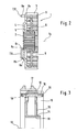
- FIG. 1 and Figure 2 show an embodiment of a hub according to the invention 1.
- the hub 1 is formed of a substantially cup-shaped sheet metal part and has a radially inwardly facing internal toothing 2.
- the inner toothing 2 is provided for engagement in a transmission shaft, not shown.
- At the sheet metal part is radially to directed outside an external toothing 3 provided for the engagement of a counter toothing on a shift sleeve, not shown.
- the bottom of the cup-shaped sheet metal part forms a wall 4 of the hub. From the wall 4 is inside a pointing in the longitudinal direction of the hub 1 and concentric with the outer teeth 3 arranged collar 5 from. At the inner diameter of the collar 5, the inner toothing 2 is formed. On the collar 5 outside sits a punched and cranked disc 6.
- the disc 6 forms the other wall of the hub 1.
- the hub 1 On the front side of the hub 1, the hub 1 with axially projecting and attached to the wall 4 of the hub 1 and the support width the hub 1 widening support elements 7 provided.
- There are three of the support elements 7 are arranged at a uniform distance from each other on the circumference of the hub 1.
- the support elements 7 close in the axial direction of the outer toothing 3.
- Each of the support elements 7 is formed by a molded part made of steel, wherein the molded part is a U-shaped bracket made of steel wire.
- the legs 8a and 8b of the bracket 8 are aligned parallel to the longitudinal center axis 1a of the hub.
- the free ends 8c and 8d of the legs 8a and 8b are welded to the wall 4 at the same distance from the longitudinal center axis 1a of the hub 1. Between the legs 8a and 8b of each bracket 8 runs to the bracket 8 out longitudinal groove 9 from.
- the longitudinal groove 9 is open radially outward.
- FIG. 3 shows a hub 10 with an inner toothing 11 and an outer toothing 12.
- the inner toothing 11 is formed on a collar 14 which is formed integrally with the hub 10 and is concentric with the longitudinal central axis 13 of the hub 10.
- a disc 15 is welded to the collar 14 and to the hub 10.
- a shift sleeve 17 is arranged longitudinally displaceable.
- the shift sleeve 17 is shown in its initial position.
- the pressure piece 16 rests axially on one side against a support element 18.
- the support member 18 is frontally attached to the hub 10 at the level of the outer teeth 12.
- the support member 18 limits the groove 19 in axial direction and limits the path of the pressure piece 16 in an axial direction.
- the shift sleeve is seated radially on the support element 18.
Landscapes
- Engineering & Computer Science (AREA)
- General Engineering & Computer Science (AREA)
- Mechanical Engineering (AREA)
- Mechanical Operated Clutches (AREA)
Description
- Die Erfindung betrifft eine Nabe einer Schaltkupplung, die Nabe gebildet aus wenigstens einem im Wesentlichen schalenförmig ausgebildeten Blechformteil mit einer geformten inneren Verzahnung für den Eingriff in eine Getriebewelle und einer äußeren Verzahnung für den Eingriff einer Gegenverzahnung an einer Schaltmuffe auf der Nabe.
- Aus Blechformteilen gebildete Naben zeichnen sich insbesondere durch die sparsame Verwendung von Material bei ihrer Herstellung und durch geringes Gewicht aus. Eine gattungsgemäße Nabe ist in DE 19942056 offenbart. In US 4,131,032 A ist eine derartige Nabe beschrieben, die insbesondere in unsynchronisierten oder synchronisierten Schaltkupplungen von Fahrzeuggetrieben eingesetzt ist. Ein rotationssymmetrisch und schalenförmig ausgebildetes Blechformteil ist innen und außen jeweils mit einer in Längsrichtung der Nabe ausgerichteten Verzahnung versehen. Die innere Verzahnung ist an einem vom Boden des Napfes abgehenden, in Längsrichtung der Nabe weisenden und konzentrisch zur äußeren Verzahnung angeordneten Bund ausgebildet. Auf dem Bund sitzt eine Scheibe mit Z-förmigem Querschnitt, die außen von der äußeren Verzahnung umgriffen ist. Die Scheibe ist an dem Blechformteil verschweißt und erhöht die Festigkeit bzw. Steifigkeit der Nabe.
- Die Breite der Nabe und die Breite der Verzahnung sind abhängig von den Belastungen an der Nabe während der Übertragung von Drehmomenten, wenn die auf der Welle sitzende Nabe und ein Gangrad mit der Schaltmuffe verbunden sind. Die Breite der Nabe ist jedoch auch durch die Schaltwege der Schaltmuffe auf der Nabe bestimmt. Bei den häufiger auftretenden Schaltkupplungen zwischen zwei wahlweise zu schaltenden Gangrädern sitzt die Schaltmuffe aus einer ungeschalteten Mittelstellung in Längsrichtung nach links und rechts schaltbar auf der Nabe. In der Mittelstellung sitzt die Schaltmuffe damit durch die Breite der Verzahnung gut geführt und gestützt verkippsicher auf der Nabe. Nach links oder rechts für eine wahlweise Verbindung mit einem der Gangräder verschoben, trägt nur noch ein links oder rechts liegender Anteil der Verzahnung an der Nabe die Schaltmuffe. Nur dieser Anteil überträgt dann auch die Drehmomente.
- Weniger häufig sind Schaltkupplungen, mit denen nur zu einer Seite geschaltet wird. Diese Schaltkupplungen dienen z. B. für das Schalten eines sogenannten Overdrive oder für das Verbinden der Schaltwelle mit einem Rückwärtsgang. In diesen Anwendungen sitzt die Schaltmuffe in einer von den Gangrädern gelösten Ausgangsstellung gut geführt und gestützt auch auf einer in der Regel die gesamte Breite der Nabe einnehmenden Verzahnung. Die Nabe muss dann entsprechend breit ausgeführt sein um ein sicheres Führen und Abstützen der Schaltmuffe in der Ausgangsstellung zu gewährleisten. Hierzu müssen überflüssig viel Bauraum im Getriebe und das entsprechende Material für die Fertigung der Nabe geopfert werden. Außerdem lassen sich an den spanlos gefertigten Naben des Standes der Technik in Längsrichtung über die Stirnseite der Nabe hinaus ausladende Konturen schwer verwirklichen.
- Die Aufgabe der Erfindung ist es daher, eine Nabe zu schaffen, mit der die vorgenannten Nachteile vermieden werden.
- Die Aufgabe ist nach dem kennzeichnenden Teil des Anspruches dadurch gelöst, dass die Nabe zumindest an einer Stirnseite der Nabe mit axial hervorstehenden und an der Nabe sowie die Stützbreite der Nabe zur Schaltmuffe verbreiternden Stützelementen versehen ist. Eine Nabe gemäß Erfindung muss jetzt nur noch so breit gefertigt werden, wie es der tragende Anteil der Verzahnung im eingerückten Zustand der Schaltmuffe erfordert. In der von dem Gangrad gelösten Ausgangsstellung sitzt die Schaltmuffe zu der einen Längsseite anteilig auf der Verzahnung, ragt über die Nabe hinaus und stützt sich ansonsten an den Stützelementen ab. Dazu schließen sich die Stützelemente vorzugsweise in axialer Richtung radial außenliegend an die äußere Verzahnung an. Für ein sicheres Abstützen der Schaltmuffe an der Nabe sind bevorzugt drei der Stützelemente in möglichst gleichmäßigen Abstand am Umfang der Nabe angeordnet.
- Die Stützelemente sind vorzugsweise jeweils durch ein Formteil aus Stahl gebildet. Derartige Formteile lassen sich, insbesondere in der Massenfertigung, schnell und kostengünstig in den verschiedensten Formen ihrer Gestalt herstellen.
- So ist dann auch in einer bevorzugten Ausgestaltung der Erfindung vorgesehen, dass das Stützelement ein U-förmiger Bügel aus Draht ist. Weiter ausgestaltet sieht die Erfindung vor, dass die Schenkel des Bügels parallel zu der Längsmittelachse der Nabe ausgerichtet sowie die freien Enden der Schenkel eines Bügels mit dem gleichen Abstand von der Längsmittelachse der Nabe an der Nabe verschweißt sind. Die Bügel ragen über die Stirnseite der Nabe hinaus und verbreitern die Stützbreite der Nabe für den Sitz der Schaltmuffe in ihrer Ausgangsstellung. Dabei sitzt die Schaltmuffe zumindest im nichtgeschalteten Zustand vorzugsweise auf den Bügeln auf.
- In einer weiteren Ausgestaltung der Erfindung ist vorgesehen, dass zwischen den Schenkeln eines Bügels in den Bügel eine zum Bügel hin offene Längsnut der Nabe ausläuft. Die Längsnut verläuft radial nach außen offen und die Verzahnung in Umfangsrichtung unterbrechend. Die Bügel sitzen mit jeweils einem Schenkel an einer seitlichen Flanke der durch die Längsnut gebildeten Öffnung an der Stirnseite der Nabe. Außer der Verbreiterung der Stützweite der Nabe dienen die Bügel oder andere Stützelemente als axiale Wegbegrenzung einer Längsnut in der Nabe. In einer derartigen Längsnut sind beispielsweise die Druckstücke für den Vorsynchronisationsprozess einer synchronisierten Schaltkupplung aufgenommen, wie auch eine Ausgestaltung der Erfindung vorsieht.
- Die Erfindung wird nachfolgend anhand von zwei Ausführungsbeispielen näher erläutert. Es zeigen:
- Figur 1
- ein Ausführungsbeispiel einer erfindungsgemäßen Nabe,
- Figur 2
- die Nabe nach Figur 1 in einem nicht maßstäblich dargestellten Längsschnitt und
- Figur 3
- ein weiteres Ausführungsbeispiel einer erfindungsgemäßen Nabe mit Druckstücken und einer Schaltmuffe, dargestellt in einem Halbschnitt.
- Figur 1 und Figur 2 zeigen ein Ausführungsbeispiel einer erfindungsgemäßen Nabe 1. Die Nabe 1 ist aus einem im Wesentlichen schalenförmig ausgebildeten Blechformteil gebildet und weist eine radial nach innen weisende innere Verzahnung 2 auf. Die innere Verzahnung 2 ist für den Eingriff in eine nicht dargestellte Getriebewelle vorgesehen. An dem Blechformteil ist radial nach außen gerichtet eine äußere Verzahnung 3 für den Eingriff einer Gegenverzahnung an einer nicht dargestellten Schaltmuffe vorgesehen. Der Boden des schalenförmigen Blechformteiles bildet eine Wandung 4 der Nabe. Von der Wandung 4 geht innen ein in Längsrichtung der Nabe 1 weisender und konzentrisch zur äußeren Verzahnung 3 angeordneter Bund 5 ab. Am Innendurchmesser des Bundes 5 ist die innere Verzahnung 2 ausgebildet. Auf dem Bund 5 außen sitzt eine gestanzte und gekröpft geformte Scheibe 6. Die Scheibe 6 bildet die andere Wand der Nabe 1. An der Stirnseite der Nabe 1 ist die Nabe 1 mit axial hervorstehenden und an der Wand 4 der Nabe 1 befestigten sowie die Stützbreite der Nabe 1 verbreiternden Stützelementen 7 versehen. Es sind drei der Stützelemente 7 mit gleichmäßigem Abstand zueinander am Umfang der Nabe 1 angeordnet. Die Stützelemente 7 schließen sich in axialer Richtung an die äußere Verzahnung 3 an. Jedes der Stützelemente 7 ist durch ein Formteil aus Stahl gebildet wobei das Formteil ein U-förmig ausgebildeter Bügel aus Stahldraht ist. Die Schenkel 8a und 8b des Bügels 8 sind parallel zu der Längsmittelachse 1a der Nabe ausgerichtet. Die freien Enden 8c und 8d der Schenkel 8a und 8b sind mit dem gleichen Abstand von der Längsmittelachse 1a der Nabe 1 an der Wand 4 verschweißt. Zwischen den Schenkeln 8a und 8b eines jeden Bügels 8 läuft eine zum Bügel 8 hin offene Längsnut 9 aus. Die Längsnut 9 ist radial nach außen geöffnet.
- Figur 3 zeigt eine Nabe 10 mit einer inneren Verzahnung 11 und einer äußeren Verzahnung 12. Die innere Verzahnung 11 ist an einem einteilig mit der Nabe 10 ausgebildeten konzentrisch zur Längsmittelachse 13 der Nabe 10 angeordneten Bund 14 ausgebildet. Auf dem Bund 14 sitzt eine Scheibe 15. Die Scheibe 15 ist an dem Bund 14 und an der Nabe 10 verschweißt. In einer in Längsrichtung durchgehenden Längsnut 19 sitzt ein in eine Richtung axial verschiebbares Druckstück 16. Auf der äußeren Verzahnung 12 ist eine Schaltmuffe 17 längsverschiebbar angeordnet. Die Schaltmuffe 17 ist in ihrer Ausgangsstellung dargestellt. Das Druckstück 16 liegt dabei axial zu einer Seite an einem Stützelement 18 an. Das Stützelement 18 ist stirnseitig an der Nabe 10 auf Höhe der äußeren Verzahnung 12 befestigt. Das Stützelement 18 begrenzt die Nut 19 in axialer Richtung und begrenzt den Weg des Druckstücks 16 in eine axiale Richtung. Die Schaltmuffe sitzt radial auf dem Stützelement 18 auf.
-
- 1
- Nabe
- 1a
- Längsmittelachse
- 2
- innere Verzahnung
- 3
- äußere Verzahnung
- 4
- Wandung
- 5
- Bund
- 6
- Scheibe
- 7
- Stützelement
- 8
- Bügel
- 8a
- Schenkel
- 8b
- Schenkel
- 8c
- Ende
- 8d
- Ende
- 9
- Längsnut
- 10
- Nabe
- 11
- innere Verzahnung
- 12
- äußere Verzahnung
- 13
- Längsmittelachse
- 14
- Bund
- 15
- Scheibe
- 16
- Druckstück
- 17
- Schaltmuffe
- 18
- Stützelement
- 19
- Längsnut
Claims (8)
- Nabe (1, 10) einer Schaltkupplung, wobei die Nabe (1, 10) aus wenigstens einem im Wesentlichen schalenförmig ausgebildeten Blechformteil mit einer geformten inneren Verzahnung (2, 11) für den Eingriff in eine Getriebewelle und mit einer äußeren Verzahnung (3, 12) für den Eingriff einer Gegenverzahnung an einer Schaltmuffe (17) auf der Nabe (10) besteht, dadurch gekennzeichnet, dass die Nabe (1, 10) zumindest an einer Stirnseite mit axial hervorstehenden und an ihr befestigten sowie die Stützbreite der Nabe (1, 10) in Bezug auf die Schaltmuffe (17) verbreiternden Stützelementen (7, 18) versehen ist.
- Nabe nach Anspruch 1, dadurch gekennzeichnet, dass jedes der Stützelemente (7, 18) sich in axiale Richtung der äußeren Verzahnung (3, 12) anschließt.
- Nabe nach Anspruch 1 und 2, dadurch gekennzeichnet, dass jedes der Stützelemente (7, 18) durch ein Formteil aus Stahl gebildet ist.
- Nabe nach Anspruch 3, dadurch gekennzeichnet, dass das Stützelement (7) ein U-förmig ausgebildeter Bügel (8) aus Draht ist.
- Nabe nach Anspruch 4, dadurch gekennzeichnet, dass die Schenkel (8a, 8b) des Bügels (8) parallel zu der Längsmittelachse der Nabe (1) ausgerichtete sowie die freien Enden (8c) der Schenkel (8a, 8b) wenigstens eines Bügels (8) mit dem gleichen Abstand von der Längsmittelachse der Nabe (1) an der Nabe (1) verschweißt sind.
- Nabe nach Anspruch 3, dadurch gekennzeichnet, dass die Schaltmuffe (17) zumindest zeitweise auf dem Stützelement (18) aufsitzt.
- Nabe nach Anspruch 5, dadurch gekennzeichnet, dass eine zum Bügel (8) hin offene Längsnut (9) in der Nabe (10) zwischen den Schenkeln (8a, 8b) wenigstens eines Bügels (8) in den Bügel (8) ausläuft.
- Nabe nach Anspruch 3, dadurch gekennzeichnet, dass in eine Längsnut (19) ein in Längsrichtung der Nabe (10) verschiebbares Druckstück (16) einer synchronisierten Schaltkupplung aufgenommen ist und dass das Stützelement (18) den Weg des Druckstückes (16) zumindest in axiale Richtung begrenzt.
Applications Claiming Priority (2)
| Application Number | Priority Date | Filing Date | Title |
|---|---|---|---|
| DE10120228A DE10120228A1 (de) | 2001-04-25 | 2001-04-25 | Nabe einer Schaltkupplung |
| DE10120228 | 2001-04-25 |
Publications (3)
| Publication Number | Publication Date |
|---|---|
| EP1253340A2 EP1253340A2 (de) | 2002-10-30 |
| EP1253340A3 EP1253340A3 (de) | 2004-03-03 |
| EP1253340B1 true EP1253340B1 (de) | 2006-06-14 |
Family
ID=7682654
Family Applications (1)
| Application Number | Title | Priority Date | Filing Date |
|---|---|---|---|
| EP02005557A Expired - Lifetime EP1253340B1 (de) | 2001-04-25 | 2002-03-12 | Nabe einer Schaltkupplung |
Country Status (4)
| Country | Link |
|---|---|
| EP (1) | EP1253340B1 (de) |
| AT (1) | ATE330140T1 (de) |
| BR (1) | BR0201405B1 (de) |
| DE (2) | DE10120228A1 (de) |
Families Citing this family (1)
| Publication number | Priority date | Publication date | Assignee | Title |
|---|---|---|---|---|
| DE102012223694B4 (de) * | 2012-10-17 | 2020-02-13 | Schaeffler Technologies AG & Co. KG | Verfahren zur Herstellung eines Muffenträgers |
Family Cites Families (7)
| Publication number | Priority date | Publication date | Assignee | Title |
|---|---|---|---|---|
| FR64076E (fr) * | 1953-09-24 | 1955-10-20 | Renault | Dispositif d'accouplement pour véhicules |
| US4131032A (en) | 1977-06-02 | 1978-12-26 | Borg-Warner Limited | Rotary drive member |
| FR2672950B1 (fr) * | 1991-02-19 | 1995-08-18 | Renault | Synchroniseur a dentures de moyeu et de baladeur etagees. |
| DE19623773A1 (de) * | 1996-06-14 | 1997-12-18 | Audi Ag | Zahnrad |
| DE19917230A1 (de) * | 1999-04-16 | 2000-10-19 | Schaeffler Waelzlager Ohg | Gebauter Synchronkörper mit Anschlagelement |
| DE19942056A1 (de) * | 1999-09-03 | 2001-03-08 | Schaeffler Waelzlager Ohg | Synchronkörper aus einem Formteil aus Blech |
| DE10010076A1 (de) * | 1999-11-18 | 2001-05-23 | Schaeffler Waelzlager Ohg | Synchronkörper für ein Schaltgetriebe |
-
2001
- 2001-04-25 DE DE10120228A patent/DE10120228A1/de not_active Withdrawn
-
2002
- 2002-03-12 AT AT02005557T patent/ATE330140T1/de not_active IP Right Cessation
- 2002-03-12 DE DE50207160T patent/DE50207160D1/de not_active Expired - Lifetime
- 2002-03-12 EP EP02005557A patent/EP1253340B1/de not_active Expired - Lifetime
- 2002-04-24 BR BRPI0201405-0A patent/BR0201405B1/pt not_active IP Right Cessation
Also Published As
| Publication number | Publication date |
|---|---|
| ATE330140T1 (de) | 2006-07-15 |
| EP1253340A3 (de) | 2004-03-03 |
| EP1253340A2 (de) | 2002-10-30 |
| BR0201405B1 (pt) | 2011-01-11 |
| BR0201405A (pt) | 2003-06-10 |
| DE10120228A1 (de) | 2002-10-31 |
| DE50207160D1 (de) | 2006-07-27 |
Similar Documents
| Publication | Publication Date | Title |
|---|---|---|
| DE102008040123A1 (de) | Getriebevorrichtung mit wenigstens einem Planetenradsatz und einem reibschlüssigen Schaltelement | |
| DE2848284C2 (de) | Getriebe für einen landwirtschaftlich genutzten Traktor mit Vierradantrieb | |
| EP0875689A2 (de) | Synchronisiervorrichtung | |
| EP2012035B1 (de) | Arretierung | |
| DE102011004415B4 (de) | Schaltwelle mit einer offenen Hülse sowie Hülse einer Schaltvorrichtung und Verfahren zu ihrer Herstellung | |
| DE102005025569A1 (de) | Sperrsynchronisierung | |
| EP1175569B1 (de) | Gebauter synchronkörper mit anschlagelement | |
| DE3808025A1 (de) | Schalthebel | |
| DE2848288A1 (de) | Synchronisiereinrichtung fuer ein kfz-getriebe | |
| DE3225364A1 (de) | Synchronring fuer eine synchronisiereinrichtung | |
| DE102005053989B4 (de) | Verfahren zur Herstellung eines Kupplungskörpers | |
| EP1253340A2 (de) | Nabe einer Schaltkupplung | |
| DE102006060534A1 (de) | Synchronisiervorrichtung eines Wechselschaltgetriebes | |
| DE102011005675A1 (de) | Schaltvorrichtung | |
| DE102010036277A1 (de) | Kupplungskörper für ein Gangrad eines Schaltgetriebes sowie Gangrad mit Kupplungskörper | |
| DE102010036280B4 (de) | Transmitter für eine Synchronisierungsbaugruppe eines Schaltgetriebes | |
| WO2014059981A1 (de) | Schaltvorrichtung eines kraftfahrzeugwechselgetriebes | |
| EP1208313B1 (de) | Synchronkörper aus einem formteil aus blech | |
| DE102014204897A1 (de) | Rastvorrichtung sowie Getriebeanordnung mit der Rastvorrichtung | |
| DE102013221246A1 (de) | Synchronkörper | |
| EP3685063B1 (de) | Synchronisierungseinheit | |
| DE102014213133B4 (de) | Schiebemuffe für eine Synchronisationsvorrichtung sowie Synchronisationsvorrichtung mit der Schiebemuffe | |
| DE10213669A1 (de) | Kupplungskörper zur Konussynchronisierung | |
| WO2015067247A1 (de) | Planetengetriebe mit stoffschlüssig verbundenem planetenträger | |
| DE102016217578A1 (de) | Schaltvorrichtung |
Legal Events
| Date | Code | Title | Description |
|---|---|---|---|
| PUAI | Public reference made under article 153(3) epc to a published international application that has entered the european phase |
Free format text: ORIGINAL CODE: 0009012 |
|
| 17P | Request for examination filed |
Effective date: 20020312 |
|
| AK | Designated contracting states |
Kind code of ref document: A2 Designated state(s): AT BE CH CY DE DK ES FI FR GB GR IE IT LI LU MC NL PT SE TR |
|
| AX | Request for extension of the european patent |
Free format text: AL;LT;LV;MK;RO;SI |
|
| PUAL | Search report despatched |
Free format text: ORIGINAL CODE: 0009013 |
|
| AK | Designated contracting states |
Kind code of ref document: A3 Designated state(s): AT BE CH CY DE DK ES FI FR GB GR IE IT LI LU MC NL PT SE TR |
|
| AX | Request for extension of the european patent |
Extension state: AL LT LV MK RO SI |
|
| 17Q | First examination report despatched |
Effective date: 20040421 |
|
| AKX | Designation fees paid |
Designated state(s): AT BE CH CY DE DK ES FI FR GB GR IE IT LI LU MC NL PT SE TR |
|
| GRAP | Despatch of communication of intention to grant a patent |
Free format text: ORIGINAL CODE: EPIDOSNIGR1 |
|
| GRAS | Grant fee paid |
Free format text: ORIGINAL CODE: EPIDOSNIGR3 |
|
| RAP1 | Party data changed (applicant data changed or rights of an application transferred) |
Owner name: SCHAEFFLER KG |
|
| GRAA | (expected) grant |
Free format text: ORIGINAL CODE: 0009210 |
|
| AK | Designated contracting states |
Kind code of ref document: B1 Designated state(s): AT BE CH CY DE DK ES FI FR GB GR IE IT LI LU MC NL PT SE TR |
|
| PG25 | Lapsed in a contracting state [announced via postgrant information from national office to epo] |
Ref country code: IT Free format text: LAPSE BECAUSE OF FAILURE TO SUBMIT A TRANSLATION OF THE DESCRIPTION OR TO PAY THE FEE WITHIN THE PRESCRIBED TIME-LIMIT;WARNING: LAPSES OF ITALIAN PATENTS WITH EFFECTIVE DATE BEFORE 2007 MAY HAVE OCCURRED AT ANY TIME BEFORE 2007. THE CORRECT EFFECTIVE DATE MAY BE DIFFERENT FROM THE ONE RECORDED. Effective date: 20060614 Ref country code: IE Free format text: LAPSE BECAUSE OF FAILURE TO SUBMIT A TRANSLATION OF THE DESCRIPTION OR TO PAY THE FEE WITHIN THE PRESCRIBED TIME-LIMIT Effective date: 20060614 Ref country code: FI Free format text: LAPSE BECAUSE OF FAILURE TO SUBMIT A TRANSLATION OF THE DESCRIPTION OR TO PAY THE FEE WITHIN THE PRESCRIBED TIME-LIMIT Effective date: 20060614 Ref country code: NL Free format text: LAPSE BECAUSE OF FAILURE TO SUBMIT A TRANSLATION OF THE DESCRIPTION OR TO PAY THE FEE WITHIN THE PRESCRIBED TIME-LIMIT Effective date: 20060614 |
|
| REG | Reference to a national code |
Ref country code: GB Ref legal event code: FG4D Free format text: NOT ENGLISH |
|
| REG | Reference to a national code |
Ref country code: CH Ref legal event code: EP |
|
| REG | Reference to a national code |
Ref country code: IE Ref legal event code: FG4D Free format text: LANGUAGE OF EP DOCUMENT: GERMAN |
|
| REF | Corresponds to: |
Ref document number: 50207160 Country of ref document: DE Date of ref document: 20060727 Kind code of ref document: P |
|
| PG25 | Lapsed in a contracting state [announced via postgrant information from national office to epo] |
Ref country code: DK Free format text: LAPSE BECAUSE OF FAILURE TO SUBMIT A TRANSLATION OF THE DESCRIPTION OR TO PAY THE FEE WITHIN THE PRESCRIBED TIME-LIMIT Effective date: 20060914 Ref country code: SE Free format text: LAPSE BECAUSE OF FAILURE TO SUBMIT A TRANSLATION OF THE DESCRIPTION OR TO PAY THE FEE WITHIN THE PRESCRIBED TIME-LIMIT Effective date: 20060914 |
|
| PG25 | Lapsed in a contracting state [announced via postgrant information from national office to epo] |
Ref country code: ES Free format text: LAPSE BECAUSE OF FAILURE TO SUBMIT A TRANSLATION OF THE DESCRIPTION OR TO PAY THE FEE WITHIN THE PRESCRIBED TIME-LIMIT Effective date: 20060925 |
|
| GBT | Gb: translation of ep patent filed (gb section 77(6)(a)/1977) |
Effective date: 20060923 |
|
| PG25 | Lapsed in a contracting state [announced via postgrant information from national office to epo] |
Ref country code: PT Free format text: LAPSE BECAUSE OF FAILURE TO SUBMIT A TRANSLATION OF THE DESCRIPTION OR TO PAY THE FEE WITHIN THE PRESCRIBED TIME-LIMIT Effective date: 20061114 |
|
| NLV1 | Nl: lapsed or annulled due to failure to fulfill the requirements of art. 29p and 29m of the patents act | ||
| ET | Fr: translation filed | ||
| REG | Reference to a national code |
Ref country code: IE Ref legal event code: FD4D |
|
| PLBE | No opposition filed within time limit |
Free format text: ORIGINAL CODE: 0009261 |
|
| STAA | Information on the status of an ep patent application or granted ep patent |
Free format text: STATUS: NO OPPOSITION FILED WITHIN TIME LIMIT |
|
| 26N | No opposition filed |
Effective date: 20070315 |
|
| REG | Reference to a national code |
Ref country code: CH Ref legal event code: PL |
|
| BERE | Be: lapsed |
Owner name: SCHAEFFLER K.G. Effective date: 20070331 |
|
| PG25 | Lapsed in a contracting state [announced via postgrant information from national office to epo] |
Ref country code: BE Free format text: LAPSE BECAUSE OF NON-PAYMENT OF DUE FEES Effective date: 20070331 |
|
| PG25 | Lapsed in a contracting state [announced via postgrant information from national office to epo] |
Ref country code: MC Free format text: LAPSE BECAUSE OF NON-PAYMENT OF DUE FEES Effective date: 20070331 |
|
| PG25 | Lapsed in a contracting state [announced via postgrant information from national office to epo] |
Ref country code: LI Free format text: LAPSE BECAUSE OF NON-PAYMENT OF DUE FEES Effective date: 20070331 Ref country code: CH Free format text: LAPSE BECAUSE OF NON-PAYMENT OF DUE FEES Effective date: 20070331 |
|
| PG25 | Lapsed in a contracting state [announced via postgrant information from national office to epo] |
Ref country code: GR Free format text: LAPSE BECAUSE OF FAILURE TO SUBMIT A TRANSLATION OF THE DESCRIPTION OR TO PAY THE FEE WITHIN THE PRESCRIBED TIME-LIMIT Effective date: 20060915 |
|
| PGFP | Annual fee paid to national office [announced via postgrant information from national office to epo] |
Ref country code: GB Payment date: 20080312 Year of fee payment: 7 Ref country code: IT Payment date: 20080321 Year of fee payment: 7 |
|
| PG25 | Lapsed in a contracting state [announced via postgrant information from national office to epo] |
Ref country code: AT Free format text: LAPSE BECAUSE OF NON-PAYMENT OF DUE FEES Effective date: 20070312 |
|
| PG25 | Lapsed in a contracting state [announced via postgrant information from national office to epo] |
Ref country code: CY Free format text: LAPSE BECAUSE OF FAILURE TO SUBMIT A TRANSLATION OF THE DESCRIPTION OR TO PAY THE FEE WITHIN THE PRESCRIBED TIME-LIMIT Effective date: 20060614 Ref country code: LU Free format text: LAPSE BECAUSE OF NON-PAYMENT OF DUE FEES Effective date: 20070312 |
|
| PG25 | Lapsed in a contracting state [announced via postgrant information from national office to epo] |
Ref country code: TR Free format text: LAPSE BECAUSE OF FAILURE TO SUBMIT A TRANSLATION OF THE DESCRIPTION OR TO PAY THE FEE WITHIN THE PRESCRIBED TIME-LIMIT Effective date: 20060614 |
|
| GBPC | Gb: european patent ceased through non-payment of renewal fee |
Effective date: 20090312 |
|
| PG25 | Lapsed in a contracting state [announced via postgrant information from national office to epo] |
Ref country code: GB Free format text: LAPSE BECAUSE OF NON-PAYMENT OF DUE FEES Effective date: 20090312 |
|
| PG25 | Lapsed in a contracting state [announced via postgrant information from national office to epo] |
Ref country code: IT Free format text: LAPSE BECAUSE OF NON-PAYMENT OF DUE FEES Effective date: 20090312 |
|
| REG | Reference to a national code |
Ref country code: DE Ref legal event code: R081 Ref document number: 50207160 Country of ref document: DE Owner name: SCHAEFFLER TECHNOLOGIES AG & CO. KG, DE Free format text: FORMER OWNER: SCHAEFFLER TECHNOLOGIES GMBH & CO. KG, 91074 HERZOGENAURACH, DE Effective date: 20120828 Ref country code: DE Ref legal event code: R081 Ref document number: 50207160 Country of ref document: DE Owner name: SCHAEFFLER TECHNOLOGIES GMBH & CO. KG, DE Free format text: FORMER OWNER: SCHAEFFLER TECHNOLOGIES GMBH & CO. KG, 91074 HERZOGENAURACH, DE Effective date: 20120828 |
|
| REG | Reference to a national code |
Ref country code: DE Ref legal event code: R081 Ref document number: 50207160 Country of ref document: DE Owner name: SCHAEFFLER TECHNOLOGIES GMBH & CO. KG, DE Free format text: FORMER OWNER: SCHAEFFLER TECHNOLOGIES AG & CO. KG, 91074 HERZOGENAURACH, DE Effective date: 20140218 Ref country code: DE Ref legal event code: R081 Ref document number: 50207160 Country of ref document: DE Owner name: SCHAEFFLER TECHNOLOGIES AG & CO. KG, DE Free format text: FORMER OWNER: SCHAEFFLER TECHNOLOGIES AG & CO. KG, 91074 HERZOGENAURACH, DE Effective date: 20140218 |
|
| REG | Reference to a national code |
Ref country code: DE Ref legal event code: R081 Ref document number: 50207160 Country of ref document: DE Owner name: SCHAEFFLER TECHNOLOGIES AG & CO. KG, DE Free format text: FORMER OWNER: SCHAEFFLER TECHNOLOGIES GMBH & CO. KG, 91074 HERZOGENAURACH, DE Effective date: 20150210 |
|
| REG | Reference to a national code |
Ref country code: FR Ref legal event code: PLFP Year of fee payment: 14 |
|
| REG | Reference to a national code |
Ref country code: FR Ref legal event code: PLFP Year of fee payment: 15 |
|
| PGFP | Annual fee paid to national office [announced via postgrant information from national office to epo] |
Ref country code: FR Payment date: 20160330 Year of fee payment: 15 |
|
| PGFP | Annual fee paid to national office [announced via postgrant information from national office to epo] |
Ref country code: DE Payment date: 20160531 Year of fee payment: 15 |
|
| REG | Reference to a national code |
Ref country code: DE Ref legal event code: R119 Ref document number: 50207160 Country of ref document: DE |
|
| REG | Reference to a national code |
Ref country code: FR Ref legal event code: ST Effective date: 20171130 |
|
| PG25 | Lapsed in a contracting state [announced via postgrant information from national office to epo] |
Ref country code: DE Free format text: LAPSE BECAUSE OF NON-PAYMENT OF DUE FEES Effective date: 20171003 Ref country code: FR Free format text: LAPSE BECAUSE OF NON-PAYMENT OF DUE FEES Effective date: 20170331 |
|
| P01 | Opt-out of the competence of the unified patent court (upc) registered |
Effective date: 20230522 |