EP1253045A1 - Vorrichtung zum Festsetzen eines Anbauelements an eine Aufbaustruktur eines Kraftfahrzeugs - Google Patents
Vorrichtung zum Festsetzen eines Anbauelements an eine Aufbaustruktur eines Kraftfahrzeugs Download PDFInfo
- Publication number
- EP1253045A1 EP1253045A1 EP02005715A EP02005715A EP1253045A1 EP 1253045 A1 EP1253045 A1 EP 1253045A1 EP 02005715 A EP02005715 A EP 02005715A EP 02005715 A EP02005715 A EP 02005715A EP 1253045 A1 EP1253045 A1 EP 1253045A1
- Authority
- EP
- European Patent Office
- Prior art keywords
- profile
- elements
- vehicle body
- longitudinal
- support profile
- Prior art date
- Legal status (The legal status is an assumption and is not a legal conclusion. Google has not performed a legal analysis and makes no representation as to the accuracy of the status listed.)
- Granted
Links
Images




Classifications
-
- B—PERFORMING OPERATIONS; TRANSPORTING
- B60—VEHICLES IN GENERAL
- B60R—VEHICLES, VEHICLE FITTINGS, OR VEHICLE PARTS, NOT OTHERWISE PROVIDED FOR
- B60R3/00—Arrangements of steps or ladders facilitating access to or on the vehicle, e.g. running-boards
- B60R3/002—Running boards
Definitions
- the invention relates to a device for fixing an add-on element, in particular a running board or sill paneling on a body structure of a motor vehicle according to the preamble of patent claim 1.
- the object of the invention is to provide an improved device for fixing Add-on elements, such as a running board or sill paneling on a body structure to create a motor vehicle that is easy to assemble and replace and ensures a stable attachment to the vehicle body and underbody protection forms.
- Add-on elements such as a running board or sill paneling on a body structure to create a motor vehicle that is easy to assemble and replace and ensures a stable attachment to the vehicle body and underbody protection forms.
- Running board or sill paneling can be easily mounted on the vehicle and when using a running board, optimal tread resistance is guaranteed and the running board and the sill panel and a connected support profile at the same time protection of the underbody structure and aggregates is guaranteed.
- the structural elements have a strip-like support profile Corresponding profile longitudinal edges that are concave and convex in cross section that can be connected to each other.
- the carrier profile is on the one hand on Vehicle body spaced mounting brackets and on the other hand the fasteners on the support profile can be firmly connected to the vehicle body.
- the support profile consists of a hollow profile with a horizontally aligned tread, against which an inner rounded wall and connects an outer, approximately straight wall and to these two walls the profile longitudinal edge of the add-on element, which is concave in cross section, is connected at the end, which has the convex profile longitudinal edge of the carrier profile on both sides overlaps.
- the concave profile longitudinal edge of the add-on element has a for hooking connection angled leg lying on top, which is a profile edge of the convex Long edge of the profile of the support profile engages over a hook and a bottom one adjoining wall of the add-on element is rounded and on a corresponding wall of the longitudinal profile edge of the support profile rests. So that can Running board or the sill panel by swiveling in relation to the carrier profile be hooked into the longitudinal profile edge of the carrier profile or removed therefrom.
- the positive connection of the longitudinal profile edges can be between the add-on element and the support profile can be fixed by screws or rivets.
- the direct connection of the carrier profile to the vehicle body is made via the front, rear and middle area of the vehicle body Fastening brackets that are connected to the vehicle body, which Carrier profile can be attached to the vehicle body via additional fastening webs.
- the Fastening brackets are aligned approximately in a horizontal plane Screw-on surfaces for the support profile, with the holes for the Fixing screws approximately in a central vertical longitudinal plane of the support profile are arranged.
- the carrier profile can be used to cover an intermediate space between the longitudinal beam and Sill of the vehicle have a panel that the front Fastening bracket with.
- end caps To seal the open ends of the running board or the sill panel and the Support profiles are provided end caps, with the interposition of a Sealing element sealingly with the add-on element or the carrier profile get connected.
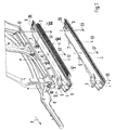
- the device 1 for fixing add-on elements, such as a running board 2 or one Sill panel 3 on the vehicle essentially comprises a support profile 4, the with fasteners or fastening tabs or the like.
- Means 5, 6 and 7 with the vehicle body is connected to the side member 8 and / or the sill 9. Furthermore, it is attached to brackets 10, 11 and 12.
- This Vehicle-fixed carrier profile 4 can either the footboard 2 or the Sill cover 3 by means of a hooking or hooking connection 13 between Longitudinal profile edges P1 and P2 of the support profile 4 and the footboard 2 and the Sill panel 3 are connected.
- the mounting brackets 10, 11 and 12 are over with the vehicle body Screws S2, S3, S4 are attached and these brackets have common horizontal Screw-on surfaces for the support profile 4.
- the screws S2, S3 and S4 are for this performed approximately in the middle of the support profile 4 in a vertical longitudinal plane X-X and in the mounting brackets 10, 11 and 12, for example, fixable in nuts.
- the carrier profile 4 On the front is the carrier profile 4 with a so-called cladding panel 20 provided which has a space between the side member 8 and the sill 9 should cover.
- the longitudinal profile edge P1 of the running board 2 or the rocker panel 3 is in Cross-section concavely profiled and the other corresponding with it Longitudinal profile edge P2 of the carrier profile 4 is convex in cross section and both Longitudinal profile edges P1 and P2 form the form-fitting hook-in or hook-in connection 13 between the carrier profile 4 on the one hand and the running board 2 or the Sill cover 3 on the other hand.
- the longitudinal profile edge P1 of the carrier profile 4 comprises one rounded to an inner one Wall 2b of the step surface 2a adjoining angled legs 21 lying on top, which is followed by a rounded wall 22 pointing downward. This forms with the leg 21, the concave recording of the longitudinal profile edge P1.
- noise-damping or vibration-damping plastic pads 24 are arranged, which are spaced apart can be located.
- a sealing element 25 is provided, on the subsequent end caps 26, 26a are arranged.
- a receptacle for a jack is integrated, which consists of a reinforcement 30, 31 can be used and which front and rear of the support profile 4 can be arranged, which is shown in Fig. 4a.
Landscapes
- Engineering & Computer Science (AREA)
- Mechanical Engineering (AREA)
- Body Structure For Vehicles (AREA)
- Vehicle Interior And Exterior Ornaments, Soundproofing, And Insulation (AREA)
- Lock And Its Accessories (AREA)
- Lens Barrels (AREA)
- Motor Or Generator Frames (AREA)
- Passenger Equipment (AREA)
Abstract
Description
- Fig. 1
- eine schaubildliche Darstellung der Vorrichtung mit einer Seitenwand des Fahrzeugs und einem ansetzbaren Trittbrett oder einer ansetzbaren Schwellerverkleidung an einem Trägerprofil,
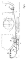
- Fig. 2
- eine Ansicht auf eine hintenliegende Befestigungskonsole für das Trägerprofil,
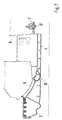
- Fig. 3
- eine Ansicht auf eine vornliegende und eine mittlere Befestigungskonsole für das Trägerprofil,
- Fig. 4
- eine schaubildliche Darstellung auf ein Trittbrett mit Endstücken und Schaumgummipads,
- Fig. 4a
- eine schaubildliche Darstellung des Trägerprofils mit Befestigungskonsolen und Befestigungselementen,
- Fig. 5
- einen Querschnitt durch das Trittbrett mit Trägerprofil und vorderen Befestigungselementen nach der Linie V-V der Fig. 1,
- Fig. 6
- einen Querschnitt durch das Trittbrett mit Trägerprofil und mittleren Befestigungssteg nach der Linie VI-VI der Fig. 1,
- Fig. 7
- einen Querschnitt durch das Trittbrett mit Trägerprofil und hintenliegendem Befestigungselement nach der Linie VII-VII der Fig. 1 und
- Fig. 8
- einen Querschnitt durch eine Schwellerverkleidung mit Trägerprofil.
Claims (9)
- Vorrichtung zum Festsetzen eines Anbauelements, insbesondere eines Trittbretts oder einer Schwellerverkleidung an eine Aufbaustruktur eines Kraftfahrzeugs mittels Befestigungselemente, wobei das Aufbauelement sich entlang eines Schwellers des Fahrzeugaufbaus erstreckt, dadurch gekennzeichnet, daß die Aufbauelemente (2; 3) auswechselbar mit einem leistenartigen Trägerprofil (4) über miteinander korrespondierende und im Querschnitt konkav und konvex ausgebildete Profillängskanten (P1, P2) an den Aufbauelementen (2; 3) und dem Trägerprofil (4) verbindbar sind und das Trägerprofil (4) einerseits über am Fahrzeugaufbau (8, 9) beabstandet angeordnete Befestigungskonsolen (10, 11, 12) und andererseits über die Befestigungselemente (5, 6, 7) am Trägerprofil (4) mit dem Fahrzeugaufbau (8, 9) verbindbar ist.
- Vorrichtung nach Anspruch 1, dadurch gekennzeichnet, daß das Trittbrett (2) aus mindestens einem Hohlprofil mit einer horizontal ausgerichteten Trittfläche (2a) besteht, an die sich eine innere ausgerundete Wand (2b) und eine äußere etwa geradlinig ausgeführte Wand (2c) anschließt und an diese beiden Wände (2b, 2c) sich endseitig die im Querschnitt konkave Profillängskante (P1) der Anbauelemente (2; 3) anschließt, welche die im Querschnitt konvexe Profillängskante (P2) des Trägerprofils (4) beidseitig übergreift.
- Vorrichtung nach den Ansprüchen 1 oder 2, dadurch gekennzeichnet, daß die konkave Profillängskante (P1) der Anbauelemente (2; 3) einen oben liegenden abgewinkelten Schenkel (21) umfaßt, der eine Profilkante (24) der konvexen Profillängskante (P2) des Trägerprofils (4) hakend übergreift und eine untenliegende anschließende Wand (22) der Anbauelemente (2; 3) ausgerundet ist und an einer korrespondierenden Wand (23) der Profillängskante (P2) des Trägerprofils (4) anliegt.
- Vorrichtung nach den Ansprüchen 1, 2 oder 3, dadurch gekennzeichnet, daß die Anbauelemente (2; 3) mit demTrägerprofil (4) zwischen den Profillängskanten (P1 und P2) miteinander über Schrauben oder Niete verbunden sind.
- Vorrichtung nach einem oder mehreren der vorhergehenden Ansprüche, dadurch gekennzeichnet, daß das Trägerprofil (4) über am vorderen, hinteren und mittleren Bereich des Fahrzeugaufbaus (8, 9) über Schrauben (S2, S3, S4) verbundene Befestigungskonsolen (10, 11, 12) an dem Fahrzeugaufbau (8, 9) über Schrauben (S1) befestigt ist und das Trägerprofil (4) zusätzlich über die Elemente (5, 6, 7) am Fahrzeugaufbau (8, 9) festsetzbar ist.
- Vorrichtung nach einem oder mehreren der vorhergehenden Ansprüche, dadurch gekennzeichnet, daß die Befestigungskonsolen (10, 11, 12) etwa in einer horizontalen Ebene ausgerichtete Anschraubflächen für das Trägerprofil (4) aufweisen, wobei die Bohrungen für die Befestigungsschrauben (S1) etwa in einer mittigen senkrechten Längsebene (X-X) des Trägerprofils (4) angeordnet sind.
- Vorrichtung nach einem oder mehreren der vorhergehenden Ansprüche, dadurch gekennzeichnet, daß mit dem Trägerprofil (4) ein Verbindungsblech (20) verbunden ist, in das die vordere Befestigungskonsole (5) integriert ist.
- Vorrichtung nach einem oder mehreren der vorhergehenden Ansprüche, dadurch gekennzeichnet, daß zwischen den Anbauelementen (2; 3) und dem Schweller (9) oder dem Längsträger (8) des Fahrzeugaufbaus beabstandete Schaumpolster (24) angeordnet sind.
- Vorrichtung nach einem oder mehreren der vorhergehenden Ansprüche, dadurch gekennzeichnet, daß die Anbauelemente (2; 3) am freien Ende mit einer Endkappe (26) abgeschlossen sind und ein Dichtelement (25) zwischen der Endkappe (26) und dem freien Ende der Anbauelemente (2; 3) vorgesehen ist.
Applications Claiming Priority (2)
| Application Number | Priority Date | Filing Date | Title |
|---|---|---|---|
| DE10120444A DE10120444C1 (de) | 2001-04-26 | 2001-04-26 | Vorrichtung zum Festsetzen eines Anbauelements an eine Aufbaustruktur eines Kraftfahrzeugs |
| DE10120444 | 2001-04-26 |
Publications (2)
| Publication Number | Publication Date |
|---|---|
| EP1253045A1 true EP1253045A1 (de) | 2002-10-30 |
| EP1253045B1 EP1253045B1 (de) | 2004-06-30 |
Family
ID=7682793
Family Applications (1)
| Application Number | Title | Priority Date | Filing Date |
|---|---|---|---|
| EP02005715A Expired - Lifetime EP1253045B1 (de) | 2001-04-26 | 2002-03-13 | Vorrichtung zum Festsetzen eines Anbauelements an eine Aufbaustruktur eines Kraftfahrzeugs |
Country Status (6)
| Country | Link |
|---|---|
| US (1) | US6688621B2 (de) |
| EP (1) | EP1253045B1 (de) |
| JP (1) | JP3692088B2 (de) |
| AT (1) | ATE270202T1 (de) |
| DE (2) | DE10120444C1 (de) |
| ES (1) | ES2219595T3 (de) |
Cited By (1)
| Publication number | Priority date | Publication date | Assignee | Title |
|---|---|---|---|---|
| CN104590394A (zh) * | 2015-01-16 | 2015-05-06 | 东风商用车有限公司 | 一种铝合金客车踏步区地板骨架连接结构 |
Families Citing this family (16)
| Publication number | Priority date | Publication date | Assignee | Title |
|---|---|---|---|---|
| JP3978711B2 (ja) * | 2001-12-28 | 2007-09-19 | スズキ株式会社 | スプラッシュガードの構造 |
| USD521439S1 (en) | 2003-03-03 | 2006-05-23 | Salflex Polymers Ltd. | Running board bracket |
| US7083179B2 (en) * | 2003-03-03 | 2006-08-01 | Salflex Polymers Ltd. | Running board |
| US20050012295A1 (en) * | 2003-07-16 | 2005-01-20 | Chevalier Donald P. | Two-component running board |
| USD497338S1 (en) | 2003-09-19 | 2004-10-19 | Ford Global Technologies, Llc | Vehicle running board |
| USD513725S1 (en) * | 2003-09-19 | 2006-01-24 | Ford Global Technologies, Llc | Vehicle running board |
| JP2005119434A (ja) * | 2003-10-16 | 2005-05-12 | Honda Motor Co Ltd | 自動車のガードパイプ |
| US7334807B2 (en) * | 2004-05-27 | 2008-02-26 | Steffens Enterprises, Inc. | Vehicle step tube |
| US7311320B2 (en) * | 2005-10-17 | 2007-12-25 | Magna International Inc. | One piece running board bracket |
| KR100732619B1 (ko) * | 2006-01-27 | 2007-06-27 | 주식회사 아펙스 | 레저 차량용 발판의 지지브라켓트 |
| WO2007147236A1 (en) * | 2006-06-21 | 2007-12-27 | Salflex Polymers Ltd. | Running board for vehicle |
| US7819412B2 (en) * | 2007-11-16 | 2010-10-26 | Load Rite Trailers, Inc. | Universal fender step |
| JP6139861B2 (ja) * | 2011-11-18 | 2017-05-31 | マグナ インターナショナル インコーポレイテッド | 自動ステップボード用ロッカーモール取付システム |
| EP3131784B1 (de) * | 2014-04-15 | 2018-12-12 | Tiercon Corp. | Verbundstofftrittbrett |
| US10518727B1 (en) | 2018-09-28 | 2019-12-31 | GM Global Technology Operations LLC | Step assembly for energy absorption |
| US11628866B2 (en) | 2020-12-04 | 2023-04-18 | Toyota Research Institute, Inc. | Systems, methods, and vehicles providing adaptive window transparency for vehicle mode switching |
Citations (4)
| Publication number | Priority date | Publication date | Assignee | Title |
|---|---|---|---|---|
| US5193829A (en) * | 1991-11-19 | 1993-03-16 | Warn Industries, Inc. | Sub frame support system and running board for a vehicle |
| US5382035A (en) * | 1993-04-19 | 1995-01-17 | Algonquin Industries International, Inc. | Vehicle running board assembly |
| DE29900510U1 (de) * | 1999-01-14 | 1999-08-12 | Haslbeck Technik GmbH, 84453 Mühldorf | Trägerkonstruktion zur Befestigung eines Formteils an einer Fahrzeugkarosserie |
| US6173979B1 (en) * | 1999-04-30 | 2001-01-16 | Bernard Mould Ltd. | Vehicle running board construction |
Family Cites Families (11)
| Publication number | Priority date | Publication date | Assignee | Title |
|---|---|---|---|---|
| US2208723A (en) * | 1939-05-22 | 1940-07-23 | Briggs Mfg Co | Scuff plate |
| JPS5649677U (de) * | 1979-09-25 | 1981-05-01 | ||
| US4456275A (en) * | 1982-02-12 | 1984-06-26 | Coachmen Industries, Inc. | Running board construction |
| US4451063A (en) * | 1982-02-12 | 1984-05-29 | Coachmen Industries, Inc. | Running board construction |
| DE9000526U1 (de) * | 1990-01-18 | 1990-03-01 | Holey, Gerda, 8442 Geiselhöring | Zier- und Schutzleiste für den Radlaufausschnitt in Kotflügeln von Kraftfahrzeugen |
| US5062665A (en) * | 1990-06-11 | 1991-11-05 | Adell Corporation | Door edge guard with J cross section |
| US5713589A (en) * | 1995-03-03 | 1998-02-03 | Smittybilt, Inc. | Side step for motor vehicle |
| US5823553A (en) * | 1996-05-21 | 1998-10-20 | Dfm Corporation | Running board accessory with flap seal |
| US5788321A (en) * | 1996-05-22 | 1998-08-04 | Freightliner Corporation | Removable side fairing for a vehicle |
| US5895064A (en) * | 1997-03-18 | 1999-04-20 | Laubach; Daniel J. | Universal mounting bracket for running boards |
| US6050579A (en) * | 1998-04-21 | 2000-04-18 | Aeroquip Corporation | Automotive running board |
-
2001
- 2001-04-26 DE DE10120444A patent/DE10120444C1/de not_active Expired - Fee Related
-
2002
- 2002-03-13 DE DE50200558T patent/DE50200558D1/de not_active Expired - Lifetime
- 2002-03-13 EP EP02005715A patent/EP1253045B1/de not_active Expired - Lifetime
- 2002-03-13 AT AT02005715T patent/ATE270202T1/de not_active IP Right Cessation
- 2002-03-13 ES ES02005715T patent/ES2219595T3/es not_active Expired - Lifetime
- 2002-03-25 JP JP2002083707A patent/JP3692088B2/ja not_active Expired - Fee Related
- 2002-04-23 US US10/127,656 patent/US6688621B2/en not_active Expired - Fee Related
Patent Citations (4)
| Publication number | Priority date | Publication date | Assignee | Title |
|---|---|---|---|---|
| US5193829A (en) * | 1991-11-19 | 1993-03-16 | Warn Industries, Inc. | Sub frame support system and running board for a vehicle |
| US5382035A (en) * | 1993-04-19 | 1995-01-17 | Algonquin Industries International, Inc. | Vehicle running board assembly |
| DE29900510U1 (de) * | 1999-01-14 | 1999-08-12 | Haslbeck Technik GmbH, 84453 Mühldorf | Trägerkonstruktion zur Befestigung eines Formteils an einer Fahrzeugkarosserie |
| US6173979B1 (en) * | 1999-04-30 | 2001-01-16 | Bernard Mould Ltd. | Vehicle running board construction |
Cited By (1)
| Publication number | Priority date | Publication date | Assignee | Title |
|---|---|---|---|---|
| CN104590394A (zh) * | 2015-01-16 | 2015-05-06 | 东风商用车有限公司 | 一种铝合金客车踏步区地板骨架连接结构 |
Also Published As
| Publication number | Publication date |
|---|---|
| US20020158439A1 (en) | 2002-10-31 |
| JP2002347665A (ja) | 2002-12-04 |
| EP1253045B1 (de) | 2004-06-30 |
| ES2219595T3 (es) | 2004-12-01 |
| JP3692088B2 (ja) | 2005-09-07 |
| US6688621B2 (en) | 2004-02-10 |
| DE50200558D1 (de) | 2004-08-05 |
| DE10120444C1 (de) | 2002-10-10 |
| ATE270202T1 (de) | 2004-07-15 |
Similar Documents
| Publication | Publication Date | Title |
|---|---|---|
| EP1253045B1 (de) | Vorrichtung zum Festsetzen eines Anbauelements an eine Aufbaustruktur eines Kraftfahrzeugs | |
| DE10023193B4 (de) | Fahrzeugaufbau für einen Vorderwagen eines Kraftfahrzeugs | |
| DE69904067T2 (de) | Trittbettbefestigungsbügel | |
| EP0222990B1 (de) | Türsystem für Kraftfahrzeuge | |
| DE10203055A1 (de) | Fußstütze für ein Fahrzeug | |
| DE10206768A1 (de) | Kotflügelanordnung für ein Kraftfahrzeug | |
| EP1243477A2 (de) | Aufnahme- und Verbindungsvorrichtung für eine Bug/Heckschürze eines Kraftfahrzeugs | |
| WO2004024538A1 (de) | Karosserie für einen kraftwagen mit einer dachsäule | |
| DE10051512A1 (de) | Fahrzeugdach | |
| DE8505038U1 (de) | Aerodynamische verkleidung an der unterseite von personenwagen | |
| DE10360170B3 (de) | Deformationselement für ein Kraftfahrzeug | |
| DE10302756B4 (de) | Tragstruktur für eine Kraftwagenkarosserie | |
| DE10304016A1 (de) | Dachreling für ein Fahrzeug und Fahrzeugdach | |
| DE19711598B4 (de) | Kraftfahrzeugtür | |
| EP0327728B1 (de) | Stossfangvorrichtung für Kraftfahrzeuge | |
| DE19533157A1 (de) | Befestigungsanordnung einer Reling auf einem Fahrzeugdach | |
| DE102004011250B3 (de) | Kraftwagentür | |
| DE10149003B4 (de) | Vorrichtung zum Fixieren von Karosserieteilen | |
| DE10036791B4 (de) | Kraftwagen mit einer Tragstruktur aus Zusammengesetzten Leichtbauplatten | |
| DE4320330C2 (de) | Dichtungseinrichtung für eine rahmenlose Sichtscheibe eines Kraftfahrzeuges | |
| DE3718876A1 (de) | Feststehendes fenster an einer kraftfahrzeugtuer | |
| DE102007040193B4 (de) | Fahrzeugaufbau | |
| DE3404785A1 (de) | Fahrbare arbeitsmaschine mit einem aufbau | |
| EP0755838B1 (de) | Gerippestruktur mit Türrahmen und Wandelementen | |
| DE20023723U1 (de) | Fahrzeug mit einer Bodenaufbaustruktur |
Legal Events
| Date | Code | Title | Description |
|---|---|---|---|
| PUAI | Public reference made under article 153(3) epc to a published international application that has entered the european phase |
Free format text: ORIGINAL CODE: 0009012 |
|
| AK | Designated contracting states |
Kind code of ref document: A1 Designated state(s): AT BE CH CY DE DK ES FI FR GB GR IE IT LI LU MC NL PT SE TR |
|
| AX | Request for extension of the european patent |
Free format text: AL;LT;LV;MK;RO;SI |
|
| 17P | Request for examination filed |
Effective date: 20030502 |
|
| AKX | Designation fees paid |
Designated state(s): AT DE ES FR GB IT |
|
| 17Q | First examination report despatched |
Effective date: 20030617 |
|
| GRAP | Despatch of communication of intention to grant a patent |
Free format text: ORIGINAL CODE: EPIDOSNIGR1 |
|
| GRAS | Grant fee paid |
Free format text: ORIGINAL CODE: EPIDOSNIGR3 |
|
| GRAA | (expected) grant |
Free format text: ORIGINAL CODE: 0009210 |
|
| AK | Designated contracting states |
Kind code of ref document: B1 Designated state(s): AT DE ES FR GB IT |
|
| REG | Reference to a national code |
Ref country code: GB Ref legal event code: FG4D Free format text: NOT ENGLISH |
|
| REG | Reference to a national code |
Ref country code: IE Ref legal event code: FG4D Free format text: GERMAN |
|
| REF | Corresponds to: |
Ref document number: 50200558 Country of ref document: DE Date of ref document: 20040805 Kind code of ref document: P |
|
| GBT | Gb: translation of ep patent filed (gb section 77(6)(a)/1977) |
Effective date: 20040729 |
|
| REG | Reference to a national code |
Ref country code: ES Ref legal event code: FG2A Ref document number: 2219595 Country of ref document: ES Kind code of ref document: T3 |
|
| ET | Fr: translation filed | ||
| REG | Reference to a national code |
Ref country code: IE Ref legal event code: FD4D |
|
| PLBE | No opposition filed within time limit |
Free format text: ORIGINAL CODE: 0009261 |
|
| STAA | Information on the status of an ep patent application or granted ep patent |
Free format text: STATUS: NO OPPOSITION FILED WITHIN TIME LIMIT |
|
| 26N | No opposition filed |
Effective date: 20050331 |
|
| PGFP | Annual fee paid to national office [announced via postgrant information from national office to epo] |
Ref country code: ES Payment date: 20070329 Year of fee payment: 6 |
|
| PGFP | Annual fee paid to national office [announced via postgrant information from national office to epo] |
Ref country code: AT Payment date: 20080314 Year of fee payment: 7 |
|
| REG | Reference to a national code |
Ref country code: ES Ref legal event code: FD2A Effective date: 20080314 |
|
| REG | Reference to a national code |
Ref country code: FR Ref legal event code: TP |
|
| PG25 | Lapsed in a contracting state [announced via postgrant information from national office to epo] |
Ref country code: ES Free format text: LAPSE BECAUSE OF NON-PAYMENT OF DUE FEES Effective date: 20080314 |
|
| PG25 | Lapsed in a contracting state [announced via postgrant information from national office to epo] |
Ref country code: AT Free format text: LAPSE BECAUSE OF NON-PAYMENT OF DUE FEES Effective date: 20090313 |
|
| REG | Reference to a national code |
Ref country code: FR Ref legal event code: CD |
|
| REG | Reference to a national code |
Ref country code: FR Ref legal event code: TP |
|
| REG | Reference to a national code |
Ref country code: GB Ref legal event code: 732E Free format text: REGISTERED BETWEEN 20110310 AND 20110316 |
|
| REG | Reference to a national code |
Ref country code: GB Ref legal event code: 732E Free format text: REGISTERED BETWEEN 20110331 AND 20110406 |
|
| REG | Reference to a national code |
Ref country code: FR Ref legal event code: PLFP Year of fee payment: 14 |
|
| PGFP | Annual fee paid to national office [announced via postgrant information from national office to epo] |
Ref country code: IT Payment date: 20150327 Year of fee payment: 14 Ref country code: DE Payment date: 20150304 Year of fee payment: 14 |
|
| PGFP | Annual fee paid to national office [announced via postgrant information from national office to epo] |
Ref country code: FR Payment date: 20150319 Year of fee payment: 14 Ref country code: GB Payment date: 20150319 Year of fee payment: 14 |
|
| REG | Reference to a national code |
Ref country code: DE Ref legal event code: R119 Ref document number: 50200558 Country of ref document: DE |
|
| GBPC | Gb: european patent ceased through non-payment of renewal fee |
Effective date: 20160313 |
|
| REG | Reference to a national code |
Ref country code: FR Ref legal event code: ST Effective date: 20161130 |
|
| PG25 | Lapsed in a contracting state [announced via postgrant information from national office to epo] |
Ref country code: GB Free format text: LAPSE BECAUSE OF NON-PAYMENT OF DUE FEES Effective date: 20160313 Ref country code: FR Free format text: LAPSE BECAUSE OF NON-PAYMENT OF DUE FEES Effective date: 20160331 Ref country code: DE Free format text: LAPSE BECAUSE OF NON-PAYMENT OF DUE FEES Effective date: 20161001 |
|
| PG25 | Lapsed in a contracting state [announced via postgrant information from national office to epo] |
Ref country code: IT Free format text: LAPSE BECAUSE OF NON-PAYMENT OF DUE FEES Effective date: 20160313 |