EP1252007B1 - Vorrichtung zum handhaben von vorformlingen mit einem horizontalachsigen drehturm - Google Patents
Vorrichtung zum handhaben von vorformlingen mit einem horizontalachsigen drehturm Download PDFInfo
- Publication number
- EP1252007B1 EP1252007B1 EP00981317A EP00981317A EP1252007B1 EP 1252007 B1 EP1252007 B1 EP 1252007B1 EP 00981317 A EP00981317 A EP 00981317A EP 00981317 A EP00981317 A EP 00981317A EP 1252007 B1 EP1252007 B1 EP 1252007B1
- Authority
- EP
- European Patent Office
- Prior art keywords
- preforms
- cups
- plant according
- turret
- preform
- Prior art date
- Legal status (The legal status is an assumption and is not a legal conclusion. Google has not performed a legal analysis and makes no representation as to the accuracy of the status listed.)
- Expired - Lifetime
Links
Images








Classifications
-
- B—PERFORMING OPERATIONS; TRANSPORTING
- B29—WORKING OF PLASTICS; WORKING OF SUBSTANCES IN A PLASTIC STATE IN GENERAL
- B29C—SHAPING OR JOINING OF PLASTICS; SHAPING OF MATERIAL IN A PLASTIC STATE, NOT OTHERWISE PROVIDED FOR; AFTER-TREATMENT OF THE SHAPED PRODUCTS, e.g. REPAIRING
- B29C49/00—Blow-moulding, i.e. blowing a preform or parison to a desired shape within a mould; Apparatus therefor
- B29C49/42—Component parts, details or accessories; Auxiliary operations
- B29C49/4205—Handling means, e.g. transfer, loading or discharging means
-
- B—PERFORMING OPERATIONS; TRANSPORTING
- B29—WORKING OF PLASTICS; WORKING OF SUBSTANCES IN A PLASTIC STATE IN GENERAL
- B29C—SHAPING OR JOINING OF PLASTICS; SHAPING OF MATERIAL IN A PLASTIC STATE, NOT OTHERWISE PROVIDED FOR; AFTER-TREATMENT OF THE SHAPED PRODUCTS, e.g. REPAIRING
- B29C45/00—Injection moulding, i.e. forcing the required volume of moulding material through a nozzle into a closed mould; Apparatus therefor
- B29C45/17—Component parts, details or accessories; Auxiliary operations
- B29C45/40—Removing or ejecting moulded articles
- B29C45/42—Removing or ejecting moulded articles using means movable from outside the mould between mould parts, e.g. robots
- B29C45/4225—Take-off members or carriers for the moulded articles, e.g. grippers
-
- B—PERFORMING OPERATIONS; TRANSPORTING
- B29—WORKING OF PLASTICS; WORKING OF SUBSTANCES IN A PLASTIC STATE IN GENERAL
- B29C—SHAPING OR JOINING OF PLASTICS; SHAPING OF MATERIAL IN A PLASTIC STATE, NOT OTHERWISE PROVIDED FOR; AFTER-TREATMENT OF THE SHAPED PRODUCTS, e.g. REPAIRING
- B29C45/00—Injection moulding, i.e. forcing the required volume of moulding material through a nozzle into a closed mould; Apparatus therefor
- B29C45/17—Component parts, details or accessories; Auxiliary operations
- B29C45/72—Heating or cooling
- B29C45/7207—Heating or cooling of the moulded articles
-
- B—PERFORMING OPERATIONS; TRANSPORTING
- B29—WORKING OF PLASTICS; WORKING OF SUBSTANCES IN A PLASTIC STATE IN GENERAL
- B29C—SHAPING OR JOINING OF PLASTICS; SHAPING OF MATERIAL IN A PLASTIC STATE, NOT OTHERWISE PROVIDED FOR; AFTER-TREATMENT OF THE SHAPED PRODUCTS, e.g. REPAIRING
- B29C49/00—Blow-moulding, i.e. blowing a preform or parison to a desired shape within a mould; Apparatus therefor
- B29C49/42—Component parts, details or accessories; Auxiliary operations
- B29C49/64—Heating or cooling preforms, parisons or blown articles
- B29C49/6409—Thermal conditioning of preforms
- B29C49/6427—Cooling of preforms
-
- B—PERFORMING OPERATIONS; TRANSPORTING
- B29—WORKING OF PLASTICS; WORKING OF SUBSTANCES IN A PLASTIC STATE IN GENERAL
- B29C—SHAPING OR JOINING OF PLASTICS; SHAPING OF MATERIAL IN A PLASTIC STATE, NOT OTHERWISE PROVIDED FOR; AFTER-TREATMENT OF THE SHAPED PRODUCTS, e.g. REPAIRING
- B29C49/00—Blow-moulding, i.e. blowing a preform or parison to a desired shape within a mould; Apparatus therefor
- B29C49/02—Combined blow-moulding and manufacture of the preform or the parison
- B29C2049/023—Combined blow-moulding and manufacture of the preform or the parison using inherent heat of the preform, i.e. 1 step blow moulding
-
- B—PERFORMING OPERATIONS; TRANSPORTING
- B29—WORKING OF PLASTICS; WORKING OF SUBSTANCES IN A PLASTIC STATE IN GENERAL
- B29C—SHAPING OR JOINING OF PLASTICS; SHAPING OF MATERIAL IN A PLASTIC STATE, NOT OTHERWISE PROVIDED FOR; AFTER-TREATMENT OF THE SHAPED PRODUCTS, e.g. REPAIRING
- B29C2949/00—Indexing scheme relating to blow-moulding
- B29C2949/07—Preforms or parisons characterised by their configuration
- B29C2949/0715—Preforms or parisons characterised by their configuration the preform having one end closed
-
- B—PERFORMING OPERATIONS; TRANSPORTING
- B29—WORKING OF PLASTICS; WORKING OF SUBSTANCES IN A PLASTIC STATE IN GENERAL
- B29C—SHAPING OR JOINING OF PLASTICS; SHAPING OF MATERIAL IN A PLASTIC STATE, NOT OTHERWISE PROVIDED FOR; AFTER-TREATMENT OF THE SHAPED PRODUCTS, e.g. REPAIRING
- B29C49/00—Blow-moulding, i.e. blowing a preform or parison to a desired shape within a mould; Apparatus therefor
- B29C49/02—Combined blow-moulding and manufacture of the preform or the parison
- B29C49/06—Injection blow-moulding
-
- B—PERFORMING OPERATIONS; TRANSPORTING
- B29—WORKING OF PLASTICS; WORKING OF SUBSTANCES IN A PLASTIC STATE IN GENERAL
- B29C—SHAPING OR JOINING OF PLASTICS; SHAPING OF MATERIAL IN A PLASTIC STATE, NOT OTHERWISE PROVIDED FOR; AFTER-TREATMENT OF THE SHAPED PRODUCTS, e.g. REPAIRING
- B29C49/00—Blow-moulding, i.e. blowing a preform or parison to a desired shape within a mould; Apparatus therefor
- B29C49/42—Component parts, details or accessories; Auxiliary operations
- B29C49/4205—Handling means, e.g. transfer, loading or discharging means
- B29C49/42073—Grippers
- B29C49/42077—Grippers with U-shaped holder
-
- B—PERFORMING OPERATIONS; TRANSPORTING
- B29—WORKING OF PLASTICS; WORKING OF SUBSTANCES IN A PLASTIC STATE IN GENERAL
- B29K—INDEXING SCHEME ASSOCIATED WITH SUBCLASSES B29B, B29C OR B29D, RELATING TO MOULDING MATERIALS OR TO MATERIALS FOR MOULDS, REINFORCEMENTS, FILLERS OR PREFORMED PARTS, e.g. INSERTS
- B29K2105/00—Condition, form or state of moulded material or of the material to be shaped
- B29K2105/25—Solid
- B29K2105/253—Preform
Definitions
- the present invention refers to a high-output, high-productivity plant for the production of plastic items, ie. the so-called "preforms", and in particular the present invention applies in a preferred manner to machines adapted for moulding at the same time a plurality of such so-called “preforms”, that are intended for processing by blow moulding into appropriate final containers, especially plastic bottles.
- These machines for the final moulding or blow-moulding of said preforms are usually defined as “single-step machines” since they are adapted to carry out in a continuous and automatic manner the entire process for converting the plastic material, from the pelletized state thereof into the finished product, ie. the final containers.
- the present invention shall be understood as applying also to other kinds of machines intended to only produced finished, but not blow-moulded preforms, since the teaching of the present invention is only aimed at increasing the productivity of the plants and the related preform production processes, regardless of the fact that these preforms are actually produced in a single-step plant or in a plant intended exclusively for the production of preforms.
- preforms involve the simultaneous utilization of a plurality of injection-moulding cavities, into which a flow of resin in its molten state is injected and which remain then closed for a given period of time as required to allow the preforms so formed in said mould cavities to appropriately cool down and, therefore, solidify.
- the related injection moulds remain of course clamped and occupied, ie. not available for further use, so as to allow for such a cooling down, and they cannot therefore be used for subsequent phases of injection and cooling down of further clusters of preforms.
- phase can be appropriately broken down into its various, distinct sub-phases, each one of which is active, ie. goes on for a determined respective sub-period of time.
- the present invention may take the form of a preferred, although not sole embodiment such as the one that is described in detail and illustrated below by way of non-limiting example with reference to the accompanying drawings, in which:
- a revolving turret plant according to the present invention comprises:
- said collection and translation element 2 is provided with means that make it adapted to perform a horizontal movement inserting it alternately into a preform injection-moulding machine (not shown) and into said load-bearing structure1 and, in particular, above said revolving turret 3.
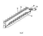
- Said receptacles 10 provided in said element 2 are distributed according to the following geometric pattern: with reference to Figure 20, said receptacles 10 are arranged along four rows, indicated at F1, F2, F3 and F4, respectively, in which they are aligned and equally spaced from each other; furthermore, each row constitutes a single group of receptacles.
- Each row extends parallel to and equidistant by a distance D from the contiguous rows, in such a manner that the totality of the rows identifies a rectangular perimeter 11, as illustrated in the Figure.
- the overall geometry defined by the totality of said receptacles 10 included in all said rows of the element 2 will be defined as "distribution pattern”.
- each row which is identical to, ie. is the same as the remaining ones, includes the highest possible number of receptacles 10 as allowed by the length of the same row, owing to reasons that will explained in a greater detail further on.
- the afore cited distance D separating contiguous rows of receptacles from each other must be equal to a multiple of the distance separating from each other the contiguous, parallel rows provided on the two opposite surfaces of the revolving turret; this is intended to make it possible for the element 2 to be able to be arranged into a plurality of distinct and selectively definable positions above said revolving turret.
- Each row of receptacles of the element 2 is therefore capable of arranging itself above a respective row of cups 6 in the revolving turret.
- the element 2 to load all of the cups provided on said revolving turret by successive cycles, while each time unloading a successive load of preforms on to a different geometry or pattern of cups by simply displacing and arranging in the proper position said element 2, so that the distribution pattern of the receptacles arranges itself exactly above successive geometries or patterns on the revolving turret.
- said means are constituted by one or more guillotine-like devices constituted by two plates 13 and 14, ie. a first plate 13, called neck centring, which has twelve perforations 15 having a diameter that is slightly larger than the diameter of the neck of the preform , and is stationary, and a second moving plate 14, constituting the actual guillotine, which has twelve buttonhole-shaped apertures having a smaller width than the diameter of the preform neck and terminating with a hole that on the contrary has a larger diameter than the preform neck.
- a first plate 13 called neck centring, which has twelve perforations 15 having a diameter that is slightly larger than the diameter of the neck of the preform , and is stationary
- a second moving plate 14 constituting the actual guillotine, which has twelve buttonhole-shaped apertures having a smaller width than the diameter of the preform neck and terminating with a hole that on the contrary has a larger diameter than the preform neck.
- the plate 13 is arranged on top and the plate 14 is arranged below; the plate 13 is stationary, whereas the plate 14 is adapted to selectively slide against said upper plate 13.
- the lower plate 14 is provided with a plurality of buttonhole-shaped apertures, each one of which is formed so as to include a first portion 16, whose cross-section is such as to enable the body of the preform, but not the neck portion thereof to pass therethrough, and a second portion 17 whose cross-section is such as to enable the whole preform to pass therethrough.
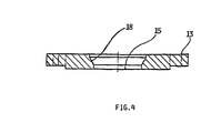
- the upper portion 18 of said perforations 15 in the upper plate 13 has an upward flared shape following a frustoconical pattern, as this is best illustrated in Figure 4.
- pairs of upper and lower plates 13 and 14 are provided and arranged in such a manner as to ensure that each such pair of plates corresponds to a same row of receptacles 10; as a result, there will be provided as many pairs of plates as said rows are.
- This turret is formed by a parallelepiped-shaped body on which there are arranged said two opposite surfaces 4 and 5, each one of which is provided with an equal number of cooling-down cups 6.
- Each preform is contained individually in elements that are usually called "cups", which must be changed whenever the type of preforms being produced is changed, since they perfectly replicate the contour of the preform.
- the cooling-down effect is obtained through the circulation of water at a low temperature around each such cup.
- the means and the techniques used to implement such a circulation are well-known to those skilled in the art.
- Each one of said surfaces 4, 5 is provided with a plurality of cups arranged in such a manner and in such a number as to make it possible for them to be gathered into a variety of distinct, but geometrically similar "distribution patterns", as better defined earlier in this description, which can be accommodated at the same time on the same surface.
- Each one of said surfaces 4 and 5 is illustrated in Figure 21, where the arrangement of the respective cups is shown.
- the described means, as well as other associated guiding, actuation, support means, or means that are anyway associated to the correct operation of the plant, and that are within the capabilities of those skilled in the art, are implemented in such a manner as to ensure that said collection element 2 is capable of moving from a position outside said structure to a plurality of selectively controlled positions located above one of said outer surfaces 4 and 5 of said revolving turret in such a manner as to enable said distribution pattern of said collection and translation element 2 to move into selectively and exactly lying above the three distinct, different distribution patterns of the cups arranged on said outer surfaces.
- the preforms that are released by said element 2 are able to fall by gravity exactly into their respective cups of a same distribution pattern thereof provided on said outer surfaces 4 and 5.
- Said revolving turret is further provided of rotation members 19 and associated devices so as to be able to be rotated by 180° about an horizontal axis thereof that passes through the centre of the parallelepiped forming the turret itself, so that the surfaces of the turret are able to exactly exchange their respective positions, upwards and/or downwards.
- the plates 13 and 14 are of course arranged in such a manner as to ensure that the aperture 15 of the plate 13 moves into a coaxial arrangement with respect to a corresponding portion 16 of the plate 14.
- the preform is facilitated in its getting inserted and centered in the respective aperture 15 in that the latter is provided with an upward flared portion 18.
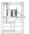
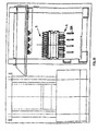
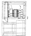
- the element 2 is displaced above the revolving turret, and namely in the position in which the distribution pattern of the element 2 lies vertically above one of the three distribution patterns provided on the outer surface 4 that is in this moment oriented upwards.
- the preforms are retained laterally by both the guillotine and the neck centring.
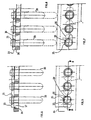
- Such a release of the preforms occurs by causing, by means of a plurality of appropriate actuators 21 illustrated in Figure 1, the lower plates 14 to slide with respect to the upper plates 13 in such a manner as to enable the apertures 15 to move into a mating correspondence with respective enlarged portions 17 of the corresponding lower plate.
- the preforms that are no longer retained by the neck portion thereof by the lower plate 14, are in this way able to fall and get exactly inserted in the respective cups 6 on the surface 4 or 5 of the revolving turret, wherein said cups are arranged exactly according to the distribution pattern on the element 2.
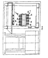
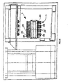
- the revolving turret is subsequently rotated by an angle of 180° about the axis X, in such a manner as to enable the preform 20A in Figure 12 to move into the position indicated at 20A in Figure 13; furthermore, during such a rotation, a second collection and insertion cycle is performed, similarly to the cycle illustrated in Figures 9 to 11, to so collect and insert a subsequent group of preforms, so that at the end of said second cycle there occurs a new insertion of preforms indicated at 20B and this situation is completely illustrated in Figure 13, with the surface 4 now being turned downwards and the surface 5 upwards.
- a third cycle of collection of preforms and rotation of the revolving turret 3 is then carried out in exactly the same manner as the preceding cycle, including the rotation of the turret 3, which therefore resumes its position with the surface 4 turned upwards, but with the difference that the element 2 is displaced into a new position, above the turret, so as to come to lie exactly above the second distribution pattern of cups provided on the same surface 4.
- This new situation is therefore illustrated in Figure 14, in which the just released preforms are indicated at 20C.
- the preforms 20A which were the first ones to be loaded in the revolving turret, are released from the latter and fall by gravity on to collection means arranged below said turret (and not shown).
- the turret rotates by a further angle of 180° so that also the preforms indicated at 20B are released therefrom, while the cups that have been cleared by the preforms 20A are now situated upwards and are so made ready to accommodate a subsequent group of preforms 20D.
- an appropriate device comprising a first plane 30 adapted to move and arrange itself between the neck portion of the preform and the respective cup, a second plane 33 carrying spring nails 31, and a pneumatic cylinder 32 actuating both said planes 30 and 33.
- this device is in the state as illustrated in Figure 23, ie. with the preform 20 that is just partially inserted in the respective cup 6, owing to any further insertion thereof being prevented by the contrast of said first plane 30 with the neck portion 40 of the preform.
- said first plane 30 and said second plane 33 are rotated and, therefore, brought close to each other by acting on said pneumatic cylinder, so that the preform is able to get fully inserted by gravity into the respective cup, as shown in Figure 24.
- said spring nails 31, which are integral with or firmly joined to said second plane 33 dispose themselves in such a manner as to come to lie upon the neck portion of the respective preforms, so as to prevent them from accidentally or untimely falling down when turned upside down.
- the second plane 33 is actuated so as to move it into arranging its spring nails 31 in a position outside and in front of the aperture of the respective preforms, so that these preforms, should it accidentally happen that they fail to be retained by the so generated vacuum when turned upside down, would in any case be retained from falling down by said spring nails 31.
- said pneumatic cylinder is operated so as to act on the afore mentioned two planes 30 and 33 with the twofold result that, on the one side, said spring nails move to a position on the side of the preforms, thereby clearing the falling trajectory thereof, and, on the other side, said first plane 30, by acting as a lever on the surface of the neck portion thereof, pushes the preforms out of the respective cups, from which they fall then down by gravity, thereby completing their ejection.
- the revolving turret is provided with the possibility for it to move upwards and/or downwards in a controlled manner.
- the necessity must in fact be considered for the outer surfaces of the turret, which must receive the preforms, to be able to be brought as close as possible to the respective receptacles of the element 2, so as to ensure an exact centring and insertion of the preforms themselves.
- these means may consist of an engagement element 42 rotatably joined to the rotating shaft of the revolving turret and capable of engaging a vertical worm screw 43 so as to be able to be actuated, upon appropriate command, so that the revolving turret can be raised and/or lowered in a manner that is fully independent of the remaining operations carried out by the plant.
Landscapes
- Engineering & Computer Science (AREA)
- Manufacturing & Machinery (AREA)
- Mechanical Engineering (AREA)
- Robotics (AREA)
- Physics & Mathematics (AREA)
- Thermal Sciences (AREA)
- Blow-Moulding Or Thermoforming Of Plastics Or The Like (AREA)
- Making Paper Articles (AREA)
- Physical Or Chemical Processes And Apparatus (AREA)
- Specific Conveyance Elements (AREA)
Claims (19)
- Anlage zur Handhabung und Abkühlung von Rohlingen, die in einer Spritzgussform erzeugt werden, wie auch die Überführung dieser Rohlinge an eine nachgeordnete Bearbeitungsstation, dadurch gekennzeichnet, dass sie besteht aus:einem bevorzugt ebenen und horizontal angeordneten Sammel- und Umsetzelement (2), das mit einer Mehrzahl von Behältern (10) versehen ist, geeignet zur Aufnahme einer entsprechenden Anzahl von Rohlingen (20), die vorzugsweise von einer Spritzgussform (4, 5) ausgestoßen wurden,einem Drehmagazinelement (3) in Form eines Parallelepipeds mit mehreren äußeren Oberflächen, die mit einer Mehrzahl von Bechern (6) versehen sind, wobei jeder von ihnen vorgesehen ist, einen entsprechenden Rohling aufzunehmen, wobei das Drehmagazin geeignet ist, in kontrollierter Weise um eine horizontale Achse (X) gedreht zu werden, um so nacheinander die mehreren äußeren Oberflächen (4, 5) nach oben und nach unten auszurichten,und dass das Sammel- und Umsetzelement (2) geeignet ist, mit einer bevorzugten translatorischen Bewegung von einer Rohling-Ladeposition zu wahlweise mehreren unterschiedlichen Positionen, die senkrecht über den genannten mehreren äußeren Oberflächen liegen, wie auch umgekehrt, verlagert zu werden, und mit Mitteln (13, 14) versehen ist, die geeignet sind, Rohlinge wahlweise in den entsprechenden Behältern (10) zu halten oder aus ihnen frei zu geben.
- Anlage nach Anspruch 1, dadurch gekennzeichnet, dass das Verteilungsmuster der Behälter (10) in dem Sammel- und Umsetzelement (2) mit dem Verteilungsmuster der Becher (6) auf den äußeren Oberflächen (4, 5) identisch ist, um so den Rohlingen zu ermöglichen, aus dem Sammel- und Umsetzelement, wenn das Letztere in einer geeigneten Position angeordnet ist, in entsprechende Becher, die in einem gleichen Verteilungsmuster auf einer Seite der äußeren Oberflächen angeordnet sind, zu fallen.
- Anlage nach Anspruch 2, dadurch gekennzeichnet, dass wenigstens eine der äußeren Oberflächen (4, 5) des Drehmagazins mit mehreren Verteilungsmustern versehen ist und jeweils Becher enthält, wobei jedes solcher Verteilungsmuster:mit dem Verteilungsmuster der Behälter (10) in dem Sammel- und Umsetzelement (2) übereinstimmt,in geeigneter Weise in Bezug auf die verbleibenden Verteilungsmuster umgesetzt wird, um so räumlich und zueinander unterschieden von allen anderen Verteilungsmustem zu sein, die auf der gleichen äußeren Oberfläche bestehen, und alle Becher der genannten mehreren Verteilungsmuster zur gleichen Zeit auf der entsprechenden äußeren Oberfläche (4, 5) angeordnet sind, ohne dass irgendwelche Becher sich gegenseitig beeinträchtigen.
- Anlage nach Anspruch 3, dadurch gekennzeichnet, dass das Sammel- und Umsetzelement geeignet ist, wahlweise in eine Mehrzahl von unterschiedlichen Positionen derartig versetzt zu werden, dass für jede dieser Positionen das Verteilungsmuster der entsprechenden Behälter exakt über einem spezifischen Verteilungsmuster der Becher zu liegen kommt, so dass die aus den Behältern frei gelassenen Rohlinge in der Lage sind, genau in die entsprechenden Becher zu fallen.
- Anlage nach Anspruch 4, dadurch gekennzeichnet, dass das Drehmagazin mit Halte- und Freigabemitteln versehen ist, um wahlweise die in die enthaltenen Becher eingesetzten Rohlinge zu halten und frei zu geben:aus einem gleichen Verteilungsmuster, undfür eine Vielzahl von Verteilungsmustern, die in einer gleichen äußeren Oberfläche (4, 5) enthalten sind, undfür eine Vielzahl von Verteilungsmustern, die in mehreren äußeren Oberflächen enthalten sind.
- Anlage nach einem der vorangegangenen Ansprüche, dadurch gekennzeichnet, dass die äußeren Oberflächen des Drehmagazins die Anzahl zwei haben und an den gegenüberliegenden parallelen Seiten des Magazins vorgesehen sind, das geeignet ist, in die zwei gegenüber liegenden Positionen wahlweise und nacheinander gedreht zu werden, die den zwei Oberflächen entsprechen, die wechselweise in die abwärts und aufwärts gerichtete Position gedreht sind.
- Anlage nach Anspruch 6, dadurch gekennzeichnet, dass das Verteilungsmuster in dem Element (2) durch eine Mehrzahl von parallelen und gleich beabstandeten (D) Reihen (F1...F4) gebildet ist, wobei jede von ihnen eine gleiche Anzahl von Behältern (10) enthält, und dass die Verteilungsmuster, die in jedem der zwei äußeren Oberflächen (4, 5) des Drehmagazins vorgesehenen sind, von einer Mehrzahl von parallelen Reihen von aufgereihten Bechern gebildet sind, die dort vorzugsweise in der durch die Größe der entsprechenden Reihe erlaubten größten Anzahl vorgesehen sind, wobei die Reihen innerhalb der Abmessungen eines Rechtecks zusammen gefasst sind, und jede von ihnen die gleiche Anzahl von Bechern enthält, wobei der Abstand zwischen einer Reihe von Bechern und deren benachbarten parallelen Reihen, die zu dem gleichen Verteilungsmuster gehören, so gewählt ist, um das Einfügen einer Mehrzahl von weiteren Reihen von Bechern zu ermöglichen, wobei jede der weiteren Reihen zu einem entsprechend unterschiedlichen Verteihmgsmuster gehört, und dass diese gleichen Verteilungsmuster so angeordnet sind, dass sie gegenseitig ineinander dringen, so dass die zu den unterschiedlichen Verteilungsmustem gehörenden Becher in einer wechselseitig alternierenden Weise entlang wenigstens einer der gleichen parallelen Reihen angeordnet sind.
- Anlage nach Anspruch 7, dadurch gekennzeichnet, dass die Verteilungsmuster von solcher Anzahl sind und in solcher Weise angeordnet sind, dass die gesamte Menge der resultierenden Becher in der Lage ist, sich selbst für jede der zwei äußeren Oberflächen anzuordnen, indem die parallelen benachbarten Reihen ein orthogonales Raster bilden, um so im wesentlichen die gesamte Fläche von jeder äußeren Oberfläche einzunehmen.
- Anlage nach einem der vorangegangenen Ansprüche, dadurch gekennzeichnet, dass die Mittel, die für ein wahlweises Halten und Freigeben der in die entsprechenden Behälter (10) eingesetzten Rohlinge vorgesehen sind, eine Guillotine-ähnliche Vorrichtung enthalten und versehen mit:einer oberen Platte (13), die fest mit dem Element (2) verbunden und mit einer Mehrzahl von Öffnungen (15) versehen ist, deren Querschnitt so ausgebildet ist, dass er dem gesamten Rohling erlaubt durch ihn hindurch zu gehen,einer unteren Platte (14), auf der eine gleiche Mehrzahl von Öffnungen vorgesehenen ist, von denen jede einen ersten Abschnitt (16) aufweist, dessen Querschnitt der Art ist, dass er dem Körper des Rohlings, jedoch nicht seinem Halsabschnitt erlaubt dort hindurch zu gehen, und einen zweiten Abschnitt (17), dessen Querschnitt im Gegensatz dazu dem gesamten Rohling ermöglicht, dort hindurch zugehen, wobei die genannte untere Platte verschiebbar beweglich in Bezug zu der oberen Platte (13) ist.
- Anlage nach Anspruch 9, dadurch gekennzeichnet, dass die Öffnungen (15) der oberen Platte (13) geeignet sind, mit dem Halsbereich des entsprechenden Rohlings in Eingriff zu kommen.
- Anlage nach Anspruch 10, dadurch gekennzeichnet, dass der äußere Bereich (18) der Öffnungen (15) der oberen Platten nach oben aufgeweitet ist.
- Anlage nach Anspruch 10 oder 11, dadurch gekennzeichnet, dass:eine lastaumehmende Vorrichtung (1) vorgesehenen ist, in Bezug zu der das Sammel- und Umsetzelement (2) verschiebbar befestigt ist und innerhalb der das Drehmagazin so angeordnet ist, dass es in der Lage ist sich zu drehen,Betätigungsmittel (21) vorgesehen sind, die mit der lastaufnehmenden Vorrichtung (1) fest verbunden und geeignet sind, auf die unteren Platten (14) so zu wirken, dass diese veranlasst werden, sich in geeigneter Weise in Bezug zu den entsprechenden oberen Platten (13) zu verschieben, so dass die in der unteren Platte vorgesehenen Öffnungen in der Lage sind, aus einer ersten Stellung, die es dem Körper, aber nicht dem Halsbereich des entsprechenden Rohlings ermöglicht, in den genannten ersten Abschnitt (16) einer entsprechenden Öffnung der unteren Platte (14) eingesetzt zu werden, in eine zweite Stellung zu bewegen, die es dem gleichen Rohling ermöglicht, in seiner Gesamtheit durch den entsprechenden zweiten Abschnitt (17) der Öffnung in der unteren Platte hindurch zu gehen.
- Anlage nach einem der vorangegangenen Ansprüche 5 bis 12, dadurch gekennzeichnet, dass die genannten Halte- und Freigabemittel des Drehmagazins eine Mehrzahl von ersten Flächen (30) enthalten, die geeignet sind, mit den Halsbereichen der entsprechenden Rohlinge in Eingriff zu kommen und sie wenigstens teilweise aus dem zugeordneten Becher zu entfernen, eine entsprechende Mehrzahl von zweiten Flächen (33), die mit einer Mehrzahl von zugeordneten Öffnungen versehen sind, die geeignet sind, das Einsetzen von entsprechenden Rohlingen in entsprechende Becher zu ermöglichen, und eine übereinstimmende Mehrzahl von Blockierungsmitteln (31), die in der Lage sind wahlweise auf den Rohlingen angeordnet zu sein, um sie am Herausgleiten aus den entsprechenden Bechern zu hindern.
- Anlage nach Anspruch 13, dadurch gekennzeichnet, dass die genannten Blockierungsmittel (31) an den genannten zweiten Flächen befestigt sind, dass dort Betätigungsmittel (32) vorgesehen und geeignet sind, die ersten und zweiten Flächen voneinander weg und / oder zueinander hin zu bewegen, und dass in der Stellung, in der diese Flächen voneinander weg bewegt sind, die entsprechenden Rohlinge an ihrem Halsbereich durch jene ersten Flächen entfernt werden, hingegen in der Stellung, in der die Flächen zueinander hin bewegt sind, jene Blockierungsmittel (31) vor der Öffnung der entsprechenden Rohlinge angeordnet sind.
- Anlage nach einem der vorangegangenen Ansprüche, dadurch gekennzeichnet, dass Mittel vorgesehen sind, die geeignet sind, wahlweise ein Vakuum innerhalb der Becher zu erzeugen, so dass die entsprechenden Rohlinge gehalten werden, wenn die Oberfläche, in der die entsprechenden Becher angeordnet sind, nach unten gedreht ist.
- Anlage nach einem der vorangegangenen Ansprüche, dadurch gekennzeichnet, dass Mittel vorgesehen sind, die geeignet sind, wahlweise einen atmosphärischen Überdruck innerhalb der Becher zu erzeugen, um so die entsprechenden Rohlinge zu lösen, wenn die Oberfläche, in der die entsprechenden Becher angeordnet sind, nach unten gedreht ist.
- Anlage nach einem der vorangegangenen Ansprüche, dadurch gekennzeichnet, dass das Drehmagazin mit Mitteln zur Abkühlung der Becher versehen ist, wobei diese Mittel vorzugsweise Kanäle enthalten, durch die ein Strom eines Kühlmittels zirkuliert wird.
- Anlage nach einem der vorangegangenen Ansprüche, dadurch gekennzeichnet, dass Mittel (42, 43) vorgesehen sind, die geeignet sind, das Drehmagazin wahlweise zu veranlassen, sich mittels einer vertikalen translatorischen Bewegung anzuheben und abzusenken.
- Anlage nach Anspruch 18, dadurch gekennzeichnet, dass dieses Hub- und Absenkmittel wenigstens ein Bauteil (42) enthält, das mit der Drehwelle des Drehmagazins in Eingriff ist, und ein Regal (43), das geeignet ist, mit dem Eingriffsmittel zusammen zu wirken.
Applications Claiming Priority (3)
| Application Number | Priority Date | Filing Date | Title |
|---|---|---|---|
| IT2000PN000006A ITPN20000006A1 (it) | 2000-01-26 | 2000-01-26 | Impianto a torre rotante su asse orizzontale per la movimentazione dipreforme |
| ITPN000006 | 2000-01-26 | ||
| PCT/EP2000/011935 WO2001054883A1 (en) | 2000-01-26 | 2000-11-29 | Horizontal-axis revolving-turret plant for handling preforms |
Publications (2)
| Publication Number | Publication Date |
|---|---|
| EP1252007A1 EP1252007A1 (de) | 2002-10-30 |
| EP1252007B1 true EP1252007B1 (de) | 2003-08-06 |
Family
ID=11453095
Family Applications (1)
| Application Number | Title | Priority Date | Filing Date |
|---|---|---|---|
| EP00981317A Expired - Lifetime EP1252007B1 (de) | 2000-01-26 | 2000-11-29 | Vorrichtung zum handhaben von vorformlingen mit einem horizontalachsigen drehturm |
Country Status (9)
| Country | Link |
|---|---|
| US (1) | US6767203B2 (de) |
| EP (1) | EP1252007B1 (de) |
| CN (1) | CN1176798C (de) |
| BR (1) | BR0017001B1 (de) |
| DE (1) | DE60004404T2 (de) |
| ES (1) | ES2204726T3 (de) |
| IT (1) | ITPN20000006A1 (de) |
| RU (1) | RU2246402C2 (de) |
| WO (1) | WO2001054883A1 (de) |
Families Citing this family (17)
| Publication number | Priority date | Publication date | Assignee | Title |
|---|---|---|---|---|
| ITPN20000036A1 (it) * | 2000-06-06 | 2001-12-06 | Sipa Spa | Impianto e procedimento per la movimentazione e raffreddamento di preforme plastiche |
| ITRM20030459A1 (it) * | 2003-10-07 | 2005-04-08 | Sipa Societa Industrializzazione P Rogettazione A | Dispositivo e processo di estrazione di oggetti in materia plastica. |
| ITRM20030461A1 (it) | 2003-10-07 | 2005-04-08 | Sipa Societa Industrializzazione P Rogettazione A | Dispositivo e processo di condizionamento di oggetti in materia plastica. |
| ITRM20030460A1 (it) * | 2003-10-07 | 2005-04-08 | Sipa Societa Industrializzazione P Rogettazione A | Dispositivo e processo di iniezione di oggetti in materia plastica. |
| ITRM20040107A1 (it) * | 2004-03-02 | 2004-06-02 | Sipa Societa Industrializzazio | Dispositivo e metodo di condizionamento di oggetti in plastica. |
| US7331777B2 (en) * | 2005-04-19 | 2008-02-19 | Owens Illinois Closure Inc. | Compression molding machine |
| US7481646B2 (en) * | 2005-06-17 | 2009-01-27 | Rexam Closure Systems Inc. | Compression molding machine |
| DE102006028725A1 (de) * | 2005-11-30 | 2007-10-18 | Mht Mold & Hotrunner Technology Ag | Verfahren und System zur Nachbehandlung von Vorformlingen |
| RU2407636C2 (ru) * | 2006-02-03 | 2010-12-27 | Индустриал Де Молдес И Матрисес, С.А. | Устройство и способ для изготовления полых корпусов, выполненных из двух материалов, посредством инжекционного многокомпонентного формования |
| RU2384411C1 (ru) * | 2008-12-18 | 2010-03-20 | Открытое Акционерное Общество "СИГОМАТИК" | Поворотная головка |
| DE102009030762B4 (de) * | 2009-06-27 | 2015-12-31 | Netstal-Maschinen Ag | Verfahren und Vorrichtung zur Herstellung von Preformen mit Spezialgeometrien |
| US20140264993A1 (en) * | 2013-03-14 | 2014-09-18 | University Of Washington Through Its Center For Commercialization | Methods for blow molding solid-state cellular thermoplastic articles |
| DE102014014144A1 (de) * | 2014-09-22 | 2016-03-24 | Mahir Aktas | Verfahren und Vorrichtung zur Herstellung einer optimierten Halskontur an Preformen |
| US11883990B2 (en) * | 2017-04-04 | 2024-01-30 | Dai Nippon Printing Co., Ltd. | Holding member, work molding system, and work molding method |
| DE102018111875A1 (de) * | 2018-05-17 | 2019-11-21 | Mht Mold & Hotrunner Technology Ag | Universalplatte |
| USD1003725S1 (en) | 2021-09-03 | 2023-11-07 | Graham Packaging Company, L.P. | Container |
| USD1010454S1 (en) | 2021-09-03 | 2024-01-09 | Graham Packaging Company, L.P. | Container |
Family Cites Families (12)
| Publication number | Priority date | Publication date | Assignee | Title |
|---|---|---|---|---|
| ZA752055B (en) * | 1974-04-16 | 1976-02-25 | Owens Illinois Inc | Method of and apparatus for blow molding plastic articles |
| FR2389479B1 (de) * | 1977-05-06 | 1980-12-12 | Carnaud Total Interplastic | |
| US4313905A (en) * | 1979-11-26 | 1982-02-02 | Hafele Robert X | Blow molding method |
| SU1399149A1 (ru) * | 1986-09-03 | 1988-05-30 | Одесское Производственное Объединение "Прессмаш" Им.60-Летия Октября | Устройство дл съема и переноса изделий на литьевой машине |
| US4721452A (en) * | 1987-03-23 | 1988-01-26 | Husky Injection Molding Systems Ltd. | Apparatus for producing hollow plastic articles |
| US4929450A (en) * | 1987-08-07 | 1990-05-29 | Toyo Seikan Kaisha, Ltd. | Delivery apparatus in machine for preparing plastic hollow vessels |
| NL9201738A (nl) * | 1992-10-08 | 1994-05-02 | Inter Tooling Services Bv | Spuitgietinrichting. |
| US5582788A (en) * | 1994-12-28 | 1996-12-10 | Continental Pet Technologies, Inc. | Method of cooling multilayer preforms |
| US5772951A (en) * | 1996-06-18 | 1998-06-30 | Husky Injection Molding Systems Ltd. | Molded article conditioning and storage system, method and resulting preform |
| US6451556B1 (en) * | 1998-12-21 | 2002-09-17 | Smithkline Beecham Corporation | EF-Tu |
| US6143225A (en) * | 1999-03-03 | 2000-11-07 | Husky Injection Molding Systems Ltd. | Turret cooling block for an index machine |
| US6223541B1 (en) * | 1999-08-17 | 2001-05-01 | Fasti, Farrag & Stipsits Gesmbh | Method and device for the after-cooling of a preform in the injection molding process |
-
2000
- 2000-01-26 IT IT2000PN000006A patent/ITPN20000006A1/it unknown
- 2000-11-29 EP EP00981317A patent/EP1252007B1/de not_active Expired - Lifetime
- 2000-11-29 ES ES00981317T patent/ES2204726T3/es not_active Expired - Lifetime
- 2000-11-29 BR BRPI0017001-1A patent/BR0017001B1/pt not_active IP Right Cessation
- 2000-11-29 RU RU2002123295/12A patent/RU2246402C2/ru active
- 2000-11-29 US US10/181,032 patent/US6767203B2/en not_active Expired - Lifetime
- 2000-11-29 DE DE60004404T patent/DE60004404T2/de not_active Expired - Lifetime
- 2000-11-29 CN CNB008186235A patent/CN1176798C/zh not_active Expired - Fee Related
- 2000-11-29 WO PCT/EP2000/011935 patent/WO2001054883A1/en not_active Ceased
Also Published As
| Publication number | Publication date |
|---|---|
| RU2246402C2 (ru) | 2005-02-20 |
| DE60004404T2 (de) | 2005-06-23 |
| ITPN20000006A1 (it) | 2001-07-26 |
| WO2001054883A1 (en) | 2001-08-02 |
| US6767203B2 (en) | 2004-07-27 |
| RU2002123295A (ru) | 2004-02-20 |
| ES2204726T3 (es) | 2004-05-01 |
| CN1424960A (zh) | 2003-06-18 |
| DE60004404D1 (de) | 2003-09-11 |
| CN1176798C (zh) | 2004-11-24 |
| BR0017001A (pt) | 2002-10-15 |
| BR0017001B1 (pt) | 2009-08-11 |
| EP1252007A1 (de) | 2002-10-30 |
| US20030003187A1 (en) | 2003-01-02 |
Similar Documents
| Publication | Publication Date | Title |
|---|---|---|
| US6767203B2 (en) | Horizontal-axis revolving-turret plant for handling preforms | |
| USRE33237E (en) | Apparatus for producing hollow plastic articles | |
| CA1287958C (en) | Apparatus for reducing hollow plastic articles | |
| JP4658942B2 (ja) | プラスチック製物体用射出成形装置及び方法 | |
| US3990826A (en) | Injection blow molding apparatus | |
| EP2361745A2 (de) | Kontinuierliche Formungsmaschine | |
| EP1673209B1 (de) | Vorrichtung und verfahren zum extrahieren von kunststoffgegenständen | |
| EP1701832B1 (de) | Konditioniervorrichtung für kunststoffgegenstände und verfahren | |
| EP1286817B1 (de) | Vorrichtung und verfahren zum handhaben und zur kühlung von kunststoffvorformlingen | |
| EP2396161B1 (de) | Verbessertes spritzgiessen und kühlung von kunststoffartikeln | |
| KR101210160B1 (ko) | 플라스틱 물품의 성형 | |
| RU2358868C2 (ru) | Устройство и способ для приведения пластиковых объектов в требуемое состояние | |
| MXPA06004001A (en) | Device and process for extracting plastic items | |
| MXPA06004000A (en) | Conditioning device for plastic items and process |
Legal Events
| Date | Code | Title | Description |
|---|---|---|---|
| PUAI | Public reference made under article 153(3) epc to a published international application that has entered the european phase |
Free format text: ORIGINAL CODE: 0009012 |
|
| 17P | Request for examination filed |
Effective date: 20020604 |
|
| AK | Designated contracting states |
Kind code of ref document: A1 Designated state(s): AT BE CH CY DE DK ES FI FR GB GR IE IT LI LU MC NL PT SE TR |
|
| GRAH | Despatch of communication of intention to grant a patent |
Free format text: ORIGINAL CODE: EPIDOS IGRA |
|
| GRAH | Despatch of communication of intention to grant a patent |
Free format text: ORIGINAL CODE: EPIDOS IGRA |
|
| GRAA | (expected) grant |
Free format text: ORIGINAL CODE: 0009210 |
|
| AK | Designated contracting states |
Designated state(s): DE ES FR GB IT LU |
|
| REG | Reference to a national code |
Ref country code: GB Ref legal event code: FG4D |
|
| REG | Reference to a national code |
Ref country code: IE Ref legal event code: FG4D |
|
| REF | Corresponds to: |
Ref document number: 60004404 Country of ref document: DE Date of ref document: 20030911 Kind code of ref document: P |
|
| ET | Fr: translation filed | ||
| REG | Reference to a national code |
Ref country code: ES Ref legal event code: FG2A Ref document number: 2204726 Country of ref document: ES Kind code of ref document: T3 |
|
| PLBE | No opposition filed within time limit |
Free format text: ORIGINAL CODE: 0009261 |
|
| STAA | Information on the status of an ep patent application or granted ep patent |
Free format text: STATUS: NO OPPOSITION FILED WITHIN TIME LIMIT |
|
| 26N | No opposition filed |
Effective date: 20040507 |
|
| REG | Reference to a national code |
Ref country code: IE Ref legal event code: MM4A |
|
| PG25 | Lapsed in a contracting state [announced via postgrant information from national office to epo] |
Ref country code: IT Free format text: LAPSE BECAUSE OF NON-PAYMENT OF DUE FEES Effective date: 20081129 |
|
| PGRI | Patent reinstated in contracting state [announced from national office to epo] |
Ref country code: IT Effective date: 20110616 |
|
| REG | Reference to a national code |
Ref country code: FR Ref legal event code: PLFP Year of fee payment: 15 |
|
| PGFP | Annual fee paid to national office [announced via postgrant information from national office to epo] |
Ref country code: ES Payment date: 20150227 Year of fee payment: 15 |
|
| PGFP | Annual fee paid to national office [announced via postgrant information from national office to epo] |
Ref country code: FR Payment date: 20150309 Year of fee payment: 15 Ref country code: GB Payment date: 20150225 Year of fee payment: 15 |
|
| GBPC | Gb: european patent ceased through non-payment of renewal fee |
Effective date: 20151129 |
|
| REG | Reference to a national code |
Ref country code: FR Ref legal event code: ST Effective date: 20160729 |
|
| PG25 | Lapsed in a contracting state [announced via postgrant information from national office to epo] |
Ref country code: GB Free format text: LAPSE BECAUSE OF NON-PAYMENT OF DUE FEES Effective date: 20151129 |
|
| PG25 | Lapsed in a contracting state [announced via postgrant information from national office to epo] |
Ref country code: FR Free format text: LAPSE BECAUSE OF NON-PAYMENT OF DUE FEES Effective date: 20151130 |
|
| REG | Reference to a national code |
Ref country code: ES Ref legal event code: FD2A Effective date: 20161227 |
|
| PG25 | Lapsed in a contracting state [announced via postgrant information from national office to epo] |
Ref country code: ES Free format text: LAPSE BECAUSE OF NON-PAYMENT OF DUE FEES Effective date: 20151130 |
|
| PGFP | Annual fee paid to national office [announced via postgrant information from national office to epo] |
Ref country code: LU Payment date: 20181126 Year of fee payment: 19 |
|
| PGFP | Annual fee paid to national office [announced via postgrant information from national office to epo] |
Ref country code: DE Payment date: 20181113 Year of fee payment: 19 |
|
| PGFP | Annual fee paid to national office [announced via postgrant information from national office to epo] |
Ref country code: IT Payment date: 20181120 Year of fee payment: 19 |
|
| REG | Reference to a national code |
Ref country code: DE Ref legal event code: R119 Ref document number: 60004404 Country of ref document: DE |
|
| PG25 | Lapsed in a contracting state [announced via postgrant information from national office to epo] |
Ref country code: LU Free format text: LAPSE BECAUSE OF NON-PAYMENT OF DUE FEES Effective date: 20191129 |
|
| PG25 | Lapsed in a contracting state [announced via postgrant information from national office to epo] |
Ref country code: IT Free format text: LAPSE BECAUSE OF NON-PAYMENT OF DUE FEES Effective date: 20191129 Ref country code: DE Free format text: LAPSE BECAUSE OF FAILURE TO SUBMIT A TRANSLATION OF THE DESCRIPTION OR TO PAY THE FEE WITHIN THE PRESCRIBED TIME-LIMIT Effective date: 20200603 |