EP1251367A1 - Umlenkspiegelstruktur, bestehend aus einer Vielzahl von Tripeln - Google Patents
Umlenkspiegelstruktur, bestehend aus einer Vielzahl von Tripeln Download PDFInfo
- Publication number
- EP1251367A1 EP1251367A1 EP02008527A EP02008527A EP1251367A1 EP 1251367 A1 EP1251367 A1 EP 1251367A1 EP 02008527 A EP02008527 A EP 02008527A EP 02008527 A EP02008527 A EP 02008527A EP 1251367 A1 EP1251367 A1 EP 1251367A1
- Authority
- EP
- European Patent Office
- Prior art keywords
- triples
- light
- mirror
- triple
- mirror surfaces
- Prior art date
- Legal status (The legal status is an assumption and is not a legal conclusion. Google has not performed a legal analysis and makes no representation as to the accuracy of the status listed.)
- Granted
Links
- 239000002245 particle Substances 0.000 claims description 6
- 229910052751 metal Inorganic materials 0.000 claims description 5
- 239000002184 metal Substances 0.000 claims description 5
- 239000004033 plastic Substances 0.000 claims description 5
- 229920003023 plastic Polymers 0.000 claims description 5
- PXHVJJICTQNCMI-UHFFFAOYSA-N Nickel Chemical compound [Ni] PXHVJJICTQNCMI-UHFFFAOYSA-N 0.000 claims description 4
- 239000011521 glass Substances 0.000 claims description 3
- 239000000463 material Substances 0.000 claims description 3
- 239000005304 optical glass Substances 0.000 claims description 3
- 239000005388 borosilicate glass Substances 0.000 claims description 2
- 229910052759 nickel Inorganic materials 0.000 claims description 2
- 229920003229 poly(methyl methacrylate) Polymers 0.000 claims 2
- 239000004926 polymethyl methacrylate Substances 0.000 claims 2
- 229910001369 Brass Inorganic materials 0.000 claims 1
- 229910000906 Bronze Inorganic materials 0.000 claims 1
- RYGMFSIKBFXOCR-UHFFFAOYSA-N Copper Chemical compound [Cu] RYGMFSIKBFXOCR-UHFFFAOYSA-N 0.000 claims 1
- VYPSYNLAJGMNEJ-UHFFFAOYSA-N Silicium dioxide Chemical compound O=[Si]=O VYPSYNLAJGMNEJ-UHFFFAOYSA-N 0.000 claims 1
- BQCADISMDOOEFD-UHFFFAOYSA-N Silver Chemical compound [Ag] BQCADISMDOOEFD-UHFFFAOYSA-N 0.000 claims 1
- 229910000831 Steel Inorganic materials 0.000 claims 1
- RTAQQCXQSZGOHL-UHFFFAOYSA-N Titanium Chemical compound [Ti] RTAQQCXQSZGOHL-UHFFFAOYSA-N 0.000 claims 1
- 229910052782 aluminium Inorganic materials 0.000 claims 1
- XAGFODPZIPBFFR-UHFFFAOYSA-N aluminium Chemical compound [Al] XAGFODPZIPBFFR-UHFFFAOYSA-N 0.000 claims 1
- 239000010951 brass Substances 0.000 claims 1
- 239000010974 bronze Substances 0.000 claims 1
- 229910052802 copper Inorganic materials 0.000 claims 1
- 239000010949 copper Substances 0.000 claims 1
- KUNSUQLRTQLHQQ-UHFFFAOYSA-N copper tin Chemical compound [Cu].[Sn] KUNSUQLRTQLHQQ-UHFFFAOYSA-N 0.000 claims 1
- 239000005329 float glass Substances 0.000 claims 1
- PCHJSUWPFVWCPO-UHFFFAOYSA-N gold Chemical compound [Au] PCHJSUWPFVWCPO-UHFFFAOYSA-N 0.000 claims 1
- 229910052737 gold Inorganic materials 0.000 claims 1
- 239000010931 gold Substances 0.000 claims 1
- 239000011133 lead Substances 0.000 claims 1
- MOFOBJHOKRNACT-UHFFFAOYSA-N nickel silver Chemical compound [Ni].[Ag] MOFOBJHOKRNACT-UHFFFAOYSA-N 0.000 claims 1
- 239000010956 nickel silver Substances 0.000 claims 1
- 239000004417 polycarbonate Substances 0.000 claims 1
- 229920000515 polycarbonate Polymers 0.000 claims 1
- 239000004800 polyvinyl chloride Substances 0.000 claims 1
- 238000007493 shaping process Methods 0.000 claims 1
- 229910052709 silver Inorganic materials 0.000 claims 1
- 239000004332 silver Substances 0.000 claims 1
- 238000004544 sputter deposition Methods 0.000 claims 1
- 239000010959 steel Substances 0.000 claims 1
- 239000010936 titanium Substances 0.000 claims 1
- 229910052719 titanium Inorganic materials 0.000 claims 1
- 238000007740 vapor deposition Methods 0.000 claims 1
- 230000001788 irregular Effects 0.000 abstract 1
- 238000004519 manufacturing process Methods 0.000 description 11
- 238000005516 engineering process Methods 0.000 description 9
- 230000004888 barrier function Effects 0.000 description 7
- 230000003287 optical effect Effects 0.000 description 6
- 230000000694 effects Effects 0.000 description 5
- 238000000034 method Methods 0.000 description 4
- 238000012544 monitoring process Methods 0.000 description 4
- 230000008859 change Effects 0.000 description 3
- 238000005259 measurement Methods 0.000 description 3
- 230000008569 process Effects 0.000 description 2
- 239000000779 smoke Substances 0.000 description 2
- 210000004127 vitreous body Anatomy 0.000 description 2
- 230000005540 biological transmission Effects 0.000 description 1
- 210000004556 brain Anatomy 0.000 description 1
- 230000006835 compression Effects 0.000 description 1
- 238000007906 compression Methods 0.000 description 1
- 230000001419 dependent effect Effects 0.000 description 1
- 238000013461 design Methods 0.000 description 1
- 230000007613 environmental effect Effects 0.000 description 1
- 238000002474 experimental method Methods 0.000 description 1
- 239000011888 foil Substances 0.000 description 1
- 238000010438 heat treatment Methods 0.000 description 1
- 238000001746 injection moulding Methods 0.000 description 1
- 230000002452 interceptive effect Effects 0.000 description 1
- 238000012986 modification Methods 0.000 description 1
- 230000004048 modification Effects 0.000 description 1
- 238000000465 moulding Methods 0.000 description 1
- 238000005025 nuclear technology Methods 0.000 description 1
- 230000001953 sensory effect Effects 0.000 description 1
- 230000035939 shock Effects 0.000 description 1
- 230000011664 signaling Effects 0.000 description 1
- 238000004088 simulation Methods 0.000 description 1
- 238000012360 testing method Methods 0.000 description 1
- 239000004753 textile Substances 0.000 description 1
Images


Classifications
-
- G—PHYSICS
- G02—OPTICS
- G02B—OPTICAL ELEMENTS, SYSTEMS OR APPARATUS
- G02B5/00—Optical elements other than lenses
- G02B5/12—Reflex reflectors
- G02B5/122—Reflex reflectors cube corner, trihedral or triple reflector type
- G02B5/124—Reflex reflectors cube corner, trihedral or triple reflector type plural reflecting elements forming part of a unitary plate or sheet
Definitions
- the invention relates to a deflecting mirror structure based on a Variety of micro triplets based, their smallest edge length is less than 2.1 mm.
- the aim of this deflecting mirror structure is to be one of a light transmitter to reflect incident light to another point in the room.
- the angular alignment of the light transmitter for the Practice allow an angular tolerance so that the assembly and Application of the deflecting mirror structure compared to the Use a conventional plane mirror or Deflection prism is facilitated.
- this Deflecting mirror structure because of its easy handling suitable because it is particularly simple for the beam path of the redirectable light beam.
- the deflecting mirror structure solves practical alignment problems and enables new applications in light sensor technology in which Laser sensors, laser beam guidance and in security technology of road traffic to redirect light and to beam or Elementary particle deflection in nuclear technology.
- the innovative deflecting mirror structure consisting of a multitude of triples, enables optical sensors behind edges and To look at corners, to create light grids, in narrow spaces like Pipes or ball bearings to perform measurement tasks, rotations and to observe twists in fire protection rooms Monitor fire or smoke.
- Can in traffic retroflective structures obtained through wide-angle properties Add triples to the deflecting mirror structure.
- the Beam splitting or redirection of elementary particles is a Area of responsibility of the deflecting mirror structure.
- DE 44 10 994 describes bodies and / or components a strand-shaped triple reflector and / or tool element for molding triple reflectors with full cube properties. These strand-shaped components can also be particularly easily In microstructure technology, they join together and are a manufacturing technique that is also used for the production of molded articles or representation of the deflecting mirror structure according to the invention suitable is.
- the deflecting mirror structure according to the invention is based on Production on the known processes for the production of Triple reflectors.
- the description here is based on especially on triples that come close to the Fullcube.
- triples that come close to the Fullcube.
- the modification of the full cube Preference should be given because it is fundamentally essential has less scatter loss than the pyramid.
- the pyramid as Triple is preferable when mechanical manufacturing very small triple required, because pyramidal triple structures can be cut from a flat common surface, on the other hand, full-cube triples in tool making need that Arrangement of a variety of components to large to represent structured surfaces from a multitude of triples.
- the manufacturing methods and their advantages and disadvantages in the Production of triples are known to the person skilled in the art and need not be repeated here.
- the invention makes use of the experience gained in the manufacture and use of Fulicube triples in technology.
- the full-cube triple has the excellent property of receiving incident light within a wide tolerance range of the angle of incidence and retroflecting it almost completely to the light source.
- the retroflexion takes place via the reflection of light on the three square surfaces of the full-cube triple.
- This angle tolerance for the incident light is used in practical use with most retro-reflective sensors today.
- the assembly and alignment of the reflectors at an angle to the transmitter / receiver system is simple and fault-tolerant. Beam movements due to vibrations are usually tolerated by this reflection element with full-cube triples.
- the invention proposes a deflecting mirror structure consisting of a large number of triples. These triples differ from retroflexion triples in considerable detail. Not all mirror sides of the triple used are at right angles to each other, as is required for retroflexion.
- the deflecting mirror structure uses a triple ( FIG. 1) formed from three mirror surfaces (1, 2, 3) or ( FIG. 2) the mirror surfaces (1, 2, 5), the mirror surface (2) being related to the mirror surface ( 1) is at an opening angle significantly greater than 90 °.
- a triple with an apparently incorrectly arranged mirror surface would no longer be able to function as a retroflexion element. Because the incident light beam is divided into three light beams. In the case of triple structures which are designed as vitreous bodies, further beam paths arise which need not be considered here. Now that the mirror surface (2) has been turned over the common edge to the mirror surface (1), it is stretched at the same time.
- the extension of the mirror surface (2) does more Mirror surface is available on which there are reference points find for the ray paths by the other two Mirror surfaces come. Even when the beam paths are reversed, if the light beam arriving from the transmitter first Mirror surface (2) hits, more capture area is available with possible reference points of the beam paths to the two other mirror surfaces.
- the mirror side (3) in FIG. 1 and the corresponding mirror side (5) in FIG. 2 are enlarged by a square. With these measures, the intensity of the three beams that leave the triple according to the invention is changed considerably in relation to one another.
- FIGS. 11 and 12 show the resulting light path.
- the major part of the light beam is deflected in the spatial direction (22).
- the light beam (24) falls at an angle, the major part of the light beam is deflected perpendicularly (27) to the light entry surface in the spatial direction (26).
- the lost part of the light beam which does not participate in the intended deflection, is reflected to a small extent and partly reflected in the opposite direction of loss to the spatial direction (22), the plumb line (27) corresponding to the line around which the spatial direction ( 22) is mirrored to the direction of loss.
- this deflecting mirror structure on the one hand, some light is lost, but the angular tolerance is obtained for two incident beam positions (22) and (24).
- the axis position of the triple in Reference to the light entry surface can of course be varied so that the beam paths for the deflection can be changed for both the angle of the incoming light beam as well as for the Angle of the deflected light beam in relation to the Light entry surface or perpendicular to the light entry surface fell.
- microtrips the smallest of which Edge length is ⁇ 2.1 mm.
- microtriples show another much greater angular tolerance compared to the incident Bundle of light as a conventional macrotripel.
- microtriples provide significantly higher luminous efficacy than conventional ones Makrotripel.
- deflecting mirror structure In the deflecting mirror structure according to the invention, two basic functions can be distinguished.
- an exemplary structure as in FIG. 3 composed of triples of FIG. 1, which deflects the incident light beam in two spatial directions, as shown in FIG. 20, because almost no light is lost in the process.
- the deflecting mirror structure is because of its tolerance towards the angle of the incident light beam very easily handle and manufacture for the desired deflection. Becomes the surface (2) of the triple is only rotated by about 8 ° so that it is in Reference to surface (1) has an opening angle of 98 °, see above can already have a deflecting effect of the deflecting mirror structure from about 30 ° to 35 ° can be achieved in relation to the angle incident light beam.
- the possible deflection angles are from the material properties and surface of the Deflecting mirror structure dependent. For glass bodies, plastic bodies or for metal bodies or bodies with metallized Surface deflection properties differ slightly by +/- 7 °.
- Fig. 1 shows a single triple of the deflecting mirror structure, according to claim 1.
- the triple consists of three mirror surfaces (1, 2, 3), of which the two mirror surfaces (1 and 3) and the two mirror surfaces (2 and 3) to each other at a right angle stand.
- the shape of the mirror surface (3) which is an uneven square, is striking.
- An essential feature of the triple is that the two mirror surfaces (1 and 2) are arranged at an angle greater than 90 ° to one another.
- the center of the triple is the lowest point (4) that all three mirror surfaces touch.
- the base of the triple projected onto a plane is an uneven hexagon.
- the shape of the triple is such that it can be combined with other triples of the same type to form a deflecting mirror structure ( FIGS. 3 and 4) which can deflect the incident light in two different directions and acts like a beam splitter.
- Fig. 2 shows a single triple of the deflecting mirror structure, according to claim 2.
- the triple consists of three mirror surfaces (1, 2, 5), of which the two mirror surfaces (1 and 5) and the two mirror surfaces (2 and 5) to each other at right angles stand.
- the shape of the mirror surfaces (2 and 5), which are each an elongated rectangle, is striking.
- An essential feature of this triple is that the two mirror surfaces (1 and 2) are arranged at an angle greater than 90 ° to one another.
- the center of the triple is the lowest point (4).
- the base of the triple projected onto a plane is an uneven hexagon.
- the shape of the triple is such that it forms one with other similar triples Deflecting mirror structure ( Fig. 7 and Fig. 8) can be added, which can mainly deflect the incident light in one direction.
- Fig. 3 is a deflecting mirror structure, which is assembled from triplets of Fig. 1.
- the perspective view means that the mirror surfaces (2 and 7) of Fig. 4 are not visible.
- the mirror surfaces (1) and (3) show the triples of the first orientation.
- the mirror surfaces (6) and (8) show the triple of the second orientation in its position rotated by 180 ° relative to the triple of the first orientation.
- the triples of the same orientation are arranged in rows. Rows with opposite directions alternate.
- the orientation of the triple (Fig. 11) determines the spatial direction to which it deflects the incident light or from which it should receive light.
- Fig. 4 shows the deflecting mirror structure of Fig. 3 in the view from above and thus the projection of all edges onto a base.
- the mirror surfaces (1, 2, 3) which are arranged around the triple center (4) form the triple of the first orientation, Fig. 6 (9).
- the mirror surfaces (6, 7, 8) which are arranged around the triple center (4) form the triple of the opposite second orientation, Fig. 6 (10).
- Fig. 5 is a section through the Umlenkapt für Fig. 4. The section goes through the opposing Tripel whatsoever.
- Fig. 6 rotated the deflecting mirror structure in space so that all mirror surfaces (3) of the triple of the first orientation (9) with the mirror surfaces (8) of the triple of the second orientation (10) show a closed-acting surface. It is clear here that the deflecting mirror structure can be seamlessly assembled from the triples of FIG. 1.
- Fig. 7 shows the deflecting mirror structure according to claim 2, which is assembled from triplets of Fig. 2. Due to the perspective view, a mirror surface (12) of FIG. 8 is not visible in each case.
- Fig. 8 is the same Umlenkapt für FIG. 7 in a view from above, and thus the projection of all edges on a base surface. All mirror surfaces of the triples are rectangles. The mirror surfaces (11, 12, 13) are arranged around the triple center (14). All triples are evenly aligned and therefore mostly only redirect the light in one spatial direction.
- Fig. 9 shows the section through the Umlenkapt für of FIG. 8. The section goes through all arranged in the same orientation triplet.
- Fig. 10 the deflecting mirror structure of Fig. 7 rotated in space so that all mirror surfaces (13) of the triple of the same orientation (15) show a closed-acting surface.
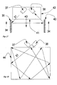
- Fig. 11 illustrates the functional principle of Umlenkapt für Heidelberg Druck and shows the comparison to a Retroflexionstripel, the triple is simplified as shown with considerably exaggerated angles to the operation to make two-dimensional optical glass body visible. On the other hand, in practice, even small changes in angle are very effective, but not clearly visible in the drawing.
- the optical glass body has the optical axis (27), which here in In this example, the plumb bob falls on the light entry side (16).
- the optical axis can also deviate from Lot (27) lie when the triple is in its position accordingly Light entry side (16) is changed.
- the line (17) represents in this example, the mirror surfaces designated in Fig. 1 as (1) and (3) designated mirror surfaces, and in Fig. 2 as (1) and (5), which are mutually at right angles.
- the dashed line (18) marks the position of an imaginary third mirror surface, which is at right angles to the other two mirror surfaces.
- This design would correspond to a retroflexion mirror in which all three mirror surfaces of the triple are at right angles to each other.
- the light bundle (20) emitted by a light transmitter enters the light entry side of the vitreous body, is deflected via the mirror surfaces of the retroflexion triple and exits again as a light bundle (23) in order to return in the spatial direction of the light transmitter.
- a beam offset occurs between the beam path of the incoming light bundle (20) and the emerging light bundle (23), which is determined by the size of the retroflexion triple.
- the mirror surface (18) is now replaced by the mirror surface (19), which is designated in FIG. 1 as a mirror surface (2) and in FIG. 2 also as a mirror surface (2). That is, the mirror surface (18) is rotated about the axis, the axis of rotation is given by the common edge of the mirror surfaces (1) and (2) of Fig. 1 and Fig. 2, and at the same time, the rectangle of the mirror surface (2 ) stretched so that the angle between the mirror surface (1) and (2) is greater than 90 °.
- the mirror surface (2) is at right angles to the mirror surface (3) in FIG. 1 , but at an angle greater than 90 ° to the mirror surface (1).
- the mirror surface (2) is at right angles to the mirror surface (5) in FIG.
- the mirror surface (2) from FIGS. 1 and 2 is identified here as (19).
- the light beam (20) emitted by a light transmitter enters the triple surface, the light entrance side of the triple, and is first reflected as a beam (21) and then deflected in the spatial direction (22) via the mirror side (19).
- the beam of rays does not now return to the light transmitter, but is deflected.
- Fig. 12 the same triple as Fig. 11, but the direction of the beam path of the light beam is now reversed.
- the beam of light (24) is emitted by the light transmitter, which, contrary to the plumb line (27), enters the light entry side (16) at an angle, then is deflected above the mirror surface (19) to position (17), which defines the playing surfaces (1) and (3 ) in Fig. 1 or (1) and (5) in Fig. 2 , and finally leaves the triple as a beam (26).
- the one-sided deflecting mirror structure is selected as an example, which is assembled from triplets of FIG. 2 and whose beam paths are easier to display.
- the transmitter (28) which emits any light or laser light or reflectable elementary particles, sends its beam (31) onto the deflecting mirror structure (29). This is aligned in direction (30).
- the beam (31) is deflected and thrown onto the receiver (32).
- This receiver can now evaluate the signal, for example as a light barrier.
- (32) can also be a retroflection element which reflects the light beam (31) in the same way, so that it returns at the transmitter.
- the transmitter could then also be a receiver, as is the case with a retro-reflective sensor, for example.
- Fig. 14 this path of the light beam (31) as it returns as a light beam (35) to the transmitter / receiver.
- the light beam is deflected several times via two opposite deflecting mirror structures (29) and (33).
- the deflecting mirror structures are arranged in opposite directions (30) and (34). This creates a light grid in the space between (29) and (33).
- This light curtain can monitor, for example on a plastic injection molding machine, whether a plastic part falls through.
- the deflecting mirror structure according to the invention thus makes it possible to create a light grid for security monitoring with little electronic outlay. So far, this could only be solved in a complex manner by arranging many light barriers arranged one below the other,
- Fig. 15 is now a special monitoring capability for the use of a light barrier or another optical measuring system. Often there is no space on machines to mount light barriers. In the textile industry, it is difficult to look behind the thread spools with the light beam to monitor the thread breakage.
- the problem can be solved with the deflecting mirror structure according to the invention. It can also be used to monitor the inside of a tube (36) from the outside.
- the transmitter / receiver sends the beam (31) onto the deflecting mirror structure (29), from there it is thrown onto the retroflector (32) and then returns in the same way to the transmitter / receiver, which is arranged outside the exemplary tube.
- FIG. 15 is also an application demonstration for a technically particularly difficult measurement task. If, for example, the rotation or twisting is to be monitored within a ball bearing, the measuring electronics can be positioned outside the ball bearing, while inside the ball bearing (36) the deflecting mirror structure (29) is arranged with a second or a retroflexion mirror (32) as in this figure illustrated. 15,.
- the Umlenkapt minimalist (29) can also be such that the angle of the incident and of the emergent light beam may be determined differently than shown in the previous examples is intended to illustrate.
- the deflecting mirror structure is assembled from the triples according to the invention in such a way that the axes of the triples are changed in their position.
- Fig. 17 shows an application that is particularly suitable for roller doors that come from above.
- the light barrier system is attached to the movable roller door.
- Long bands (39) and (40) from the deflecting mirror structure according to the invention are arranged in the orientation (34) on the sides of the gate.
- the light beam (31) is deflected to the receiver via the bands (39) and (40). This beam of light thus runs horizontally between the two bands and lies below the door edge (41) of the roller shutter (42), which lowers in the direction (43).
- Fig. 18 a transmitter (37) and a receiver (38) which are to monitor the room (44) with the light beam (31) as a smoke detector.
- the light beam can take a desired path through the room.
- Fig. 19 shows an example of the road traffic.
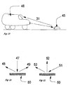
- Marking buttons (45) on the streets that retroflect have to solve the problem of making the light beam (31) of the motor vehicle headlights visible to the driver sitting much higher in trucks (46) via retroflexion.
- Retro reflectors send the light back directly to the light source. If these triplets according to the invention of FIG. 2 are also added to these retroflexion elements, which mostly consist of triple structures, the light beam of the headlights can also be deflected to the driver's eye.
- the reflective area of the marking button (45) is thereby expanded.
- Fig. 20 the function of the Umlenkapt für Fig. 3, which is composed of triplets according to the invention FIG. 1.
- the light bundle (47) is sent to the deflecting mirror structure (50) and there divided into two light bundles (48) and (49) which leave the deflecting mirror structure (50) in opposite directions.
- This effect of a beam splitter in combination with the elements and arrangements presented so far enables even more complex light grids and monitoring tasks in light sensor systems.
- this structure for example made of nickel or lead, can be used as a beam splitter or baffle, so that the elementary particles hitting the front are deflected to the sides.
- FIG. 21 shows the same deflecting mirror structure as FIG. 20, but the light bundle is sent obliquely from the spatial direction (51) onto the structure and deflected to the spatial directions (52) and (53).
- the deflecting mirror structure works like a beam splitter, so that the two outgoing beams can be received and evaluated by two different measuring systems.
- a retroflector can be arranged on one or the two spatial directions of the light beams emanating from the deflecting mirror structure, so that the light beams return accordingly to the transmitter / receiver or to one direction.
- the deflecting mirror structure according to the invention can also be closed large areas on signs or on tapes or foils to be ordered. You can also do easier tasks in the Lighting technology, for example for backlighting used by LCD displays or for better Light distribution of lighting fixtures in the room.
- this deflecting mirror structure is an excellent sensory element for signaling minor changes such as heat, shock, compression, twisting and all types of minimal deformation.
- any change in the shaft can be optically queried via the change in the deflecting property of the deflecting mirror structure. This can be explained from the angular situation of the new type of triple used. Even a slight change in the angle of the mirror side (3) in relation to the mirror surface (1) causes a much higher deflection of the triple according to the invention. If the light beam is run above many deflecting mirror structures, the property of the overall system as a sensor with a sensor effect is enhanced.
Landscapes
- Physics & Mathematics (AREA)
- General Physics & Mathematics (AREA)
- Optics & Photonics (AREA)
- Optical Elements Other Than Lenses (AREA)
- Mechanical Light Control Or Optical Switches (AREA)
- Aerials With Secondary Devices (AREA)
- Optical Communication System (AREA)
Abstract
Description
ermöglicht Lichtbündel mittels der Anordnung von Spiegeln oder Prismen umzulenken. Jedoch im praktischen Einsatz bei der Montage an einer Maschine zeigen sich größte Schwierigkeiten, diese Spiegel oder Prismen so anzubringen und schnell auszurichten, dass der gewünschte Strahlverlauf erreicht wird. Nur wer es selbst einmal versucht hat, ein nicht sichtbares Lichtbündel eines Sensors über mehrere Umlenkungen zu führen, weiß wie mühevoll es ist. Denn es bedarf einer langen Übungszeit und Lemphase des menschlichen Gehirns, Winkel und Strahlverläufe richtig einzuschätzen aus der Position des Beobachters, der mit seinen Augen nicht selbst im Strahlengang steht.
Die Schwierigkeiten nehmen aber noch zu, wenn der Maschinenkörper, zum Beispiel eine Förderanlage, vibriert. Ein Laserstrahlbündel tanzt dann durch die Vibration über den Planspiel und der Strahlverlauf über mehrere Umlenkungen verändert sich erheblich. Meist wird dann einer der Zielpunkte nicht mehr erreicht.
schlägt eine Umlenkspiegelstruktur vor, die aus einer Vielzahl von Tripeln besteht. Diese Tripel unterscheiden sich zu Retroflexionstripeln in einem erheblichen Detail. Nicht alle Spiegelseiten des verwendeten Tripels stehen zueinander im Rechten Winkel, wie es bei der Retroflexion erforderlich ist.
Die Umlenkspiegelstruktur verwendet als Kemelement einen Tripel (Fig. 1) gebildet aus drei Spiegelflächen (1, 2, 3) oder (Fig. 2) die Spiegelflächen (1, 2, 5), wobei die Spiegelfläche (2) im Bezug zur Spiegelfläche (1) in einem Öffnungswinkel deutlich größer 90° steht.
Als Retroflexionselement wäre so ein Tripel mit einer scheinbaren fehlerhaft angeordneten Spiegelfläche nicht mehr funktionsfähig. Denn das einfallende Lichtbündel wird in drei Lichtbündel aufgeteilt. Bei Tripelstrukturen, die als Glaskörper ausgebildet sind, entstehen noch weitere Strahlengänge, die hier nicht betrachtet werden brauchen.
Nachdem nun die Spiegelfläche (2) über die gemeinsame Kante zur Spiegelfläche (1) gedreht wurde, wird sie zugleich gestreckt.
Mit dieser Umlenkspiegelstruktur geht also zum einen etwas Licht verloren, dafür wird aber die Winkeltoleranz gewonnen für zwei einfallende Strahlpositionen (22) und (24).
Zum einen eine beispielhafte Struktur wie in Fig. 3 aus Tripeln der Fig. 1 zusammengefügt, die das einfallende Lichtbündel nach zwei Raumrichtungen umlenkt, wie in Fig. 20 gezeigt, denn dabei geht nahezu kein Licht verloren.
Zum anderen eine Umlenkspiegelstruktur wie beispielhaft in Fig. 7 gezeigt, die aus Tripeln der Fig. 2 zusammengefügt ist und das Licht überwiegend in eine Raumrichtung umlenkt, wie in Fig. 11 und 12 gezeigt.
Fig. 1 einen einzelnen Tripel der Umlenkspiegelstruktur, nach Anspruch 1. Der Tripel besteht aus drei Spiegelflächen (1, 2, 3), von denen die beiden Spiegelflächen (1 und 3) sowie die beiden Splegelflächen (2 und 3) zueinander im Rechten Winkel stehen. Auffällig ist die Form der Spiegelfläche (3), die ein ungleichseitiges Viereck ist.
Wesentliches Merkmal des Tripels ist, dass die beiden Spiegelflächen (1 und 2) in einem Winkel größer 90° zueinander angeordnet sind. Das Zentrum des Tripels ist der tiefste Punkt (4), den alle drei Spiegelflächen berühren. Die auf eine Ebene projizierte Grundfläche des Tripels ist ein ungleichmäßiges Sechseck. Die Form des Tripels ist so beschaffen, dass er mit anderen gleichartigen Tripeln zu einer Umlenkspiegelstruktur (Fig. 3 und Fig. 4) gefügt werden kann, die nach zwei verschiedenen Richtungen das einfallende Licht umlenken kann und wie ein Strahlteiler wirkt.
Wesentliches Merkmal auch dieses Tripels ist, dass die beiden Spiegelflächen (1 und 2) in einem Winkel größer 90° zueinander angeordnet sind. Das Zentrum des Tripels ist der tiefste Punkt (4). Die auf eine Ebene projizierte Grundfläche des Tripels ist ein ungleichmäßiges Sechseck. Die Form des Tripels ist so beschaffen, dass er mit anderen gleichartigen Tripeln zu einer
Umlenkspiegelstruktur (Fig. 7 und Fig. 8) gefügt werden kann, die das einfallende Licht überwiegend in eine Raumrichtung umlenken kann.
Fig. 6 (10).
Die Spiegelflächen (11, 12, 13) sind um das Tripelzentrum (14) angeordnet. Alle Tripel sind gleichmäßig ausgerichtet und lenken deshalb das Licht überwiegend nur in eine Raumrichtung um.
Die Spiegelfläche (2) steht in Fig. 1 im Rechten Winkel zur Spiegelfläche (3), jedoch in einem Winkel größer 90° zur Spiegeltlächs (1).
Die Spiegelfläche (2) steht in Fig. 2 im Rechten Winkel zur Spiegelfläche (5), jedoch in einem Winkel größer 90° zur Spiegelfläche (1).
Die Spiegelfläche (2) aus den Fig. 1 und 2 wird hier als (19) gekennzeichnet. Das von einem Lichtsender ausgesandte Lichtbündel (20) tritt in die Tripeloberfläche ein, die Lichteintrittseite des Tripels, und wird zunächst als Strahlenbündel (21) reflektiert und dann über die Spiegelseite (19) abgelenkt in die Raumrichtung (22). Das Strahlenbündel kehrt also jetzt nicht zum Lichtsender zurück, sondern wird umgelenkt.
Der Sender (28), der ein beliebiges Licht oder Laserlicht oder reflektierbare Elementarteilchen aussendet, sendet sein Strahlenbündel (31) auf die Umlenkspiegelstruktur (29). Diese ist in Richtung (30) ausgerichtet. Das Strahlenbündel (31) wird umgelenkt und auf den Empfänger (32) geworfen. Dieser Empfänger kann nun das Signal auswerten, zum Beispiel in der Funktion einer Lichtschranke.
Jedoch kann (32) auch ein Retroflektionselement sein, das das Lichbündel (31) auf dem gleichen Weg zurückwirft, so dass es beim Sender wieder zurückkehrt. Der Sender könnte dann zugleich auch Empfänger sein, wie es bei einer Reflexionslichtschranke beispielsweise der Fall ist.
Sind die Elemente (29) und (32) aus Metall oder Borosilikatglas zum Beispiel gefertigt, kann so auch ein Bereich mit hohen Temperaturen von zum Beispiel 500°C von der ReflexionsLichtschranke (28) aus sicherer Entfernung überwacht werden. Zugleich ist die Fig. 15 auch eine Anwendungsdemonstration für eine technisch besonders schwieriges Meßaufgabe. Soll zum Beispiel innerhalb eines Kugellagers die Drehung oder Verwindung überwacht werden, so kann die Meßelektronik außerhalb des Kugellagers positioniert werden, während innerhalb des Kugellagers (36) die Umlenkspiegelstruktur (29) angeordnet wird mit einer zweiten oder einem Retroflexionsspiegel (32) wie in dieser Fig. 15 dargestellt.
Für beide Fig. 20 und Fig. 21 gibt es noch eine weitere Möglichkeit. Es kann an einer oder den beiden Raumrichtungen, der von der Umlenkspiegelstruktur abgehenden Lichtbündel jeweils ein Retroflektor angeordnet werden, so dass die Lichtbündel entsprechend zurückkehren zum Sender/Empfänger oder zu einer Richtung verstärkt werden.
Aber die Versuche haben noch eine andere hervorragende Eigenschaft der Umlenkspiegelstruktur gezeigt. Zwar ist sie tolerant gegenüber dem Winkel des einfallenden Lichtbündels ähnlich einem Fullcube-Reflektor, aber sie wirkt auf den ausgehenden Winkel des Lichtbündels erheblich ein, wenn sie durch Umweltfaktoren, wie Erwärmung verändert wird. Deshalb ist diese Umlenkspiegelstruktur ein hervorragendes sensorisches Element, um geringe Veränderungen, wie Wärme, Stoß, Stauchung, Verwindung und alle Arten geringster Verformung zu signalisieren. Auf schnelldrehenden Wellen zum Beispiel im Schiffbau aufgebracht, kann optisch jede Veränderung der Welle über die Veränderung der Umlenkeigenschaft der Umlenkspiegelstruktur abgefragt werden. Das erklärt sich aus der Winkelsituation der verwendeten neuartigen Tripel. Bereits eine geringe Winkelveränderung der Spiegelseite (3) in Bezug zur Spiegelfläche (1) bewirkt eine vielfach höhere Umlenkung des erfindungsgemäßen Tripels. Läßt man Ober viele Umlenkspiegelstrukturen das Lichtbündel laufen, so wird die Eigenschaft des Gesamtsystems als sensorisch wirkender Spiegel verstärkt.
Claims (4)
- Umlenkspiegelstruktur, bestehend aus einer Vielzahl von Tripeln, dadurch gekennzeichnet, dass
die einzelnen Tripel (Fig. 1) jeweils aus drei Spiegelflächen (1, 2, 3) bestehen, von denen die beiden Spiegelflächen (1 und 3) sowie die beiden Spiegelflächen (2 und 3) zueinander im Rechten Winkel stehen, jedoch die beiden Spiegelflächen (1 und 2) in einem Winkel größer 90° zueinander angeordnet sind
und dass
die auf eine Ebene projizierte Grundfläche der Tripel ein ungleichmäßiges Sechseck ist,
und dass
die Tripel als Mikrotripel ausgebildet sind, deren kleinste Kantenlänge kleiner als 2,1 mm ist. - Umlenkspiegelstruktur, bestehend aus einer Vielzahl von Tripeln, dadurch gekennzeichnet, dass
die einzelnen Tripel (Fig. 2) jeweils aus drei Spiegelflächen (1, 2, 5) bestehen, von denen die beiden Spiegelflächen (1 und 5) sowie die beiden Spiegelflächen (2 und 5) zueinander im Rechten Winkel stehen, jedoch die beiden Spiegelflächen (1 und 2) in einem Winkel größer 90° zueinander angeordnet sind
und dass
die auf eine Ebene projizierte Grundfläche der Tripel ein ungleichmäßiges Sechseck ist
und dass
die Spiegelflächen (1, 2, 5) jeweils die Form eines Rechtecks haben
und dass
die Tripel als Mikrotripel ausgebildet sind, deren kleinste Kantenlänge kleiner als 2,1 mm ist. - Umlenkspiegelstruktur nach den Ansprüchen 1 und 2, bestehend aus einer Vielzahl von Tripeln, dadurch gekennzeichnet, dass
die Tripel als optischer Glaskörper ausgebildet sind, gefertigt aus Glas, zum Beispiel Flotglas, Borosilikatglas oder Quarzglas, oder aus lichtdurchlässigem Kunststoff, zum Beispiel Polymetylmethacrylat (PMMA), Polyvinylchlorid (PVC) oder Polycarbonat (PC). - Umlenkspiegelstruktur nach den Ansprüchen 1 und 2, bestehend aus einer Vielzahl von Tripeln, dadurch gekennzeichnet, dass
die Tripel aus Metall ausgebildet sind, gefertigt aus einem lichtoder elementarteilchenreflektierendem Werkstoff, zum Beispiel Gold, Silber, Aluminium, Nickel, Messing, Kupfer, Bronze, Neusilber, Titan, Blei oder Stahl und/oder diese Metallfläche auf einem formgebenden Trägerkörper aus Kunststoff, Glas oder Metall nur oberflächlich aufgebracht ist, zum Beispiel durch Bedampfen oder Spattern.
Applications Claiming Priority (2)
| Application Number | Priority Date | Filing Date | Title |
|---|---|---|---|
| DE10119671A DE10119671A1 (de) | 2001-04-20 | 2001-04-20 | Umlenkspiegelstruktur, bestehend aus einer Vielzahl von Tripeln |
| DE10119671 | 2001-04-20 |
Publications (2)
| Publication Number | Publication Date |
|---|---|
| EP1251367A1 true EP1251367A1 (de) | 2002-10-23 |
| EP1251367B1 EP1251367B1 (de) | 2004-11-10 |
Family
ID=7682285
Family Applications (1)
| Application Number | Title | Priority Date | Filing Date |
|---|---|---|---|
| EP02008527A Expired - Lifetime EP1251367B1 (de) | 2001-04-20 | 2002-04-15 | Umlenkspiegelstruktur, bestehend aus einer Vielzahl von Tripeln |
Country Status (4)
| Country | Link |
|---|---|
| US (1) | US20020154423A1 (de) |
| EP (1) | EP1251367B1 (de) |
| AT (1) | ATE282215T1 (de) |
| DE (2) | DE10119671A1 (de) |
Families Citing this family (12)
| Publication number | Priority date | Publication date | Assignee | Title |
|---|---|---|---|---|
| US6540367B1 (en) * | 1999-04-07 | 2003-04-01 | 3M Innovative Properties Company | Structured surface articles containing geometric structures with compound faces and methods for making same |
| DE10216579A1 (de) * | 2002-04-14 | 2003-10-23 | Sen Hans-Erich Gubela | Weitwinkelsensorsystem mit Tripelreflektor und Herstellung der Werkzeuge |
| US7152983B2 (en) | 2003-03-06 | 2006-12-26 | 3M Innovative Properties Company | Lamina comprising cube corner elements and retroreflective sheeting |
| KR20120007555A (ko) | 2003-03-06 | 2012-01-20 | 쓰리엠 이노베이티브 프로퍼티즈 캄파니 | 큐브 코너 요소를 포함하는 라미나 및 재귀 반사 시트 |
| US7023619B2 (en) * | 2004-06-17 | 2006-04-04 | Hewlett-Packard Development Company, L.P. | Digital projection system optical reflector having facets |
| DE102005063331A1 (de) | 2005-06-23 | 2006-12-28 | Imos Gubela Gmbh | Licht reflektierendes Tripel, Reflektor sowie Verfahren zur Erkennung eines Gegenstands |
| DE102007006405B4 (de) | 2007-02-05 | 2012-02-16 | Imos Gubela Gmbh | Reflektor mit einer Trapez-Reflexion und Verfahren für die Licht-Feinabtastung zur Erkennung eines Gegenstandes |
| DE102012022418B4 (de) * | 2012-11-16 | 2019-08-22 | Hans-Erich Gubela sen. | Retroreflektor, optisches System, ortsfeste Anordnung eines Retroreflektors und Abformwerkzeug |
| MX394580B (es) | 2016-08-31 | 2025-03-24 | Viavi Solutions Inc | Orientacion de hojuelas magneticamente orientables. |
| RU2754983C2 (ru) | 2016-08-31 | 2021-09-08 | Виави Солюшнз Инк. | Изделие с наклонными отражающими сегментами |
| DE102018112043B4 (de) | 2018-05-18 | 2022-01-13 | Hans-Erich Gubela | Anordnung eines Retroreflektors mit Optikelementen |
| EP4254021B1 (de) * | 2022-03-28 | 2025-12-24 | Datalogic IP TECH S.r.l. | Verfahren und system zur ausrichtung von sendern und empfängern einer lichtschranke mittels sichtbaren lichts |
Citations (6)
| Publication number | Priority date | Publication date | Assignee | Title |
|---|---|---|---|---|
| US2682807A (en) * | 1949-12-10 | 1954-07-06 | Gen Motors Corp | Signal reflector |
| DE2419629A1 (de) * | 1973-05-22 | 1974-12-12 | Amerace Corp | Rueckweisender reflektor |
| JPH04318502A (ja) * | 1991-04-17 | 1992-11-10 | Kokuritsu Kankyo Kenkyusho | キューブコーナーリトロリフレクター |
| DE4240680A1 (de) * | 1992-12-03 | 1994-06-09 | Gubela Sen Hans Erich | Verfahren zur Herstellung von strukturierten Mikrotripel-Reflexflächen |
| JPH06289207A (ja) * | 1993-04-05 | 1994-10-18 | Nippon Carbide Ind Co Inc | 光反射体 |
| DE19727527A1 (de) * | 1997-06-30 | 1999-02-04 | Gubela Sen Hans Erich | Lasersensorik mit Mikrotripelrückstrahler |
Family Cites Families (7)
| Publication number | Priority date | Publication date | Assignee | Title |
|---|---|---|---|---|
| US3926402A (en) * | 1973-04-24 | 1975-12-16 | Amerace Corp | Pin having nonaligned cube axis and pin axis and bundle of such pins |
| US4189209A (en) * | 1978-10-13 | 1980-02-19 | Ferro Corporation | Retroreflector of integrated light reflecting units of varying configurations |
| FR2530830B1 (de) * | 1982-07-22 | 1985-01-25 | Onera (Off Nat Aerospatiale) | |
| US4989948A (en) * | 1989-05-08 | 1991-02-05 | Minnesota Mining And Manufacturing Company | Reflective sheeting material |
| US6010609A (en) * | 1995-07-28 | 2000-01-04 | Nippon Carside Kogyo Kabushiki Kaisha | Method of making a microprism master mold |
| DE29707066U1 (de) * | 1997-04-21 | 1997-08-14 | IMOS Gubela GmbH, 77871 Renchen | Mikroretroflektor |
| AU6960898A (en) * | 1997-09-25 | 1999-04-12 | Minnesota Mining And Manufacturing Company | Dual use reflective article |
-
2001
- 2001-04-20 DE DE10119671A patent/DE10119671A1/de not_active Withdrawn
-
2002
- 2002-04-15 AT AT02008527T patent/ATE282215T1/de not_active IP Right Cessation
- 2002-04-15 EP EP02008527A patent/EP1251367B1/de not_active Expired - Lifetime
- 2002-04-15 DE DE50201490T patent/DE50201490D1/de not_active Expired - Lifetime
- 2002-04-19 US US10/125,838 patent/US20020154423A1/en not_active Abandoned
Patent Citations (6)
| Publication number | Priority date | Publication date | Assignee | Title |
|---|---|---|---|---|
| US2682807A (en) * | 1949-12-10 | 1954-07-06 | Gen Motors Corp | Signal reflector |
| DE2419629A1 (de) * | 1973-05-22 | 1974-12-12 | Amerace Corp | Rueckweisender reflektor |
| JPH04318502A (ja) * | 1991-04-17 | 1992-11-10 | Kokuritsu Kankyo Kenkyusho | キューブコーナーリトロリフレクター |
| DE4240680A1 (de) * | 1992-12-03 | 1994-06-09 | Gubela Sen Hans Erich | Verfahren zur Herstellung von strukturierten Mikrotripel-Reflexflächen |
| JPH06289207A (ja) * | 1993-04-05 | 1994-10-18 | Nippon Carbide Ind Co Inc | 光反射体 |
| DE19727527A1 (de) * | 1997-06-30 | 1999-02-04 | Gubela Sen Hans Erich | Lasersensorik mit Mikrotripelrückstrahler |
Non-Patent Citations (2)
| Title |
|---|
| PATENT ABSTRACTS OF JAPAN vol. 017, no. 147 (P - 1508) 24 March 1993 (1993-03-24) * |
| PATENT ABSTRACTS OF JAPAN vol. 1995, no. 01 28 February 1995 (1995-02-28) * |
Also Published As
| Publication number | Publication date |
|---|---|
| ATE282215T1 (de) | 2004-11-15 |
| US20020154423A1 (en) | 2002-10-24 |
| DE10119671A1 (de) | 2002-10-24 |
| EP1251367B1 (de) | 2004-11-10 |
| DE50201490D1 (de) | 2004-12-16 |
Similar Documents
| Publication | Publication Date | Title |
|---|---|---|
| EP1361460B1 (de) | Tripelreflektor und diesen enthaltendes Weitwinkelsensorsystem | |
| EP1251367B1 (de) | Umlenkspiegelstruktur, bestehend aus einer Vielzahl von Tripeln | |
| DE3624188C2 (de) | ||
| DE102008023845B4 (de) | Optische Sensorvorrichtung zur Detektion von Umgebungslicht | |
| EP0652422B1 (de) | Vorrichtung zum Empfang von Lichtstrahlen | |
| DE102004026530B3 (de) | Optikkörper | |
| EP1373966B1 (de) | Strahlformungsvorrichtung, anordnung zur einkopplung eines lichtstrahls in eine lichtleitfaser sowie strahldreheinheit für eine derartige strahlformungsvorrichtung oder eine derartige anordnung | |
| WO2023066810A1 (de) | Beleuchtungsvorrichtung für ein kraftfahrzeug | |
| DE102008055857B4 (de) | Effiziente Lichtumlenkvorrichtung mit zweiseitiger prismatischer und linsenartiger Oberflächenstrukturierung | |
| EP0807842B1 (de) | Optische Anordnung mit diffraktivem optischen Element | |
| DE202008004711U1 (de) | Lichtgitterkaskadierung | |
| DE4113720C2 (de) | Gabellichtschranke | |
| DE102012022418B4 (de) | Retroreflektor, optisches System, ortsfeste Anordnung eines Retroreflektors und Abformwerkzeug | |
| DE4240680A1 (de) | Verfahren zur Herstellung von strukturierten Mikrotripel-Reflexflächen | |
| EP1894043A2 (de) | Licht reflektierendes tripel, reflektor sowie verfahren zur erkennung eines gegenstands | |
| EP1486598A2 (de) | Metallgewebe und Verfahren zum Herstellen eines Metallgewebes | |
| DE3346699A1 (de) | Bewegungsmelder | |
| EP3570077A1 (de) | Retroreflektor mit optikelementen zur lichtprojektion und kodierung und verfahren zur erkennung eines lichtmusters | |
| EP3326017A1 (de) | Optische baugruppe eines wechselverkehrszeichens und wechselverkehrszeichen | |
| DE102020201648A1 (de) | Beleuchtungsvorrichtung für ein Kraftfahrzeug | |
| DE102016118656B4 (de) | Fahrzeug mit einem Retroreflektor mit mehreren Retroreflektorelementen | |
| DE2936012A1 (de) | Retroreflektoren mit doppelter retroreflexion | |
| DE1297351B (de) | Zur Abbildung eines Objektes im Unendlichen dienendes Geraet | |
| DE3909395C1 (en) | Dippable inside rearview mirror for motor vehicles | |
| DE102008056048A1 (de) | Kraftfahrzeugrückstrahler |
Legal Events
| Date | Code | Title | Description |
|---|---|---|---|
| PUAI | Public reference made under article 153(3) epc to a published international application that has entered the european phase |
Free format text: ORIGINAL CODE: 0009012 |
|
| AK | Designated contracting states |
Kind code of ref document: A1 Designated state(s): AT BE CH CY DE DK ES FI FR GB GR IE IT LI LU MC NL PT SE TR |
|
| AX | Request for extension of the european patent |
Free format text: AL;LT;LV;MK;RO;SI |
|
| 17P | Request for examination filed |
Effective date: 20021108 |
|
| 17Q | First examination report despatched |
Effective date: 20030212 |
|
| AKX | Designation fees paid |
Designated state(s): AT BE CH CY DE DK ES FI FR GB GR IE IT LI LU MC NL PT SE TR |
|
| GRAP | Despatch of communication of intention to grant a patent |
Free format text: ORIGINAL CODE: EPIDOSNIGR1 |
|
| GRAS | Grant fee paid |
Free format text: ORIGINAL CODE: EPIDOSNIGR3 |
|
| GRAA | (expected) grant |
Free format text: ORIGINAL CODE: 0009210 |
|
| AK | Designated contracting states |
Kind code of ref document: B1 Designated state(s): AT BE CH CY DE DK ES FI FR GB GR IE IT LI LU MC NL PT SE TR |
|
| PG25 | Lapsed in a contracting state [announced via postgrant information from national office to epo] |
Ref country code: FI Free format text: LAPSE BECAUSE OF FAILURE TO SUBMIT A TRANSLATION OF THE DESCRIPTION OR TO PAY THE FEE WITHIN THE PRESCRIBED TIME-LIMIT Effective date: 20041110 Ref country code: IT Free format text: LAPSE BECAUSE OF FAILURE TO SUBMIT A TRANSLATION OF THE DESCRIPTION OR TO PAY THE FEE WITHIN THE PRESCRIBED TIME-LIMIT;WARNING: LAPSES OF ITALIAN PATENTS WITH EFFECTIVE DATE BEFORE 2007 MAY HAVE OCCURRED AT ANY TIME BEFORE 2007. THE CORRECT EFFECTIVE DATE MAY BE DIFFERENT FROM THE ONE RECORDED. Effective date: 20041110 Ref country code: TR Free format text: LAPSE BECAUSE OF FAILURE TO SUBMIT A TRANSLATION OF THE DESCRIPTION OR TO PAY THE FEE WITHIN THE PRESCRIBED TIME-LIMIT Effective date: 20041110 Ref country code: IE Free format text: LAPSE BECAUSE OF FAILURE TO SUBMIT A TRANSLATION OF THE DESCRIPTION OR TO PAY THE FEE WITHIN THE PRESCRIBED TIME-LIMIT Effective date: 20041110 Ref country code: GB Free format text: LAPSE BECAUSE OF FAILURE TO SUBMIT A TRANSLATION OF THE DESCRIPTION OR TO PAY THE FEE WITHIN THE PRESCRIBED TIME-LIMIT Effective date: 20041110 Ref country code: NL Free format text: LAPSE BECAUSE OF FAILURE TO SUBMIT A TRANSLATION OF THE DESCRIPTION OR TO PAY THE FEE WITHIN THE PRESCRIBED TIME-LIMIT Effective date: 20041110 |
|
| REG | Reference to a national code |
Ref country code: GB Ref legal event code: FG4D Free format text: NOT ENGLISH |
|
| REG | Reference to a national code |
Ref country code: CH Ref legal event code: EP |
|
| REG | Reference to a national code |
Ref country code: IE Ref legal event code: FG4D Free format text: GERMAN |
|
| REF | Corresponds to: |
Ref document number: 50201490 Country of ref document: DE Date of ref document: 20041216 Kind code of ref document: P |
|
| PG25 | Lapsed in a contracting state [announced via postgrant information from national office to epo] |
Ref country code: SE Free format text: LAPSE BECAUSE OF FAILURE TO SUBMIT A TRANSLATION OF THE DESCRIPTION OR TO PAY THE FEE WITHIN THE PRESCRIBED TIME-LIMIT Effective date: 20050210 Ref country code: DK Free format text: LAPSE BECAUSE OF FAILURE TO SUBMIT A TRANSLATION OF THE DESCRIPTION OR TO PAY THE FEE WITHIN THE PRESCRIBED TIME-LIMIT Effective date: 20050210 Ref country code: GR Free format text: LAPSE BECAUSE OF FAILURE TO SUBMIT A TRANSLATION OF THE DESCRIPTION OR TO PAY THE FEE WITHIN THE PRESCRIBED TIME-LIMIT Effective date: 20050210 |
|
| PG25 | Lapsed in a contracting state [announced via postgrant information from national office to epo] |
Ref country code: ES Free format text: LAPSE BECAUSE OF FAILURE TO SUBMIT A TRANSLATION OF THE DESCRIPTION OR TO PAY THE FEE WITHIN THE PRESCRIBED TIME-LIMIT Effective date: 20050221 |
|
| PG25 | Lapsed in a contracting state [announced via postgrant information from national office to epo] |
Ref country code: LU Free format text: LAPSE BECAUSE OF NON-PAYMENT OF DUE FEES Effective date: 20050415 Ref country code: AT Free format text: LAPSE BECAUSE OF NON-PAYMENT OF DUE FEES Effective date: 20050415 Ref country code: CY Free format text: LAPSE BECAUSE OF FAILURE TO SUBMIT A TRANSLATION OF THE DESCRIPTION OR TO PAY THE FEE WITHIN THE PRESCRIBED TIME-LIMIT Effective date: 20050415 |
|
| PG25 | Lapsed in a contracting state [announced via postgrant information from national office to epo] |
Ref country code: MC Free format text: LAPSE BECAUSE OF NON-PAYMENT OF DUE FEES Effective date: 20050430 Ref country code: BE Free format text: LAPSE BECAUSE OF NON-PAYMENT OF DUE FEES Effective date: 20050430 |
|
| NLV1 | Nl: lapsed or annulled due to failure to fulfill the requirements of art. 29p and 29m of the patents act | ||
| GBV | Gb: ep patent (uk) treated as always having been void in accordance with gb section 77(7)/1977 [no translation filed] |
Effective date: 20041110 |
|
| REG | Reference to a national code |
Ref country code: IE Ref legal event code: FD4D |
|
| ET | Fr: translation filed | ||
| PLBE | No opposition filed within time limit |
Free format text: ORIGINAL CODE: 0009261 |
|
| STAA | Information on the status of an ep patent application or granted ep patent |
Free format text: STATUS: NO OPPOSITION FILED WITHIN TIME LIMIT |
|
| BERE | Be: lapsed |
Owner name: GUBELA, HANS-ERICH, SR. Effective date: 20050430 |
|
| 26N | No opposition filed |
Effective date: 20050811 |
|
| PG25 | Lapsed in a contracting state [announced via postgrant information from national office to epo] |
Ref country code: CH Free format text: LAPSE BECAUSE OF NON-PAYMENT OF DUE FEES Effective date: 20060430 Ref country code: LI Free format text: LAPSE BECAUSE OF NON-PAYMENT OF DUE FEES Effective date: 20060430 |
|
| REG | Reference to a national code |
Ref country code: CH Ref legal event code: PL |
|
| BERE | Be: lapsed |
Owner name: *GUBELA HANS-ERICH SR. Effective date: 20050430 |
|
| PG25 | Lapsed in a contracting state [announced via postgrant information from national office to epo] |
Ref country code: PT Free format text: LAPSE BECAUSE OF NON-PAYMENT OF DUE FEES Effective date: 20050410 |
|
| PGFP | Annual fee paid to national office [announced via postgrant information from national office to epo] |
Ref country code: FR Payment date: 20080313 Year of fee payment: 7 |
|
| REG | Reference to a national code |
Ref country code: FR Ref legal event code: ST Effective date: 20091231 |
|
| PG25 | Lapsed in a contracting state [announced via postgrant information from national office to epo] |
Ref country code: FR Free format text: LAPSE BECAUSE OF NON-PAYMENT OF DUE FEES Effective date: 20091222 |
|
| PGFP | Annual fee paid to national office [announced via postgrant information from national office to epo] |
Ref country code: DE Payment date: 20100424 Year of fee payment: 9 |
|
| PG25 | Lapsed in a contracting state [announced via postgrant information from national office to epo] |
Ref country code: DE Free format text: LAPSE BECAUSE OF NON-PAYMENT OF DUE FEES Effective date: 20111101 |
|
| REG | Reference to a national code |
Ref country code: DE Ref legal event code: R119 Ref document number: 50201490 Country of ref document: DE Effective date: 20111101 |