EP1250991A1 - Vorrichtung zur automatisierten Herstellung von Vorformen - Google Patents
Vorrichtung zur automatisierten Herstellung von Vorformen Download PDFInfo
- Publication number
- EP1250991A1 EP1250991A1 EP01000759A EP01000759A EP1250991A1 EP 1250991 A1 EP1250991 A1 EP 1250991A1 EP 01000759 A EP01000759 A EP 01000759A EP 01000759 A EP01000759 A EP 01000759A EP 1250991 A1 EP1250991 A1 EP 1250991A1
- Authority
- EP
- European Patent Office
- Prior art keywords
- mould
- members
- robotic
- reinforcing materials
- preform
- Prior art date
- Legal status (The legal status is an assumption and is not a legal conclusion. Google has not performed a legal analysis and makes no representation as to the accuracy of the status listed.)
- Granted
Links
- 238000004519 manufacturing process Methods 0.000 title claims abstract description 16
- 238000012545 processing Methods 0.000 title description 3
- 239000000463 material Substances 0.000 claims abstract description 60
- 239000012779 reinforcing material Substances 0.000 claims abstract description 24
- 239000002131 composite material Substances 0.000 claims abstract description 14
- 230000003014 reinforcing effect Effects 0.000 claims abstract description 9
- 238000000465 moulding Methods 0.000 claims abstract description 6
- 238000007789 sealing Methods 0.000 claims description 6
- 230000001105 regulatory effect Effects 0.000 claims description 2
- 239000003570 air Substances 0.000 description 37
- 238000000034 method Methods 0.000 description 24
- 230000008569 process Effects 0.000 description 20
- 239000011230 binding agent Substances 0.000 description 16
- 239000000047 product Substances 0.000 description 9
- 239000011521 glass Substances 0.000 description 8
- 230000008021 deposition Effects 0.000 description 5
- 239000000835 fiber Substances 0.000 description 5
- 239000011152 fibreglass Substances 0.000 description 4
- 230000002787 reinforcement Effects 0.000 description 4
- 238000009745 resin transfer moulding Methods 0.000 description 4
- OKTJSMMVPCPJKN-UHFFFAOYSA-N Carbon Chemical compound [C] OKTJSMMVPCPJKN-UHFFFAOYSA-N 0.000 description 3
- 230000015572 biosynthetic process Effects 0.000 description 3
- 229910052799 carbon Inorganic materials 0.000 description 3
- 238000007596 consolidation process Methods 0.000 description 3
- 238000010586 diagram Methods 0.000 description 3
- 230000007246 mechanism Effects 0.000 description 3
- 238000010134 structural reaction injection moulding Methods 0.000 description 3
- 229920001187 thermosetting polymer Polymers 0.000 description 3
- 229910000831 Steel Inorganic materials 0.000 description 2
- 239000012080 ambient air Substances 0.000 description 2
- 238000012986 modification Methods 0.000 description 2
- 230000004048 modification Effects 0.000 description 2
- 239000004033 plastic Substances 0.000 description 2
- 229920003023 plastic Polymers 0.000 description 2
- 238000004801 process automation Methods 0.000 description 2
- 239000007921 spray Substances 0.000 description 2
- 239000010959 steel Substances 0.000 description 2
- 229920000049 Carbon (fiber) Polymers 0.000 description 1
- 239000004593 Epoxy Substances 0.000 description 1
- 229910052782 aluminium Inorganic materials 0.000 description 1
- XAGFODPZIPBFFR-UHFFFAOYSA-N aluminium Chemical compound [Al] XAGFODPZIPBFFR-UHFFFAOYSA-N 0.000 description 1
- 239000004917 carbon fiber Substances 0.000 description 1
- 239000000919 ceramic Substances 0.000 description 1
- 230000008859 change Effects 0.000 description 1
- 230000001276 controlling effect Effects 0.000 description 1
- 238000001816 cooling Methods 0.000 description 1
- 238000013461 design Methods 0.000 description 1
- 239000013536 elastomeric material Substances 0.000 description 1
- 239000012467 final product Substances 0.000 description 1
- 238000007710 freezing Methods 0.000 description 1
- 230000008014 freezing Effects 0.000 description 1
- 239000003365 glass fiber Substances 0.000 description 1
- 238000002789 length control Methods 0.000 description 1
- 229910052751 metal Inorganic materials 0.000 description 1
- 239000002184 metal Substances 0.000 description 1
- VNWKTOKETHGBQD-UHFFFAOYSA-N methane Chemical compound C VNWKTOKETHGBQD-UHFFFAOYSA-N 0.000 description 1
- -1 micarta Substances 0.000 description 1
- 238000013508 migration Methods 0.000 description 1
- 230000005012 migration Effects 0.000 description 1
- 229920000728 polyester Polymers 0.000 description 1
- 229920002635 polyurethane Polymers 0.000 description 1
- 239000004814 polyurethane Substances 0.000 description 1
- 239000004800 polyvinyl chloride Substances 0.000 description 1
- 239000000843 powder Substances 0.000 description 1
- 238000012216 screening Methods 0.000 description 1
- 238000004513 sizing Methods 0.000 description 1
- 238000005507 spraying Methods 0.000 description 1
- 229910001220 stainless steel Inorganic materials 0.000 description 1
- 239000010935 stainless steel Substances 0.000 description 1
- 239000002699 waste material Substances 0.000 description 1
Images


Classifications
-
- B—PERFORMING OPERATIONS; TRANSPORTING
- B29—WORKING OF PLASTICS; WORKING OF SUBSTANCES IN A PLASTIC STATE IN GENERAL
- B29C—SHAPING OR JOINING OF PLASTICS; SHAPING OF MATERIAL IN A PLASTIC STATE, NOT OTHERWISE PROVIDED FOR; AFTER-TREATMENT OF THE SHAPED PRODUCTS, e.g. REPAIRING
- B29C70/00—Shaping composites, i.e. plastics material comprising reinforcements, fillers or preformed parts, e.g. inserts
- B29C70/04—Shaping composites, i.e. plastics material comprising reinforcements, fillers or preformed parts, e.g. inserts comprising reinforcements only, e.g. self-reinforcing plastics
- B29C70/28—Shaping operations therefor
- B29C70/30—Shaping by lay-up, i.e. applying fibres, tape or broadsheet on a mould, former or core; Shaping by spray-up, i.e. spraying of fibres on a mould, former or core
- B29C70/305—Spray-up of reinforcing fibres with or without matrix to form a non-coherent mat in or on a mould
-
- B—PERFORMING OPERATIONS; TRANSPORTING
- B29—WORKING OF PLASTICS; WORKING OF SUBSTANCES IN A PLASTIC STATE IN GENERAL
- B29B—PREPARATION OR PRETREATMENT OF THE MATERIAL TO BE SHAPED; MAKING GRANULES OR PREFORMS; RECOVERY OF PLASTICS OR OTHER CONSTITUENTS OF WASTE MATERIAL CONTAINING PLASTICS
- B29B11/00—Making preforms
- B29B11/14—Making preforms characterised by structure or composition
- B29B11/16—Making preforms characterised by structure or composition comprising fillers or reinforcement
Definitions
- the present invention relates to the manufacture of reinforcing preforms for structural composites, and more particularly to improving and optimizing the manufacturing process, including reducing friction in the material supply system and manufacturing preforms of various thicknesses.
- Structural composites are lighter in weight than conventional steel or metal components and can result in additional advantages, such as allowing fully automated, highly controllable processes, better part-to-part consistency, reduced waste or scrap, and equivalent or increased component performance.
- the structural reinforcing preforms are made from a sprayed chopped material, such as glass and carbon fiber, which is held together by a binder and moulded into a precise form and shape.
- the preform in turn is then moulded into products, such as composite components (both structural and non-structural) and used in automobiles or other vehicles.
- the preform material is chopped and applied along with a powdered binder to a preform screen in a mould using a robotic routine. Positive air flow through the screen holds the chopped material on the screen surface.
- the mould is closed and the preform is compressed to the desired thickness. Heated air is first drawn through the screen in order to melt the binder. Thereafter, cooled or ambient air is drawn through the preform setting the final shape.
- the preform is removed from the mould and transferred to a component mould where the structural component is moulded.
- RIM resin transfer moulding
- SRIM structural reaction injection moulding
- a system for the manufacture of reinforcing preforms for structural composite moulding comprising a first cell including a first mould member, a second cell including a second mould member, a track member extending between said first and second cells, a robotic member for supplying reinforcing materials to said first and second mould members, the robotic member being positioned on said track member and being adapted to move back and forth between said first and second cell members and a material supply system for providing reinforcing materials to said robotic member and that the material supply system comprises a plurality of eyelet members for guiding reinforcing materials in said material supply system.
- the system may further comprise a first air supply system for supplying air to said first mould member and a second air supply system for supplying air to said second mould member.
- the material supply system may be arranged to provide string reinforcing materials to said robotic member and comprises a plurality of eyelet members for guiding the string reinforcing materials to said robotic member.
- the system may further comprise at least one tubular member positioned between at least two adjacent eyelet members.
- the system may further comprise sealing members in said first and second mould members for preventing air flow from disturbing reinforcing materials in said mould members when said mould members are being closed.
- the system may further comprise at least one net-edge block member positioned between upper and lower parts and of the first and second mould members wherein the first sealing member is positioned between said net-edge block and the lower parts of the first and second mould members.
- the system may further comprise at least one net-edge block member positioned between upper and lower parts and of the first and second mould members wherein the second sealing member is positioned between said net-edge block and said upper parts of the first and second mould members.
- the system may further comprise a proportional valve for regulating the supply of reinforcing materials from said robotic member.
- the system may further comprise a means for programming said robotic member in order to supply reinforcing materials to the first and second mould members in accordance with pre-specified routines, said means for programming comprising software for programming said robotic member off-line from said first and second mould members.
- said software may comprise a ROBCAD system.
- FIG. 1 A system for the manufacture of a reinforcing preform is shown schematically in Figure 1 and referred to generally by the reference numeral 10.
- the system 10 consists of two cells C1 and C2, each of which is utilised to make a separate preform product.
- the cell C1 includes a two-piece mould which includes an upper mould portion 22 and a lower mould portion 24.
- Each of the mould portions includes a screen member provided in the precise shape of the upper or lower surface of the preform.
- the upper mould portion 22 is positioned on a moveable frame member 26 which is moveable along a set of tracks 28.
- the mould of cell C2 includes an upper mould portion 32 and a lower mould portion 34 each of which has screen members.
- the upper mould portion 32 is positioned in a moveable frame member 36 which is moveable along a set of tracks 38.
- Each of the cells C1 and C2 has a separate suction fan F1 and F2, respectively, for providing the requisite air flow for the pre-forming operation.
- the air system 40 for cell C1 includes a fan mechanism 42 with an appropriate motor and blade system thereon (not shown), as well as a series of conduits 44 which circulate air to and from the mould.
- air system 50 for cell C2 includes a fan mechanism 52 together with appropriate fan motor and blades (not shown), as well as a system of conduits 54 for circulation of the air flow into and through the mould.
- suction fans F1 and F2 for each of the cells C1 and C2 insures that the process used in each cell is the same regardless of the stage of the preform process.
- suction fans allow consistent air flow rates and air velocities through the preforming tools at all times during the manufacture and operation. This insures that each cell is working in the same manner regardless of the stage of component fabrication on other cells in the system. By controlling the air velocity and air flow rate separately for each cell, this also insures repeatability from part-to-part and repeatability from cell-to-cell.
- a robot R is used to supply the reinforcing material to the mould to make the preforms in each of the cells C1 and C2.
- the robot R is an automated six-axis Cartesian coordinate robot of conventional type with a "chopper gun" 60 at the end of a moveable boom or arm 62.
- the robot R is positioned on a base 64 which is moveable along a track 66.
- the track 66 is positioned and provided to allow movement of the robot R back and forth between the two cells C1 and C2. In this manner, a single robot R can be used to make the preform in each of the mould s 20 and 30 in the two-cell system 10.
- An appropriate safety screen S of a conventional type is typically provided around the multiple cell system 10 in order to separate it from other machinery and systems in the facility.
- the screening is also used to prevent unauthorized or inadvertent entry into the system 10.
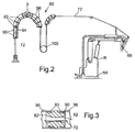
- the string reinforcing material 72 is first threaded through a series of eyelets 82 which are positioned in the manner shown in Figure 2 to provide a 180° curve of the material.
- Each of the eyelets includes a structure 90, as shown in Figure 3, having an internal passageway 92 which allows the string material 72 to be guided therethrough with minimal contact and friction.
- the eyelets 90 are connected to a curved support member 94.
- a series of tubular members 96 are used to enclose the string materials between the individual eyelets 82.
- a balance or tensioning weight 100 supplies the appropriate tension of the string material between the duff or bobbin 70 and the chopper gun 60.
- a second series of eyelets 102 are provided in order to guide the string material 72 from the balance or tensioning weight 100 to the arm 62 of the robot R.
- the eyelets 102 are the same as the eyelets 82 described above.
- Appropriate seals 83 such as 0-rings, are used to hold the tubular members 96 in place on the eyelets 82, 102.
- the tubular members 96 positioned between the eyelets are preferably made from a flexible material, such as polyvinyl chloride (PVC).
- PVC polyvinyl chloride
- the tube members retain the roving within the eyelets.
- the eyelets can be fabricated from a variety of materials, including ceramic, micarta, stainless steel, steel, aluminum, or the like.
- the eyelets are used as a contact surface during the change of direction of the glass material in order to control the material and decrease the contact surface area and friction.
- the tube members are of sufficient diameter so that they will not contact the string reinforcing material as it is passing from the bobbin or doff to the robot.
- the tube members also allow the use of air pressure to help feed the string materials through the eyelets. This eliminates the need to manually feed the material through each individual eyelet.
- the present invention can be used with preformed materials such as glass, carbon, glass/carbon hybrids, and the like.
- the eyelets significantly reduce friction while allowing the string binder materials to be processed in existing chopper guns without modification of them.
- the roving from the doffs or bobbins 70 is broken up or "chopped" by the chopper gun 60 into small pieces of material in the order of 10-50 mm in length, depending on the precise processing system utilized.
- the preferred applicator or chopper gun is supplied by Applicator System AB and includes two separate chopper members, a surface veil chopper and a reinforcement chopper.
- a pneumatic motor drives the surface veil chopper with the feed and knife rollers connected with a drive belt.
- a single-ended roving is used. This allows the fibers to defibrillate or filamentise, yielding a uniform veil mat layer.
- the addition of the chopped veil mat layer assists in removing the part from the mould and can be advantageous to enhance surface quality of the moulded part if required.
- the applicator chopper device has a large processing window and high output capability that significantly reduces preferred fabrication times when compared with traditional chopper guns.
- the chopper gun also preferably processes glass rovings of 2200 to 3500 TEX, rovings of 2400 TEX are preferably used in the preform process.
- the chopper gun utilizes electric servo motors to control the speed of both the feed and knife rollers, thus allowing continuously variable fiber output and fiber length during the preforming process. Fiber output and length control can be changed during the process to eliminate fiber-bridging issues and radii and to obtain net-shape edge characteristics.
- variable air pressure system 110 is utilized, as shown in Figure 7.
- a conventional pneumatic proportional valve 112 is connected to the two air ejectors 114 and 116 in the chopper gun.
- the pneumatic proportional or solenoid valve 112 is controlled by a system computer 120 or the robot R.
- a rigid three-dimensional preform having various thicknesses of material at various portions of the preform component can be manufactured in accordance with the present invention.
- a representative preform product 150 in this regard is shown in Figure 6.
- a "tailor-blanking" process can be utilized which allows the formation of components having the desired thickness for structural rigidity where desired, but allowing the use of thinner portions of the component where the rigidity is not necessary or required.
- any conventional roving can be utilized with the present invention, such as fiberglass roving produced by Owens-Corning.
- the glass roving 15 preferably has a sizing on it which improves the bonding and handling characteristics.
- deposition screen members shaped in the form of the preform are provided in the lower mould portions 24 and 34 of the moulds 20 and 30 respectively.
- the reinforcing roving materials such as string binders, are chopped by the chopper gun 60 and applied along with a thermal plastic or thermoset powder binder to the preformed screens using a robotic routine.
- Positive air flow through the preform deposition screen members holds the chopped materials on the screen surface during the entire spray-up routine. If desired, as mentioned above, a surface veil can be applied first on the screen.
- a surface veil enhances the surface quality of the moulded part and also can be used to prevent flow of the binder through the deposition screen and into the air circulation system.
- the robot R is positioned adjacent the appropriate cell, for example C1, and used to spray the chopped glass and binder to the desired thickness on the preformed screen.
- the moveable frame member 26 with the upper mould portions 22 is automatically moved in position over the lower mould portion 24 and the tool is closed.
- the upper mould portion has a similar consolidation screen member which is shaped to form the finished preform. Ambient temperature air flow through the preform screen is terminated and heated air is drawn through the screens in order to melt the binder 15 on the chopped materials and hold them together. At the same time, the mould is closed compressing the chopped material into the desired size and configuration.
- the heated air flow is stopped and cooled or ambient air is drawn through the preform thereby cooling or freezing the binder and setting the final shape of the preforms.
- the finished preform is removed from the mould and then used as a reinforcement member in the formation of a composite component or product.
- the robot R can be moved along track 66 to its station at cell C2 in order to spray form a second preform.
- the present invention is a fully automated preforming process requiring little or no operator intervention.
- the full process automation is accomplished by the robotics and by automating machine control.
- the process automation provides repeatability in part-to-part consistency as required in high volume automotive applications of composites.
- thermoset binder materials can be used in order to manufacture the preform.
- the use of each of these materials is known in the art and each has its own advantages and disadvantages.
- thermoset binding materials appear to prevent binder migration in the moulded parts, but require higher temperatures and longer holding time to obtain complete cares and to eliminate binder "tackiness" in the preform.
- preforms are used to make composite products, particularly by resin transfer moulding (RTM) or structural reaction injection moulding (SRIM) processes.
- RTM resin transfer moulding
- SRIM structural reaction injection moulding
- the application process of the robot R needs to be programmed.
- the movement of the chopper gun relative to the preform screen needs to be controlled in order to provide the requisite amount of chopped material and binder at the requisite position on the screen.
- the robotic program is automatically generated offline by a robotic software program, such as ROBCAD.
- the present invention allows generation of a robotic program for material deposition with minimal operator intervention. This reduces robotic programming lead time and automates the robotic programming process.
- the software produces the required spray-up routine for the moveable arm 62 and chopper gun 60 on the robot R.
- the fiberglass material can be chopped or broken up into fine pieces, such as 9-10 mm in length.
- the fiberglass can be broken or chopped into pieces, approximately 25-50 mm in length.
- the material used for moulding the structural composite components is typically a polyester or polyurethane material or an epoxy. In the mould the material is injected through the preform and completely around it forming the final product.
- fiberglass and carbon string materials can be broken or chopped up simultaneously or concurrently forming the spray-on material. Doffs or bobbins of each of these materials can be used, together with one or two chopping wheels or knives in the chopper gun or applicator 60.
- the upper mould sections or portions 22 and 32 of moulds 20 and 30, respectively are closed onto the lower moulding tools or portions 24 and 34, respectively. Due to the consistent air flow through the deposition screens in the moulds, higher velocity air flows are created when the two mould portions are being closed for consolidation of the preform. High velocity air flow adjacent the edges of the part can cause the deposit material to move from its original location, however, creating gaps in the sprayed materials or uneven edges.
- seals 120 and 130 are provided, as shown in Figures 4 and 5.
- Seals 120 is provided between the net-edge block 140 and the lower mould portion 24, 34.
- the second seal 130 is provided between the net-edge block 140 and the upper mould portion 22, 32.
- the net-edge blocks 140 are provided around the outer perimeter of the preform 150 in order to contain the sprayed materials and provide a net edge which does not have to be cut or framed afterwards.
- the blocks 140 are provided in the requisite shape to form the perimeter of the preform and are secured to the moulds with screws, bolts, or other fastener members.
- the seals 120 and 130 which preferably are made from an elastomeric material, prevent high velocity air from entering into the internal portion of the mould (mould cavity) when the two mould portions are being closed. Seal 120 prevents high velocity air flow from entering the mould cavity and disturbing the preform between the net-edge block 140 and the lower mould portion, while the seal 130 is provided to prevent high velocity air flow from entering into the mould cavity between the net-edge block and the upper mould portion.
Applications Claiming Priority (4)
| Application Number | Priority Date | Filing Date | Title |
|---|---|---|---|
| US758651 | 1991-09-12 | ||
| US25871900P | 2000-12-29 | 2000-12-29 | |
| US258719P | 2000-12-29 | ||
| US09/758,651 US6527533B2 (en) | 2000-12-29 | 2001-01-11 | Processing systems for automated manufacture of preforms |
Publications (2)
| Publication Number | Publication Date |
|---|---|
| EP1250991A1 true EP1250991A1 (de) | 2002-10-23 |
| EP1250991B1 EP1250991B1 (de) | 2005-09-21 |
Family
ID=26946829
Family Applications (1)
| Application Number | Title | Priority Date | Filing Date |
|---|---|---|---|
| EP01000759A Expired - Lifetime EP1250991B1 (de) | 2000-12-29 | 2001-12-14 | Vorrichtung zur automatisierten Herstellung von Vorformen |
Country Status (4)
| Country | Link |
|---|---|
| US (2) | US6527533B2 (de) |
| EP (1) | EP1250991B1 (de) |
| JP (1) | JP2002225060A (de) |
| DE (1) | DE60113505T2 (de) |
Cited By (8)
| Publication number | Priority date | Publication date | Assignee | Title |
|---|---|---|---|---|
| DE10324735B3 (de) * | 2003-05-30 | 2004-11-11 | Fiber Engineering Gmbh | Verfahren und Vorrichtung zur Herstellung von dreidimensional ausgeprägten Formteilen sowie Formteil |
| CN102365161A (zh) * | 2009-03-06 | 2012-02-29 | Lm玻璃纤维制品有限公司 | 用于制造风力涡轮机叶片的方法及生产线 |
| WO2015170017A1 (fr) | 2014-05-09 | 2015-11-12 | Coriolis Composites | Procede de realisation de preformes par application et formage de fibres orientees |
| WO2015170016A1 (fr) | 2014-05-09 | 2015-11-12 | Coriolis Composites | Procédé et machine pour la réalisation de préformes par application sans compactage de fibres orientées |
| GB2548397A (en) * | 2016-03-18 | 2017-09-20 | Composite Tech And Applications Ltd | Lay-up head |
| FR3098749A1 (fr) | 2019-07-19 | 2021-01-22 | Institut De Recherche Technologique Materiaux, Mettalurgie, Procedes | Procédé de fabrication de préformes pour matériaux composites |
| CN113199779A (zh) * | 2021-05-11 | 2021-08-03 | 中材科技(锡林郭勒)风电叶片有限公司 | 风电叶片模具装配系统 |
| FR3109551A1 (fr) | 2020-04-28 | 2021-10-29 | Institut De Recherche Technologique Jules Verne | Procédé de fabrication d’une préforme tridimensionnelle |
Families Citing this family (28)
| Publication number | Priority date | Publication date | Assignee | Title |
|---|---|---|---|---|
| US6579616B1 (en) * | 1999-03-30 | 2003-06-17 | Owens Corning Fiberglas Technology, Inc. | String binders |
| DE10037773C1 (de) * | 2000-08-03 | 2002-08-22 | Hennecke Gmbh | Verfahren und Vorrichtung zum Herstellen von mit Langfasern verstärkten Kunststoff-Formteilen |
| US6691789B2 (en) | 2001-09-10 | 2004-02-17 | Weatherford/Lamb, Inc. | Expandable hanger and packer |
| US20030215633A1 (en) * | 2002-03-13 | 2003-11-20 | Morris Steven J. | Fiber glass product incorporating string binders |
| FR2882681B1 (fr) * | 2005-03-03 | 2009-11-20 | Coriolis Composites | Tete d'application de fibres et machine correspondante |
| FR2912680B1 (fr) * | 2007-02-21 | 2009-04-24 | Coriolis Composites Sa | Procede et dispositif de fabrication de pieces en materiau composite, en particulier de troncons de fuselage d'avion |
| FR2912953B1 (fr) * | 2007-02-28 | 2009-04-17 | Coriolis Composites Sa | Machine d'application de fibres avec tubes flexibles d'acheminement de fibres |
| FR2913365B1 (fr) * | 2007-03-06 | 2013-07-26 | Coriolis Composites Attn Olivier Bouroullec | Tete d'application de fibres avec systemes de coupe de fibres particuliers |
| FR2913366B1 (fr) * | 2007-03-06 | 2009-05-01 | Coriolis Composites Sa | Tete d'application de fibres avec systemes de coupe et de blocage de fibres particuliers |
| DE602008006013D1 (de) * | 2008-02-22 | 2011-05-19 | Lm Glasfiber As | Verfahren, Vorrichtung und System zur Entdeckung eines Lecks in einem VARTM-Prozess |
| US8701569B2 (en) | 2008-06-20 | 2014-04-22 | Oria Collapsibles, Llc | Pallet design with structural reinforcement |
| US8438981B2 (en) | 2008-06-20 | 2013-05-14 | Oria Collapsibles, Llc | Pallet design with buoyant characteristics |
| US8522694B2 (en) | 2008-06-20 | 2013-09-03 | Oria Collapsibles, Llc | Structural supporting pallet construction with improved perimeter impact absorbing capabilities |
| US8167605B2 (en) * | 2008-06-20 | 2012-05-01 | Oria Collapsibles, Llc | Production assembly and process for mass manufacture of a thermoplastic pallet incorporating a stiffened insert |
| GB2465159B (en) | 2008-11-05 | 2013-04-17 | Aston Martin Lagonda Ltd | Manufacture of a structural composites component |
| FR2943943A1 (fr) * | 2009-04-02 | 2010-10-08 | Coriolis Composites | Procede et machine pour l'application d'une bande de fibres sur des surfaces convexes et/ou avec aretes |
| FR2948059B1 (fr) * | 2009-07-17 | 2011-08-05 | Coriolis Composites | Machine d'application de fibres avec rouleau de compactage transparent au rayonnement du systeme de chauffage |
| FR2948058B1 (fr) * | 2009-07-17 | 2011-07-22 | Coriolis Composites | Machine d'application de fibres comprenant un rouleau de compactage souple avec systeme de regulation thermique |
| US8529818B2 (en) | 2009-09-30 | 2013-09-10 | General Electric Company | Automated fiber placement in female mold |
| WO2011100093A1 (en) * | 2010-01-20 | 2011-08-18 | Graco Minnesota Inc. | Collapsible boom for chopper and wetout fiber reinforced plastic applications |
| US8616110B2 (en) | 2010-09-01 | 2013-12-31 | Ford Global Technologies, Llc | Method and apparatus for making a fiber reinforced article |
| FR2972672B1 (fr) | 2011-03-18 | 2013-03-15 | Coriolis Composites Attn Olivier Bouroullec | Machine d'application de fibres avec systeme de securite |
| FR2975335B1 (fr) * | 2011-05-20 | 2013-05-17 | Coriolis Composites Attn Olivier Bouroullec | Machine d'application de fibres avec tubes flexibles d'acheminement de fibres munis de lames flexibles |
| DE102014110909A1 (de) | 2014-07-31 | 2016-02-04 | Deutsches Zentrum für Luft- und Raumfahrt e.V. | Faserlegevorrichtung |
| FR3034338B1 (fr) | 2015-04-01 | 2017-04-21 | Coriolis Composites | Tete d'application de fibres avec rouleau d'application particulier |
| FR3043010B1 (fr) | 2015-10-28 | 2017-10-27 | Coriolis Composites | Machine d'application de fibres avec systemes de coupe particuliers |
| FR3048373B1 (fr) | 2016-03-07 | 2018-05-18 | Coriolis Group | Procede de realisation de preformes avec application d'un liant sur fibre seche et machine correspondante |
| FR3056438B1 (fr) | 2016-09-27 | 2019-11-01 | Coriolis Group | Procede de realisation de pieces en materiau composite par impregnation d'une preforme particuliere. |
Citations (3)
| Publication number | Priority date | Publication date | Assignee | Title |
|---|---|---|---|---|
| US4117067A (en) * | 1975-12-31 | 1978-09-26 | Owens-Corning Fiberglas Corporation | High production method of producing glass fiber resin composites and articles produced thereby |
| FR2639867A1 (fr) * | 1988-12-06 | 1990-06-08 | Behar Isaac | Procede d'estampage d'un materiau composite thermoplastique |
| US5338169A (en) * | 1990-11-05 | 1994-08-16 | The C. A. Lawton Company | Apparatus for making preforms |
Family Cites Families (4)
| Publication number | Priority date | Publication date | Assignee | Title |
|---|---|---|---|---|
| US4167378A (en) * | 1976-02-06 | 1979-09-11 | Mo Och Domsjo Ab | Apparatus for shredding and dry-defibrating compressed cellulose pulp and forming a batt of the resulting cellulosic fibrous material |
| US4872825A (en) * | 1984-05-23 | 1989-10-10 | Ross Milton I | Method and apparatus for making encapsulated electronic circuit devices |
| DE3507720C2 (de) * | 1985-03-05 | 1997-08-14 | Rieter Automotive Int Ag | Verfahren und Vorrichtung zum Herstellen eines Rohlings aus glasfaserverstärktem Kunststoff |
| US5178885A (en) * | 1989-06-20 | 1993-01-12 | United Technologies Corporation | Resin transfer mold |
-
2001
- 2001-01-11 US US09/758,651 patent/US6527533B2/en not_active Expired - Lifetime
- 2001-12-14 EP EP01000759A patent/EP1250991B1/de not_active Expired - Lifetime
- 2001-12-14 DE DE60113505T patent/DE60113505T2/de not_active Expired - Lifetime
- 2001-12-27 JP JP2001396815A patent/JP2002225060A/ja active Pending
-
2003
- 2003-02-07 US US10/360,895 patent/US6890465B2/en not_active Expired - Lifetime
Patent Citations (3)
| Publication number | Priority date | Publication date | Assignee | Title |
|---|---|---|---|---|
| US4117067A (en) * | 1975-12-31 | 1978-09-26 | Owens-Corning Fiberglas Corporation | High production method of producing glass fiber resin composites and articles produced thereby |
| FR2639867A1 (fr) * | 1988-12-06 | 1990-06-08 | Behar Isaac | Procede d'estampage d'un materiau composite thermoplastique |
| US5338169A (en) * | 1990-11-05 | 1994-08-16 | The C. A. Lawton Company | Apparatus for making preforms |
Cited By (13)
| Publication number | Priority date | Publication date | Assignee | Title |
|---|---|---|---|---|
| DE10324735B3 (de) * | 2003-05-30 | 2004-11-11 | Fiber Engineering Gmbh | Verfahren und Vorrichtung zur Herstellung von dreidimensional ausgeprägten Formteilen sowie Formteil |
| CN102365161A (zh) * | 2009-03-06 | 2012-02-29 | Lm玻璃纤维制品有限公司 | 用于制造风力涡轮机叶片的方法及生产线 |
| EP2403707B2 (de) † | 2009-03-06 | 2022-03-16 | LM Glasfiber A/S | Verfahren und fertigungsstrasse zur herstellung von windturbinenschaufeln |
| WO2015170017A1 (fr) | 2014-05-09 | 2015-11-12 | Coriolis Composites | Procede de realisation de preformes par application et formage de fibres orientees |
| WO2015170016A1 (fr) | 2014-05-09 | 2015-11-12 | Coriolis Composites | Procédé et machine pour la réalisation de préformes par application sans compactage de fibres orientées |
| GB2548397B (en) * | 2016-03-18 | 2021-07-21 | Rolls Royce Plc | Lay-up head |
| GB2548397A (en) * | 2016-03-18 | 2017-09-20 | Composite Tech And Applications Ltd | Lay-up head |
| US10173378B2 (en) | 2016-03-18 | 2019-01-08 | Composite Technology & Applications Limited | Lay-up head |
| FR3098749A1 (fr) | 2019-07-19 | 2021-01-22 | Institut De Recherche Technologique Materiaux, Mettalurgie, Procedes | Procédé de fabrication de préformes pour matériaux composites |
| WO2021013769A1 (fr) | 2019-07-19 | 2021-01-28 | Institut De Recherche Technologique Matériaux, Métallurgie, Procédés | Procédé de fabrication de préformes pour matériaux composites |
| FR3109551A1 (fr) | 2020-04-28 | 2021-10-29 | Institut De Recherche Technologique Jules Verne | Procédé de fabrication d’une préforme tridimensionnelle |
| WO2021219593A1 (fr) | 2020-04-28 | 2021-11-04 | Institut De Recherche Technologique Jules Verne | Procede de fabrication d'une preforme tridimensionnelle |
| CN113199779A (zh) * | 2021-05-11 | 2021-08-03 | 中材科技(锡林郭勒)风电叶片有限公司 | 风电叶片模具装配系统 |
Also Published As
| Publication number | Publication date |
|---|---|
| US20020090408A1 (en) | 2002-07-11 |
| JP2002225060A (ja) | 2002-08-14 |
| DE60113505T2 (de) | 2006-07-06 |
| US20030118681A1 (en) | 2003-06-26 |
| US6527533B2 (en) | 2003-03-04 |
| EP1250991B1 (de) | 2005-09-21 |
| US6890465B2 (en) | 2005-05-10 |
| DE60113505D1 (de) | 2006-02-02 |
Similar Documents
| Publication | Publication Date | Title |
|---|---|---|
| EP1250991B1 (de) | Vorrichtung zur automatisierten Herstellung von Vorformen | |
| JP4376968B2 (ja) | ポリマーと複合物の成品の製造のための方法と設備 | |
| US11260606B2 (en) | Automated resin and fiber deposition for resin infusion | |
| US4952366A (en) | Molding process | |
| US5034181A (en) | Apparatus for and method of manufacturing preforms | |
| US6497566B2 (en) | Robotic systems for automated preform processing | |
| JP2011251677A (ja) | 湾曲複合フレーム及び湾曲複合フレームの製造方法 | |
| EP3397457A1 (de) | Maschine und verfahren zur herstellung von artikeln | |
| US6540495B2 (en) | Air flow systems for automated preform processing | |
| Kordi et al. | Development of a multifunctional robot end-effector system for automated manufacture of textile preforms | |
| CN106926478A (zh) | 碳纤维汽车零部件hp‑rtm连续生产线及其生产方法 | |
| US20030196743A1 (en) | Apparatus and methods for producing tow based patterns | |
| WO2021167504A1 (en) | A curved aerospace profile article and method of manufacture of the article | |
| US20210276688A1 (en) | Shaped Composite Vehicle Skins and Method for High Rate Manufacturing of Same | |
| Lengsfeld et al. | Prepregs: Processing Technology | |
| Jarvis | Automated lay-up of composite blades | |
| CN115534351A (zh) | 一种连续纤维增强预浸料模压成型方法 | |
| CN115771262A (zh) | 基于纤维复合材料的3d打印方法及装置 | |
| JPH04125134A (ja) | 繊維強化樹脂成形体の製造方法 | |
| MANUAL et al. | TRIM 6 |
Legal Events
| Date | Code | Title | Description |
|---|---|---|---|
| PUAI | Public reference made under article 153(3) epc to a published international application that has entered the european phase |
Free format text: ORIGINAL CODE: 0009012 |
|
| AK | Designated contracting states |
Kind code of ref document: A1 Designated state(s): AT BE CH CY DE DK ES FI FR GB GR IE IT LI LU MC NL PT SE TR |
|
| AX | Request for extension of the european patent |
Free format text: AL;LT;LV;MK;RO;SI |
|
| 17P | Request for examination filed |
Effective date: 20030326 |
|
| AKX | Designation fees paid |
Designated state(s): DE FR GB IT SE |
|
| 17Q | First examination report despatched |
Effective date: 20030829 |
|
| GRAP | Despatch of communication of intention to grant a patent |
Free format text: ORIGINAL CODE: EPIDOSNIGR1 |
|
| GRAS | Grant fee paid |
Free format text: ORIGINAL CODE: EPIDOSNIGR3 |
|
| GRAA | (expected) grant |
Free format text: ORIGINAL CODE: 0009210 |
|
| AK | Designated contracting states |
Kind code of ref document: B1 Designated state(s): DE FR GB IT SE |
|
| PG25 | Lapsed in a contracting state [announced via postgrant information from national office to epo] |
Ref country code: IT Free format text: LAPSE BECAUSE OF FAILURE TO SUBMIT A TRANSLATION OF THE DESCRIPTION OR TO PAY THE FEE WITHIN THE PRESCRIBED TIME-LIMIT;WARNING: LAPSES OF ITALIAN PATENTS WITH EFFECTIVE DATE BEFORE 2007 MAY HAVE OCCURRED AT ANY TIME BEFORE 2007. THE CORRECT EFFECTIVE DATE MAY BE DIFFERENT FROM THE ONE RECORDED. Effective date: 20050921 |
|
| REG | Reference to a national code |
Ref country code: GB Ref legal event code: FG4D |
|
| REF | Corresponds to: |
Ref document number: 60113505 Country of ref document: DE Date of ref document: 20051027 Kind code of ref document: P |
|
| REG | Reference to a national code |
Ref country code: GB Ref legal event code: 732E |
|
| PGFP | Annual fee paid to national office [announced via postgrant information from national office to epo] |
Ref country code: FR Payment date: 20051201 Year of fee payment: 5 |
|
| PG25 | Lapsed in a contracting state [announced via postgrant information from national office to epo] |
Ref country code: SE Free format text: LAPSE BECAUSE OF FAILURE TO SUBMIT A TRANSLATION OF THE DESCRIPTION OR TO PAY THE FEE WITHIN THE PRESCRIBED TIME-LIMIT Effective date: 20051221 |
|
| REF | Corresponds to: |
Ref document number: 60113505 Country of ref document: DE Date of ref document: 20060202 Kind code of ref document: P |
|
| PLBE | No opposition filed within time limit |
Free format text: ORIGINAL CODE: 0009261 |
|
| STAA | Information on the status of an ep patent application or granted ep patent |
Free format text: STATUS: NO OPPOSITION FILED WITHIN TIME LIMIT |
|
| 26N | No opposition filed |
Effective date: 20060622 |
|
| PG25 | Lapsed in a contracting state [announced via postgrant information from national office to epo] |
Ref country code: FR Free format text: LAPSE BECAUSE OF FAILURE TO SUBMIT A TRANSLATION OF THE DESCRIPTION OR TO PAY THE FEE WITHIN THE PRESCRIBED TIME-LIMIT Effective date: 20061020 |
|
| EN | Fr: translation not filed | ||
| REG | Reference to a national code |
Ref country code: GB Ref legal event code: 746 Effective date: 20061116 |
|
| REG | Reference to a national code |
Ref country code: DE Ref legal event code: R082 Ref document number: 60113505 Country of ref document: DE Representative=s name: WITTE, WELLER & PARTNER, DE |
|
| REG | Reference to a national code |
Ref country code: GB Ref legal event code: 732E Free format text: REGISTERED BETWEEN 20130829 AND 20130904 |
|
| REG | Reference to a national code |
Ref country code: DE Ref legal event code: R082 Ref document number: 60113505 Country of ref document: DE Representative=s name: WITTE, WELLER & PARTNER, DE Effective date: 20130924 Ref country code: DE Ref legal event code: R081 Ref document number: 60113505 Country of ref document: DE Owner name: ASTON MARTIN LAGONDA LIMITED, GB Free format text: FORMER OWNER: FORD GLOBAL TECHNOLOGIES, LLC (N.D.GES.D. STAATES DELAWARE), DEARBORN, US Effective date: 20130924 Ref country code: DE Ref legal event code: R081 Ref document number: 60113505 Country of ref document: DE Owner name: ASTON MARTIN LAGONDA LIMITED, GAYDON, GB Free format text: FORMER OWNER: FORD GLOBAL TECHNOLOGIES, LLC (N.D.GES.D. STAATES DELAWARE), DEARBORN, MICH., US Effective date: 20130924 Ref country code: DE Ref legal event code: R082 Ref document number: 60113505 Country of ref document: DE Representative=s name: WITTE, WELLER & PARTNER PATENTANWAELTE MBB, DE Effective date: 20130924 |
|
| PGFP | Annual fee paid to national office [announced via postgrant information from national office to epo] |
Ref country code: GB Payment date: 20201215 Year of fee payment: 20 |
|
| PGFP | Annual fee paid to national office [announced via postgrant information from national office to epo] |
Ref country code: DE Payment date: 20201217 Year of fee payment: 20 |
|
| REG | Reference to a national code |
Ref country code: DE Ref legal event code: R071 Ref document number: 60113505 Country of ref document: DE |
|
| REG | Reference to a national code |
Ref country code: GB Ref legal event code: PE20 Expiry date: 20211213 |
|
| PG25 | Lapsed in a contracting state [announced via postgrant information from national office to epo] |
Ref country code: GB Free format text: LAPSE BECAUSE OF EXPIRATION OF PROTECTION Effective date: 20211213 |