EP1250860B1 - Sole - Google Patents
Sole Download PDFInfo
- Publication number
- EP1250860B1 EP1250860B1 EP02008200A EP02008200A EP1250860B1 EP 1250860 B1 EP1250860 B1 EP 1250860B1 EP 02008200 A EP02008200 A EP 02008200A EP 02008200 A EP02008200 A EP 02008200A EP 1250860 B1 EP1250860 B1 EP 1250860B1
- Authority
- EP
- European Patent Office
- Prior art keywords
- sole
- receptacle
- stud
- insert
- fastening projection
- Prior art date
- Legal status (The legal status is an assumption and is not a legal conclusion. Google has not performed a legal analysis and makes no representation as to the accuracy of the status listed.)
- Expired - Lifetime
Links
- 229910052751 metal Inorganic materials 0.000 claims description 15
- 239000002184 metal Substances 0.000 claims description 15
- 239000000463 material Substances 0.000 claims description 14
- 238000001746 injection moulding Methods 0.000 claims description 8
- 238000002347 injection Methods 0.000 claims description 7
- 239000007924 injection Substances 0.000 claims description 7
- 230000002787 reinforcement Effects 0.000 claims description 4
- 238000004519 manufacturing process Methods 0.000 description 11
- 238000003780 insertion Methods 0.000 description 7
- 230000037431 insertion Effects 0.000 description 7
- 239000004033 plastic Substances 0.000 description 5
- 239000004952 Polyamide Substances 0.000 description 3
- 229920002647 polyamide Polymers 0.000 description 3
- 229910000831 Steel Inorganic materials 0.000 description 2
- 230000006978 adaptation Effects 0.000 description 2
- 238000010276 construction Methods 0.000 description 2
- 239000003292 glue Substances 0.000 description 2
- 230000003993 interaction Effects 0.000 description 2
- JEIPFZHSYJVQDO-UHFFFAOYSA-N iron(III) oxide Inorganic materials O=[Fe]O[Fe]=O JEIPFZHSYJVQDO-UHFFFAOYSA-N 0.000 description 2
- 230000004048 modification Effects 0.000 description 2
- 238000012986 modification Methods 0.000 description 2
- 230000003014 reinforcing effect Effects 0.000 description 2
- 239000010959 steel Substances 0.000 description 2
- 229910052782 aluminium Inorganic materials 0.000 description 1
- XAGFODPZIPBFFR-UHFFFAOYSA-N aluminium Chemical compound [Al] XAGFODPZIPBFFR-UHFFFAOYSA-N 0.000 description 1
- 238000004873 anchoring Methods 0.000 description 1
- 230000001419 dependent effect Effects 0.000 description 1
- 239000013013 elastic material Substances 0.000 description 1
- 239000011888 foil Substances 0.000 description 1
- 239000003365 glass fiber Substances 0.000 description 1
- 230000007246 mechanism Effects 0.000 description 1
- 150000002739 metals Chemical class 0.000 description 1
- 238000000465 moulding Methods 0.000 description 1
- 230000000149 penetrating effect Effects 0.000 description 1
Images


Classifications
-
- A—HUMAN NECESSITIES
- A43—FOOTWEAR
- A43C—FASTENINGS OR ATTACHMENTS OF FOOTWEAR; LACES IN GENERAL
- A43C15/00—Non-skid devices or attachments
- A43C15/16—Studs or cleats for football or like boots
- A43C15/168—Studs or cleats for football or like boots with resilient means, e.g. shock absorbing means
-
- A—HUMAN NECESSITIES
- A43—FOOTWEAR
- A43B—CHARACTERISTIC FEATURES OF FOOTWEAR; PARTS OF FOOTWEAR
- A43B13/00—Soles; Sole-and-heel integral units
- A43B13/14—Soles; Sole-and-heel integral units characterised by the constructive form
- A43B13/22—Soles made slip-preventing or wear-resisting, e.g. by impregnation or spreading a wear-resisting layer
- A43B13/24—Soles made slip-preventing or wear-resisting, e.g. by impregnation or spreading a wear-resisting layer by use of insertions
- A43B13/26—Soles made slip-preventing or wear-resisting, e.g. by impregnation or spreading a wear-resisting layer by use of insertions projecting beyond the sole surface
-
- A—HUMAN NECESSITIES
- A43—FOOTWEAR
- A43C—FASTENINGS OR ATTACHMENTS OF FOOTWEAR; LACES IN GENERAL
- A43C15/00—Non-skid devices or attachments
- A43C15/16—Studs or cleats for football or like boots
- A43C15/161—Studs or cleats for football or like boots characterised by the attachment to the sole
Definitions
- the present invention relates to a sole with at least one receptacle and at least one stud which can be releasably mounted in the receptacle by inserting.
- the stud is for an adaptation releasably attached to the sole.
- studs for soccer shoes have been known for many years, which are connected to the sole by means of threads.
- the releasable attachment further allows the replacement of worn studs, so that a new shoe is not necessary.
- a metal socket with a circular snap ring is provided in the receptacle of the US 5,638,615.
- the snap ring is made from flexible steel and together with the socket arranged in the receptacle for the stud during the manufacture of the sole.
- the snap ring is expanded before it snaps into an annular groove of the base portion and thereby fastens the stud.
- the rotationally symmetric form of the receptacle and the stud allows a rotation of the mounted stud in the receptacle.
- the US 5,848,482 relates to a cleat assembly for shoes which comprises a cleat body and a cooperating receptacle.
- the receptacle is incorporated into a shoe outsole and has an elongated cavity with a central post.
- the cleat body is pressed into the receptacle wherein the attachment stud enters the cavity and the axial longitudinal bore of the attachment stud receives a post within the cavity.
- the EP 0 998 862 A1 relates to a studded shoe with a stud-fastening mechanism which is preferably used for elongate studs.
- the present invention is defined in independent claim 1.
- the arrangement of the elastic wall of the receptacle provides according to the invention a "spring element" which allows the locking of the two locking means, when the fastening projection of the stud is inserted.
- An additional metal spring or the like is not necessary. Thus, the costs for the manufacture of the sole are considerably reduced.
- a cavity is provided in the sole adjacent to the receptacle, so that the elastic wall is during the insertion of the fastening projection deflected into the cavity. This facilitates the elastic properties of the wall without having to provide special elastic materials in the receptacle.
- the cavity and the flexible wall are preferably integrally formed together with the other parts of the sole, for example by injection molding as a single piece.
- the first locking means is formed as a recess in the fastening projection and the second locking means is formed as a corresponding projection of the elastic wall engaging during locking the recess.
- the first locking means is formed as a projection and the second locking means as a corresponding recess of the elastic wall, which is engaged during locking by the projection. In both embodiments, the elastic wall is pressed into the cavity during the insertion of the fastening portion until the projection and the corresponding recess are in the same position and engage each other.
- the cavity is preferably provided as a recess open to the top side of the sole. This design facilitates the removal from the mold, if the sole is manufactured by injection molding of a plastic material.
- the fastening projection of the stud is oblong and the wall between the cavity and the receptacle is essentially parallel to the longitudinal axis of the fastening projection.
- the stud is secured against rotation in the receptacle without high constructional effort.
- the fastening projection and the receptacle have corresponding asymmetric shapes defining unambiguously an orientation of the mounted stud. This ensures a correct arrangement of the stud, even if the attachment is performed in a great hurry, for example during a game.
- a first and a second cavity are arranged on opposite sides of the receptacle and the elastic walls between the cavities and the receptacle extend essentially parallel to the longitudinal axis of the fastening projection.
- two first locking means are arranged on the two longitudinal sides of the fastening projection and two second locking means are arranged on the corresponding elastic walls.
- the stud comprises an engaging means below the fastening projection, which is preferably formed as two recesses arranged on opposite sides of the stud.
- the necessary vertical force can be applied to pull the stud out of the receptacle.
- the lower part of the receptacle is reinforced by an additional insert, wherein the sole is preferably made of a material injection molded around the insert.
- the materials of the insert and the sole are preferably compatible to achieve a good bonding during the injection molding of the sole around the insert.
- the insert collar-like encompasses the fastening projection of the mounted stud and comprises cutouts corresponding to the first and second locking means of the stud and the elastic wall. This allows in spite of the reinforcement of the seat of the stud by the insert an unhindered interaction of the first and second locking means.
- the insert comprises a metal reinforcement, which is preferably provided as a ring, that also encompasses the fastening projection of the mounted stud. It is advantageous, if the insert is made from a material, which is injection molded around the metal ring.
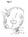
- Fig. 1 presents a view of the front part of a preferred embodiment of the sole 1 according to the invention with a plurality of base members 10 for releasably attached studs 20.
- the arrangement of the base members 10 along the edge of the sole is exemplary for many possible configurations, as they are used in soccer shoes. Additionally, base members 10 are in this case also arranged in the heel part (not shown).
- one or more studs 2 can be provided which are undetachably anchored to the sole.
- the stud 20 is releasably mounted to the sole 1 by a simple insertion of its fastening projection 21 into a receptacle 11 of the corresponding base member 10. Neither screwing, nor any additional rotation, nor any other actions are necessary for the attachment after the insertion.
- slit-like recesses 22 are preferably provided on the sides of the stud 20, which can be engaged by a suitable claw-like tool (not shown) to securely catch the stud 20.
- a suitable claw-like tool not shown
- other devices can be provided for the engagement with the tool, for example circular recesses or all kinds of suitable lateral protrusions.
- the described way of mounting allows an extremely fast replacement of all studs 20 of the shoe sole 1, so that the gripping properties of the shoe can be quickly adapted to changing ground conditions, even during a game.
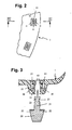
- Fig. 2 shows a detailed view of the sole 1 of Fig. 1 from above.
- two inwardly directed projections 12 are arranged inside the receptacle 11 of the base member 10, which engage corresponding recesses 23 of the fastening projection 21 of the stud 20, when it is completely inserted into the receptacle 11.
- the inverted arrangement is also possible, i.e. the provision of lateral projections on the fastening projection 21 of the stud engaging corresponding recesses of the receptacle 11.
- Fig. 3 shows an enlarged presentation of the base member 10.
- two cavities 15 are arranged directly adjacent to the longitudinal sides of the receptacle 11.
- the top view in Fig. 2 and the cross section in Fig. 3 show that the cavities 15 are essentially shaped as oblong recesses in the base member 10, which are open to the top side.
- the complete sole is made by injection molding as a single piece of plastic including all base members 10 and receptacles 11.
- the cavity 15 can, if necessary, also be manufactured with a closed top side.
- Such a closed top side could for example be provided by an additional foil (not shown) closing the cavities 15 after molding the sole, in order to avoid that glue for attaching a further insole enters the cavities 15.
- the fastening projection 21 When, as indicated in Fig. 3 by the vertical arrow, the fastening projection 21 is inserted into the receptacle 11, its upper end pushes the projections 12 apart (cf. the black arrows in Fig. 3). This is possible, since the wall 16 positioned between the receptacle 11 and the respective cavity 15 has a certain elasticity and can therefore be deflected like a spring into the cavity 15.
- the material used for the sole determines together with the thickness and the length of the elastic wall 16 the resistance when the fastening projection 21 is inserted, until the locking takes place.
- the projections 12 or the upper end of the fastening projection 21 can be advantageous to provide with laterally inclined edges (not shown) to facilitate the insertion.
- the projections 12 are preferably arranged in the upper part of the walls 16 so that the major lower part of the receptacle 11 is capable to provide a reliable seat for the fastening projection 21.
- the projections 12 engage the recesses 23 due to the elastic spring-back of the walls 16 between the cavities 15 and the receptacle 11 and thereby fasten the stud 20 to the sole 1.
- the sole 1 itself integrally comprises the two cavities 15 and the intermediate walls 16, i.e. elastic spring elements, which reliably anchor the fastening projection 21 in the receptacle 11.
- the manufacture requires only the injection molding of the sole and the production of corresponding studs.
- Fig. 3 shows as well as Fig. 1 that the base member 10 itself extends like a stud downwardly from the sole 1.
- the base member 10 has on the one hand a certain grip-improving function, on the other hand a space is provided in the sole 1, which is necessary for the arrangement of the receptacle 11 and the cavities 15 according to the invention.
- the enlarged base member 10 prevents an excessive strain on the sole area, so that a breaking-off of single studs is even under peak loads avoided.
- the base member 10 can also be integrated into the sole 1 in a way that the lower opening of the receptacle 11 is planar with the lower side of the sole 1.
- the Figs. 4 to 7 illustrate a further embodiment of the present invention including an additional insert 30 for reinforcing the lower part of the receptacle 11.
- the additional insert 30 is collar-like arranged around the fastening projection 21 of the stud 20 and stabilizes its seat at the sole 1.
- the insert 30 is at first injection molded from a first material. Subsequently, the insert 30 is (together with other, similar inserts) arranged in the mold for the sole 1, which is then injection molded from a second material around the inserts 30.
- the first and the second material are preferably compatible to each other so that a reliable bonding between the sole 1 and the insert 30 is obtained during the injection molding step of the sole 1.
- the sole 1 is made of a polyamide and the insert 30 is made of a glass-fiber reinforced polyamide for greater strength.
- the preferred shape of the insert 30 is shown in the top and side views of Fig. 5a - 5c.
- Contact areas 33 are provided at the front and rear end of the oblong insert 30, which assure a reliable bonding to the surrounding sole body of the base member 10.
- Cutouts 31 are arranged along the longitudinal sides of the insert 30 allowing an unhindered interaction of the locking means 12, 23 of the fastening projection 21 of the stud 20 and the elastic wall 16 of the base member 10.
- the preferred insert 30 does not directly participate in the elastic locking of the stud, but only reinforces the lowermost part of the base member 10.
- a lowermost projection 32 of the insert 30, which fits into a corresponding recess 29 of the top surface of the stud 20 further increases the stability of the seat at the sole 1.
- the insert 30 is further strengthened by embedding a metal ring 40 therein.
- a metal ring 40 This is schematically indicated in the explosionary view of Fig. 4. and by the dashed lines in Fig. 5a showing a top view of the insert 30.
- the ring can be made from any suitable metal, for example steel. Since the ring is at least partly embedded in surrounding plastic material, it is less susceptible to rust.
- ring does not require a circular structure. Instead, any shape that helps to reduce a deformation of the insert 30 (and thereby the base member 10) under load is suitable. Further, although the embedded ring 40, as shown in the Figs. 5a, 5b, 5c, 6 and 7, is planar, a three-dimensional shape is also conceivable.
- the insert 30 is preferably injection molded around the ring 40, so that manual assembly steps are avoided.
- the fastening projection 21 of the stud 20 has as well as the corresponding receptacle 11 an oblong shape and the cavities 15 extend essentially parallel thereto.
- the seat of the stud 20, which has also an oblong shape is secured against rotation.
- the shape of the fastening projection 21 can be slightly conical, defining thereby unambiguously the orientation of the stud 20 at the sole. In the embodiment of Figs. 4 - 7 this is further reflected by a corresponding shape of the of the opening of the insert 30 and the ring 40. If there are different studs 20 provided for different locations at the sole, it is further possible to provide individually designed receptacles 11 and fastening projections 21, so that each stud fits only into its corresponding receptacle 11.
- cavities 15' and corresponding walls 16' which are semi-circularly shaped and which surround the ends of the oblong receptacle 11.
- Such an alternative configuration is schematically shown in the top view of Fig. 8.
- Conceivable is also a modification of the design according to the invention, wherein one or more cavities 15 with corresponding walls 16 having projections or recesses are arranged around a rotationally symmetric receptacle 11, so that a rotation of the fastening projection 21 is possible inside the receptacle 11.
- the receptacle 11 could be surrounded by a plurality, for example three, cavities 15 with corresponding walls 16.
- the studs 20 can as well as the sole 1 be manufactured from suitable plastic materials like polyamides. Alternatively, aluminum or other metals, which combine a low weight with high wear resistance, can be used for the studs 20. In case of metal studs, it is advantageous, if the fastening projection 21 is coated with a plastic layer which can slightly deform during insertion into the receptacle 11.
Landscapes
- Footwear And Its Accessory, Manufacturing Method And Apparatuses (AREA)
- Golf Clubs (AREA)
- Steroid Compounds (AREA)
Applications Claiming Priority (2)
| Application Number | Priority Date | Filing Date | Title |
|---|---|---|---|
| DE10118986A DE10118986B4 (de) | 2001-04-18 | 2001-04-18 | Sohle |
| DE10118986 | 2001-04-18 |
Publications (2)
| Publication Number | Publication Date |
|---|---|
| EP1250860A1 EP1250860A1 (en) | 2002-10-23 |
| EP1250860B1 true EP1250860B1 (en) | 2006-10-11 |
Family
ID=7681840
Family Applications (1)
| Application Number | Title | Priority Date | Filing Date |
|---|---|---|---|
| EP02008200A Expired - Lifetime EP1250860B1 (en) | 2001-04-18 | 2002-04-17 | Sole |
Country Status (5)
| Country | Link |
|---|---|
| US (1) | US6748677B2 (enExample) |
| EP (1) | EP1250860B1 (enExample) |
| JP (1) | JP2002325604A (enExample) |
| AT (1) | ATE341958T1 (enExample) |
| DE (2) | DE10118986B4 (enExample) |
Cited By (1)
| Publication number | Priority date | Publication date | Assignee | Title |
|---|---|---|---|---|
| US12495868B2 (en) | 2015-01-15 | 2025-12-16 | Adidas Ag | Baseplate for a shoe |
Families Citing this family (26)
| Publication number | Priority date | Publication date | Assignee | Title |
|---|---|---|---|---|
| US7752775B2 (en) | 2000-03-10 | 2010-07-13 | Lyden Robert M | Footwear with removable lasting board and cleats |
| USD532960S1 (en) * | 2001-01-26 | 2006-12-05 | Penguin Brands, Inc. | Cleat |
| DE10248482B4 (de) * | 2002-10-17 | 2005-09-22 | Adidas International Marketing B.V. | Sohle und Verfahren zur Herstellung einer Sohle |
| US7047675B2 (en) * | 2001-04-18 | 2006-05-23 | Adidas International Marketing B.V. | Detachable cleat system |
| US6722061B2 (en) | 2001-11-20 | 2004-04-20 | Nike, Inc. | Article of footwear with a replaceable ground-engaging member and method of attaching the ground-engaging member |
| DE10241153B3 (de) * | 2002-09-05 | 2004-04-08 | Adidas International Marketing B.V. | Stollen und Schuh |
| US7579055B2 (en) * | 2003-07-08 | 2009-08-25 | Taylor Made Golf Co., Inc. | Sole construction for an athletic shoe |
| DE102004011680B4 (de) * | 2004-03-10 | 2007-08-23 | Adidas International Marketing B.V. | Stollenschuh |
| DE202005001354U1 (de) * | 2005-01-28 | 2006-06-08 | Puma Aktiengesellschaft Rudolf Dassler Sport | Schuhsohle, insbesondere für einen Sportschuh |
| US20070024825A1 (en) * | 2005-07-26 | 2007-02-01 | Stephanes Maria De Vaan Adrian | Light valve projection systems with light recycling |
| US7866064B2 (en) | 2007-02-16 | 2011-01-11 | Nike, Inc. | Interchangeable pod system |
| US20080229620A1 (en) * | 2007-03-19 | 2008-09-25 | Alcoa Global Fasteners | Double flush fastener for attaching cleats |
| WO2008156825A1 (en) * | 2007-06-20 | 2008-12-24 | Taylor Made Golf Company, Inc. | Article of footwear with traction members having a low profile sole |
| US20110010964A1 (en) * | 2007-11-07 | 2011-01-20 | Linckia Development Llc | Footwear suspension system |
| US8720086B2 (en) * | 2008-03-20 | 2014-05-13 | Nike, Inc. | Cleat member for article of footwear |
| US8291621B2 (en) * | 2008-04-03 | 2012-10-23 | Nike, Inc. | Article of footwear with a cleat member |
| US9220319B2 (en) * | 2012-05-15 | 2015-12-29 | Nike, Inc. | Spike for footwear having rigid portion and resilient portion |
| US9615621B2 (en) | 2012-06-04 | 2017-04-11 | Nike, Inc. | Sole structure with integrated cleat member and methods of making |
| US9883714B2 (en) * | 2013-06-14 | 2018-02-06 | Nike, Inc. | Sole plate assembly and method of making |
| DE102013213582A1 (de) * | 2013-07-11 | 2015-01-29 | Evonik Industries Ag | Sportschuh umfassend stollen oder stollenaufnahmen |
| US10123588B2 (en) | 2013-12-31 | 2018-11-13 | Nike, Inc. | Footwear ground engaging members having concave portions |
| US10028551B2 (en) * | 2014-04-24 | 2018-07-24 | Nike, Inc. | Interchangeable chassis for cleated footwear |
| DE102015200526B4 (de) | 2015-01-15 | 2016-11-24 | Adidas Ag | Bodenplatte für einen Schuh, insbesondere einen Sportschuh |
| US10206453B2 (en) | 2016-02-12 | 2019-02-19 | Wolverine Outdoors, Inc. | Footwear including a support cage |
| US10834998B2 (en) | 2018-04-13 | 2020-11-17 | Wolverine Outdoors, Inc. | Footwear including a holding cage |
| JP2023131965A (ja) * | 2022-03-10 | 2023-09-22 | 美津濃株式会社 | アウトソールのスタッド、クリーツシューズ用のアウトソール、アウトソールの製造方法、およびクリーツシューズ |
Family Cites Families (13)
| Publication number | Priority date | Publication date | Assignee | Title |
|---|---|---|---|---|
| US1141889A (en) * | 1914-12-23 | 1915-06-01 | Racine Aluminum Shoe Company | Boot, shoe, and the like. |
| US2607134A (en) * | 1949-05-27 | 1952-08-19 | Claude Harmon | Calk for footwear |
| US3054197A (en) * | 1958-04-21 | 1962-09-18 | John T Riddell Inc | Snap-on shoe cleat asembly |
| US4035934A (en) * | 1976-08-26 | 1977-07-19 | Hrivnak Andrew N | Assembly spike for athletic shoe |
| BR8503313A (pt) | 1984-07-19 | 1986-04-01 | Dassler Puma Sportschuh | Sapato esportivo com uma sola apresentando elementos pegadores substituiveis |
| DE3505665A1 (de) | 1985-02-19 | 1986-08-21 | Puma-Sportschuhfabriken Rudolf Dassler Kg, 8522 Herzogenaurach | Sportschuh |
| DE9214782U1 (de) * | 1992-10-31 | 1994-03-03 | Puma Ag Rudolf Dassler Sport, 91074 Herzogenaurach | Sportschuh mit einer Laufsohle mit Halterungseinsätzen zur Halterung von Greifelementen |
| US5475937A (en) * | 1994-05-25 | 1995-12-19 | Korsen; David L. | Shoe spike apparatus |
| US6108944A (en) * | 1996-01-17 | 2000-08-29 | Macneill Engineering Company, Inc. | Quick-release connector |
| US5848482A (en) * | 1996-12-18 | 1998-12-15 | Bathum; Dale | Cleat assembly for shoes |
| WO1999045811A1 (en) * | 1998-03-13 | 1999-09-16 | Yasuhiro Ijiri | Slipping prevention device for footwear |
| DE29807082U1 (de) * | 1998-04-21 | 1998-06-10 | Produktgestaltung Frank GmbH, 90556 Cadolzburg | Sohle für Sportschuh, insbesondere Rasensportschuh |
| DE20007813U1 (de) * | 2000-05-04 | 2000-09-07 | Produktgestaltung Frank GmbH, 90556 Cadolzburg | Sohle für einen Sportschuh |
-
2001
- 2001-04-18 DE DE10118986A patent/DE10118986B4/de not_active Expired - Fee Related
-
2002
- 2002-04-17 EP EP02008200A patent/EP1250860B1/en not_active Expired - Lifetime
- 2002-04-17 AT AT02008200T patent/ATE341958T1/de not_active IP Right Cessation
- 2002-04-17 DE DE60215244T patent/DE60215244T2/de not_active Expired - Lifetime
- 2002-04-18 US US10/125,057 patent/US6748677B2/en not_active Expired - Lifetime
- 2002-04-18 JP JP2002115769A patent/JP2002325604A/ja active Pending
Cited By (1)
| Publication number | Priority date | Publication date | Assignee | Title |
|---|---|---|---|---|
| US12495868B2 (en) | 2015-01-15 | 2025-12-16 | Adidas Ag | Baseplate for a shoe |
Also Published As
| Publication number | Publication date |
|---|---|
| DE60215244D1 (de) | 2006-11-23 |
| ATE341958T1 (de) | 2006-11-15 |
| DE60215244T2 (de) | 2007-08-23 |
| US20020174571A1 (en) | 2002-11-28 |
| US6748677B2 (en) | 2004-06-15 |
| JP2002325604A (ja) | 2002-11-12 |
| DE10118986A1 (de) | 2003-02-06 |
| EP1250860A1 (en) | 2002-10-23 |
| DE10118986B4 (de) | 2006-08-10 |
Similar Documents
| Publication | Publication Date | Title |
|---|---|---|
| EP1250860B1 (en) | Sole | |
| US7827706B2 (en) | Detachable cleat system | |
| US5243775A (en) | Sports-shoe sole and a gripper connected to such a sole | |
| US6332281B1 (en) | Quick-release connector system for footwear | |
| US8769751B2 (en) | Method of attaching a traction cleat to a shoe mounted receptacle | |
| US5974700A (en) | Shoe cleats | |
| US6421937B2 (en) | Detachable cleat system | |
| JP4892644B1 (ja) | 婦人靴のヒール固定構造 | |
| EP1834536B1 (en) | Sole and method for the manufacture of a sole | |
| US11980254B2 (en) | Footwear cleat | |
| US7076894B2 (en) | Reversible cleat system | |
| GB2160146A (en) | Studded footwear | |
| US6253468B1 (en) | Spike structure for sporting shoes | |
| CN107404978A (zh) | 带钉的鞋制品 | |
| EP0573717A1 (en) | Shoe lift construction | |
| US3149427A (en) | Top-lifts for shoe heels | |
| GB2294628A (en) | Heel top piece | |
| JP2000279204A (ja) | 野球スパイク構造 | |
| AU6708781A (en) | Shoe construction | |
| JPH0352962B2 (enExample) |
Legal Events
| Date | Code | Title | Description |
|---|---|---|---|
| PUAI | Public reference made under article 153(3) epc to a published international application that has entered the european phase |
Free format text: ORIGINAL CODE: 0009012 |
|
| AK | Designated contracting states |
Kind code of ref document: A1 Designated state(s): AT BE CH CY DE DK ES FI FR GB GR IE IT LI LU MC NL PT SE TR |
|
| AX | Request for extension of the european patent |
Free format text: AL;LT;LV;MK;RO;SI |
|
| 17P | Request for examination filed |
Effective date: 20030410 |
|
| AKX | Designation fees paid |
Designated state(s): AT BE CH CY DE DK ES FI FR GB GR IE IT LI LU MC NL PT SE TR |
|
| RAP1 | Party data changed (applicant data changed or rights of an application transferred) |
Owner name: ADIDAS INTERNATIONAL MARKETING B.V. |
|
| 17Q | First examination report despatched |
Effective date: 20050616 |
|
| GRAP | Despatch of communication of intention to grant a patent |
Free format text: ORIGINAL CODE: EPIDOSNIGR1 |
|
| GRAS | Grant fee paid |
Free format text: ORIGINAL CODE: EPIDOSNIGR3 |
|
| GRAA | (expected) grant |
Free format text: ORIGINAL CODE: 0009210 |
|
| AK | Designated contracting states |
Kind code of ref document: B1 Designated state(s): AT BE CH CY DE DK ES FI FR GB GR IE IT LI LU MC NL PT SE TR |
|
| PG25 | Lapsed in a contracting state [announced via postgrant information from national office to epo] |
Ref country code: IT Free format text: LAPSE BECAUSE OF FAILURE TO SUBMIT A TRANSLATION OF THE DESCRIPTION OR TO PAY THE FEE WITHIN THE PRESCRIBED TIME-LIMIT;WARNING: LAPSES OF ITALIAN PATENTS WITH EFFECTIVE DATE BEFORE 2007 MAY HAVE OCCURRED AT ANY TIME BEFORE 2007. THE CORRECT EFFECTIVE DATE MAY BE DIFFERENT FROM THE ONE RECORDED. Effective date: 20061011 Ref country code: BE Free format text: LAPSE BECAUSE OF FAILURE TO SUBMIT A TRANSLATION OF THE DESCRIPTION OR TO PAY THE FEE WITHIN THE PRESCRIBED TIME-LIMIT Effective date: 20061011 Ref country code: NL Free format text: LAPSE BECAUSE OF FAILURE TO SUBMIT A TRANSLATION OF THE DESCRIPTION OR TO PAY THE FEE WITHIN THE PRESCRIBED TIME-LIMIT Effective date: 20061011 Ref country code: FI Free format text: LAPSE BECAUSE OF FAILURE TO SUBMIT A TRANSLATION OF THE DESCRIPTION OR TO PAY THE FEE WITHIN THE PRESCRIBED TIME-LIMIT Effective date: 20061011 Ref country code: CH Free format text: LAPSE BECAUSE OF FAILURE TO SUBMIT A TRANSLATION OF THE DESCRIPTION OR TO PAY THE FEE WITHIN THE PRESCRIBED TIME-LIMIT Effective date: 20061011 Ref country code: AT Free format text: LAPSE BECAUSE OF FAILURE TO SUBMIT A TRANSLATION OF THE DESCRIPTION OR TO PAY THE FEE WITHIN THE PRESCRIBED TIME-LIMIT Effective date: 20061011 Ref country code: LI Free format text: LAPSE BECAUSE OF FAILURE TO SUBMIT A TRANSLATION OF THE DESCRIPTION OR TO PAY THE FEE WITHIN THE PRESCRIBED TIME-LIMIT Effective date: 20061011 |
|
| REG | Reference to a national code |
Ref country code: GB Ref legal event code: FG4D |
|
| REG | Reference to a national code |
Ref country code: CH Ref legal event code: EP |
|
| REG | Reference to a national code |
Ref country code: IE Ref legal event code: FG4D |
|
| REF | Corresponds to: |
Ref document number: 60215244 Country of ref document: DE Date of ref document: 20061123 Kind code of ref document: P |
|
| PG25 | Lapsed in a contracting state [announced via postgrant information from national office to epo] |
Ref country code: DK Free format text: LAPSE BECAUSE OF FAILURE TO SUBMIT A TRANSLATION OF THE DESCRIPTION OR TO PAY THE FEE WITHIN THE PRESCRIBED TIME-LIMIT Effective date: 20070111 Ref country code: SE Free format text: LAPSE BECAUSE OF FAILURE TO SUBMIT A TRANSLATION OF THE DESCRIPTION OR TO PAY THE FEE WITHIN THE PRESCRIBED TIME-LIMIT Effective date: 20070111 |
|
| PG25 | Lapsed in a contracting state [announced via postgrant information from national office to epo] |
Ref country code: ES Free format text: LAPSE BECAUSE OF FAILURE TO SUBMIT A TRANSLATION OF THE DESCRIPTION OR TO PAY THE FEE WITHIN THE PRESCRIBED TIME-LIMIT Effective date: 20070122 |
|
| PG25 | Lapsed in a contracting state [announced via postgrant information from national office to epo] |
Ref country code: PT Free format text: LAPSE BECAUSE OF FAILURE TO SUBMIT A TRANSLATION OF THE DESCRIPTION OR TO PAY THE FEE WITHIN THE PRESCRIBED TIME-LIMIT Effective date: 20070319 |
|
| NLV1 | Nl: lapsed or annulled due to failure to fulfill the requirements of art. 29p and 29m of the patents act | ||
| REG | Reference to a national code |
Ref country code: CH Ref legal event code: PL |
|
| ET | Fr: translation filed | ||
| PLBE | No opposition filed within time limit |
Free format text: ORIGINAL CODE: 0009261 |
|
| STAA | Information on the status of an ep patent application or granted ep patent |
Free format text: STATUS: NO OPPOSITION FILED WITHIN TIME LIMIT |
|
| 26N | No opposition filed |
Effective date: 20070712 |
|
| PG25 | Lapsed in a contracting state [announced via postgrant information from national office to epo] |
Ref country code: GR Free format text: LAPSE BECAUSE OF FAILURE TO SUBMIT A TRANSLATION OF THE DESCRIPTION OR TO PAY THE FEE WITHIN THE PRESCRIBED TIME-LIMIT Effective date: 20070112 |
|
| PG25 | Lapsed in a contracting state [announced via postgrant information from national office to epo] |
Ref country code: IE Free format text: LAPSE BECAUSE OF NON-PAYMENT OF DUE FEES Effective date: 20070417 |
|
| PG25 | Lapsed in a contracting state [announced via postgrant information from national office to epo] |
Ref country code: MC Free format text: LAPSE BECAUSE OF NON-PAYMENT OF DUE FEES Effective date: 20070430 |
|
| PG25 | Lapsed in a contracting state [announced via postgrant information from national office to epo] |
Ref country code: CY Free format text: LAPSE BECAUSE OF FAILURE TO SUBMIT A TRANSLATION OF THE DESCRIPTION OR TO PAY THE FEE WITHIN THE PRESCRIBED TIME-LIMIT Effective date: 20061011 Ref country code: LU Free format text: LAPSE BECAUSE OF NON-PAYMENT OF DUE FEES Effective date: 20070417 |
|
| PG25 | Lapsed in a contracting state [announced via postgrant information from national office to epo] |
Ref country code: TR Free format text: LAPSE BECAUSE OF FAILURE TO SUBMIT A TRANSLATION OF THE DESCRIPTION OR TO PAY THE FEE WITHIN THE PRESCRIBED TIME-LIMIT Effective date: 20061011 |
|
| REG | Reference to a national code |
Ref country code: FR Ref legal event code: PLFP Year of fee payment: 15 |
|
| REG | Reference to a national code |
Ref country code: FR Ref legal event code: PLFP Year of fee payment: 16 |
|
| REG | Reference to a national code |
Ref country code: FR Ref legal event code: PLFP Year of fee payment: 17 |
|
| PGFP | Annual fee paid to national office [announced via postgrant information from national office to epo] |
Ref country code: GB Payment date: 20190325 Year of fee payment: 18 Ref country code: FR Payment date: 20190325 Year of fee payment: 18 |
|
| PGFP | Annual fee paid to national office [announced via postgrant information from national office to epo] |
Ref country code: DE Payment date: 20190220 Year of fee payment: 18 |
|
| REG | Reference to a national code |
Ref country code: DE Ref legal event code: R119 Ref document number: 60215244 Country of ref document: DE |
|
| PG25 | Lapsed in a contracting state [announced via postgrant information from national office to epo] |
Ref country code: DE Free format text: LAPSE BECAUSE OF NON-PAYMENT OF DUE FEES Effective date: 20201103 Ref country code: FR Free format text: LAPSE BECAUSE OF NON-PAYMENT OF DUE FEES Effective date: 20200430 |
|
| GBPC | Gb: european patent ceased through non-payment of renewal fee |
Effective date: 20200417 |
|
| PG25 | Lapsed in a contracting state [announced via postgrant information from national office to epo] |
Ref country code: GB Free format text: LAPSE BECAUSE OF NON-PAYMENT OF DUE FEES Effective date: 20200417 |