EP1249901A2 - Verfahren zur Bandbreitenerweiterung für optische Verstärker und optische Übertragungseinrichtung - Google Patents
Verfahren zur Bandbreitenerweiterung für optische Verstärker und optische Übertragungseinrichtung Download PDFInfo
- Publication number
- EP1249901A2 EP1249901A2 EP01119778A EP01119778A EP1249901A2 EP 1249901 A2 EP1249901 A2 EP 1249901A2 EP 01119778 A EP01119778 A EP 01119778A EP 01119778 A EP01119778 A EP 01119778A EP 1249901 A2 EP1249901 A2 EP 1249901A2
- Authority
- EP
- European Patent Office
- Prior art keywords
- pump laser
- optical
- band
- gain
- add
- Prior art date
- Legal status (The legal status is an assumption and is not a legal conclusion. Google has not performed a legal analysis and makes no representation as to the accuracy of the status listed.)
- Granted
Links
Images




Classifications
-
- H—ELECTRICITY
- H04—ELECTRIC COMMUNICATION TECHNIQUE
- H04B—TRANSMISSION
- H04B10/00—Transmission systems employing electromagnetic waves other than radio-waves, e.g. infrared, visible or ultraviolet light, or employing corpuscular radiation, e.g. quantum communication
- H04B10/29—Repeaters
- H04B10/291—Repeaters in which processing or amplification is carried out without conversion of the main signal from optical form
-
- H—ELECTRICITY
- H01—ELECTRIC ELEMENTS
- H01S—DEVICES USING THE PROCESS OF LIGHT AMPLIFICATION BY STIMULATED EMISSION OF RADIATION [LASER] TO AMPLIFY OR GENERATE LIGHT; DEVICES USING STIMULATED EMISSION OF ELECTROMAGNETIC RADIATION IN WAVE RANGES OTHER THAN OPTICAL
- H01S2301/00—Functional characteristics
- H01S2301/04—Gain spectral shaping, flattening
-
- H—ELECTRICITY
- H01—ELECTRIC ELEMENTS
- H01S—DEVICES USING THE PROCESS OF LIGHT AMPLIFICATION BY STIMULATED EMISSION OF RADIATION [LASER] TO AMPLIFY OR GENERATE LIGHT; DEVICES USING STIMULATED EMISSION OF ELECTROMAGNETIC RADIATION IN WAVE RANGES OTHER THAN OPTICAL
- H01S3/00—Lasers, i.e. devices using stimulated emission of electromagnetic radiation in the infrared, visible or ultraviolet wave range
- H01S3/05—Construction or shape of optical resonators; Accommodation of active medium therein; Shape of active medium
- H01S3/06—Construction or shape of active medium
- H01S3/063—Waveguide lasers, i.e. whereby the dimensions of the waveguide are of the order of the light wavelength
- H01S3/067—Fibre lasers
- H01S3/06754—Fibre amplifiers
-
- H—ELECTRICITY
- H01—ELECTRIC ELEMENTS
- H01S—DEVICES USING THE PROCESS OF LIGHT AMPLIFICATION BY STIMULATED EMISSION OF RADIATION [LASER] TO AMPLIFY OR GENERATE LIGHT; DEVICES USING STIMULATED EMISSION OF ELECTROMAGNETIC RADIATION IN WAVE RANGES OTHER THAN OPTICAL
- H01S3/00—Lasers, i.e. devices using stimulated emission of electromagnetic radiation in the infrared, visible or ultraviolet wave range
- H01S3/30—Lasers, i.e. devices using stimulated emission of electromagnetic radiation in the infrared, visible or ultraviolet wave range using scattering effects, e.g. stimulated Brillouin or Raman effects
- H01S3/302—Lasers, i.e. devices using stimulated emission of electromagnetic radiation in the infrared, visible or ultraviolet wave range using scattering effects, e.g. stimulated Brillouin or Raman effects in an optical fibre
-
- H—ELECTRICITY
- H01—ELECTRIC ELEMENTS
- H01S—DEVICES USING THE PROCESS OF LIGHT AMPLIFICATION BY STIMULATED EMISSION OF RADIATION [LASER] TO AMPLIFY OR GENERATE LIGHT; DEVICES USING STIMULATED EMISSION OF ELECTROMAGNETIC RADIATION IN WAVE RANGES OTHER THAN OPTICAL
- H01S5/00—Semiconductor lasers
- H01S5/50—Amplifier structures not provided for in groups H01S5/02 - H01S5/30
Definitions
- the present invention relates to a band-expanding method for optical amplifiers and an optical amplifier. More particularly, the present invention relates to a band-expanding method for optical amplifiers, which expands a transmission optical signal band by adding on a pump laser source for such an optically pumped amplification medium as an optical fiber, as well as to an optical amplifier used for the method.
- the method and the optical amplifier are used for optical fiber Raman amplifiers, optical repeaters, etc. employed for optical information communications.
- the wavelength-division multiplexing (WDM) optical transmission method that transmits information by multiplexing a plurality of optical signals having different wavelengths from each other in an optical fiber is very effective for increasing the capacity of optical fiber communication.
- WDM wavelength-division multiplexing
- the WDM transmission apparatus combines those optical amplifiers so as to repetitively amplify each optical signal attenuated due to the transmission in the optical fiber as long as several tens of kilometers, thereby enabling the signal to be transmitted through a distance of more than several hundreds to several thousands of kilometers.
- the EDFA has been used as optical amplifiers of the commercial WDM transmission apparatus.
- the conventional EDFA amplification bands about 30nm, i.e. from 1530nm to 1560nm for conventional C-band optical amplifiers
- L-band EDFAs about 30nm, i.e.
- optical amplifiers are used to amplify the signal in each divided band, thereby making the transmission capacity double.
- optical amplifiers in the 1300nm band and in the S-band (1490nm to 1520nm) is also under examination for some transmission systems.
- the WDM transmission apparatus often employs a band-upgrading, that is, band-expanding method that adds on optical amplifiers band by band so as to reduce the initial installation cost and cope with the transmission capacity requirement to arise in the future.
- a band-upgrading that is, band-expanding method that adds on optical amplifiers band by band so as to reduce the initial installation cost and cope with the transmission capacity requirement to arise in the future.
- Fig.2 shows a conventional method that uses a plurality of lumped optical amplifiers having different bands from each other as optical repeaters.
- An optical signal 101 after each wavelength thereof is multiplexed, is transmitted in an optical fiber transmission line 102-1, amplified in an optical repeater 108, and then output to an optical fiber transmission line 102-2. Because the number of signal wavelengths is small at the initial time, the method uses no band add-on optical amplifier 107 (dark portion).
- the optical signal is thus amplified only in a pre-installed optical amplifier 104.
- a C-band EDFA or the like is usually used as the pre-installed optical amplifier 104.
- a wavelength band demultiplexer 105 and a wavelength band multiplexer 106 are disposed before and after the pre-installed optical amplifier 104 respectively so as to cope with bands to be added on in the future.
- the above method enables both of the band add-on wavelength demultiplexer 105 to be prepared beforehand, so that it is just required to provide a band add-on optical amplifier 107 so as to expand a band.
- the band add-on optical amplifier for example, any of L-band, S-band, and 1300nm band optical amplifiers can be used.
- the configuration of any of pre-installed bands and add-on bands is arbitrary.
- the C-band can be divided into sub-bands, each of which can be added on independently of others or the L-band can be used as a pre-installed band.
- the Raman amplification is a phenomenon to cause an optical gain to occur due to the Raman Effect from a pump wavelength within a range of about 110nm at the longer wavelength side.
- the Raman Effect is a kind of non-linear effect to appear when a strong pump laser (several tens of mW to several W) is entered into an optical fiber.
- the magnitude of the gain is not constant and a peak appears at a point away by about 100nm from the pump laser wavelength.
- the Raman amplification is employed for signal amplification in which a Raman pump laser source is disposed in an optical repeater, an optical site, or the like so as to input the pump laser in the forward or backward direction in terms of the transmission direction of the signal light into the optical fiber transmission line with use of the optical fiber transmission line itself as a gain medium.
- a pump laser having a plurality of wavelengths is usually used and the intensity of each pump laser is set to a proper ratio so as to flatten the gain within a wavelength range of the wavelength-multiplexed signal. It is well known that the method can obtain a flat gain up to about 100nm.
- the document 1 relates to setting of the amplification characteristic for each signal within a specific wavelength range.
- the document 1 does not mention to the expanding of amplification bands and the adding-on of bands and pump laser sources so as to amplify signals in a add-on (newly-installed) wavelength range and a wavelength range (amplification range) of pre-installed amplifiers.
- the gain band of the Raman amplifier cannot be added on band by band independently, since the optical gain of the pre-installed band and the add-on band is mutually overlapping. This is because the optical gain medium, that is, optical fiber is commonly used by all the bands in the Raman amplifier.
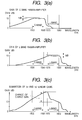
- Fig.3 is an explanatory illustration of a synthesized gain of a Raman amplifier.
- Fig.3(a) shows how both wavelength and intensity of pump lasers are adjusted so as to flatten the gain at 10dB in a pre-installed C-band, for example, the gain ripple is less than 1 dB.
- Fig.3(b) shows an example in which the wavelengths of the pump laser sources is shifted to the long wavelength side and set so as to flatten the gain in the L-band, as well.
- Fig.3(c) shows the synthesized gain of Fig.3(a) and Fig.3(b), in which pump laser sources in Fig.3(b) are simply added to the pump laser sources in Fig.3(a).
- Fig.3(c) shows a simple example in which it is assumed that gains are added up linearly. Even in such a case, each of the gains in Fig.3(a) and Fig.3(b) is extended from a band into another band, so that the gains are synthesized and the result is shaped as shown in Fig.3 (c).
- the gain of the C-band in which an optical signal is already transmitted changes by about 10 dB in maximum, thereby the optical signal might be degraded significantly.
- the gain band becomes uneven at the L-band side, so that the gain changes significantly at a wavelength around 1570nm and signal transmission is disabled.
- wavelength-multiplexed Raman pump lasers often interact each other due to the Raman effect in an actual Raman amplifier. Thus, gains are synthesized non-linearly and this makes it more difficult to add on pump lasers.
- the optical signal intensity changes significantly.
- the optical signal intensity increases so as to increase the non-linearity effect of the optical fiber, thereby the signal transmission property is degraded.
- Some of the wavelength-multiplexed signals are extremely amplified, so that the gains of other signals are reduced and the S/N ratio of each signal is degraded. It is also expected that the signal intensity change causes the allowable input range of a receiver to be exceeded, thereby the receiver is damaged, or the receiver automatic-gain control (AGC) circuit could not track an abrupt power change at a pump laser add-on time, resulting in transmission errors.
- AGC automatic-gain control
- the band-expanding method of the present invention for optical amplifiers expands an amplification band for optical amplifiers so as to amplify an optical signal in a second transmission band at a predetermined gain characteristic with use of an optical amplifier having a first pump laser source used to amplify an optical signal in a first transmission band, which is different from the second transmission band.
- the band-expanding method of the present invention comprises: a first step of adding on a second pump laser source separately from the first pump laser source, and a second step of controlling both of the first and second pump laser sources after the processing in the first step so that the first and second transmission bands have a predetermined gain characteristic respectively.
- the first pump laser source may not necessarily be a single pump laser, it may be a plurarity of laser sources; Similarly the second pump laser source may be a plurarity of laser sources. Said second pump laser source is added on in two ways; in one way, a second pump laser source is connected physically and in the other way, a pump laser source that is not turned on is prepared beforehand, then it is turned on (activated).
- each optical amplifier can be improved especially when the distributed Raman amplifier is used together with such lumped optical amplifier as a rare-earth doped optical fiber amplifier and a semiconductor amplifier.
- the output intensity values of some or all the pre-installed (the first pump laser sources) and the add-on pump laser sources (the second pump laser sources) are changed simultaneously when pump laser sources to be added on are turned on in the second step so as to prevent transmission signals from degradation in the add-on transition state of the second pump laser sources.
- the degradation of the optical signal in the pre-installed band caused by the change of the signal gain and the signal power during the band add-on process can be suppressed as follows; the pump powers are carefully controlled at each instance from the start state through the transition state to the end state, so that the total optical gain characteristic of the pre-installed band and the add-on band matches the specified gain profile, for example, the gain of the pre-installed band is unchanged through all the states from the start to the end.
- the method for setting a pump laser intensity in a transition state can be realized easily, for example, when the ratio between output intensities before and after the add-on or the ratio of each wavelength to the pump laser output intensity is changed approximately linearly with respect to the time so as to shift the state before the add-on to the state after the add-on. This is also effective even when pump lasers interact each other to some degree.
- the optical amplifier of the present invention includes a Raman amplifier having a first pump laser source used to amplify an optical signal in a first transmission band (an amplification band before the add-on) and means for adding on a second pump laser source used to amplify an optical signal in a second transmission band (amplification band after the add-on) with use of the above Raman amplifier.
- the second transmission band is different from the first transmission band.
- the optical amplifier is configured controllably so as to obtain the gains of the first and second transmission bands described above as predetermined gain characteristics.
- the means for adding on the above second pump laser includes a state in which the above second pump laser source is connected to a distributed Raman amplifier and inactive electrically.
- the means also includes setting means for controlling either wavelength or intensity of the above first and second pump laser sources.
- the present invention is especially effective in a distributed optical amplifier used as amplifying means of optical signals.
- the distributed optical amplifier employs the distributed Raman amplification that uses an optical fiber transmission line as an amplification medium.
- the present invention can prevent optical signals in pre-installed bands from intensity changes by setting the amplification gain or intensity of each optical signal in pre-installed bands to an approximately fixed value before and after the add-on of a pump laser source. Consequently, it is possible to prevent transmission of optical signals from degradation caused by the optical fiber non-linearity effect and S/N degradation, as well as receivers from deviation of the input ranges, damages, etc. For example, it is possible to prevent the items from significant degradation by suppressing gain/light intensity changes under 2 dB.
- the output intensity values, as well as the ratio of output intensity values of those pre-installed and add-on pump laser sources before, after the add-on , or in add-on transition state may be stored as electronic information or reference voltages in the apparatus or obtained from external with use of a monitor signal, header information, etc. They may also be written as electronic information when each of the above pump laser sources is added on or the apparatus may be configured so as to receive those information items from the reference voltage source or the memory in the add-on module.
- the apparatus may be configured so as to have a variable gain equalizer for controlling the gain or the gain shape of each of the wavelength bands in which pre-installed optical signals are transmitted in order to hold the gain or intensity of each pre-installed optical signal fixedly before, after the add-on or in add-on transition state.
- Fig.1 is a block diagram of an optical amplifier in the first embodiment of the present invention.
- This first embodiment is for a block diagram of an optical repeater 100 provided with a distributed Raman-amplifier.
- wavelength multiplexed optical signals 101 are transmitted in an optical fiber transmission line 102-1, amplified in an optical repeater 100, and output to an optical fiber transmission line 102-2.
- This optical amplification employs two amplification methods: distributed Raman amplification caused in the optical transmission line 102 by a backward Raman pump laser 113 entered from a Raman pump multiplexer 103; and amplification by such a lumped optical amplifier 109 as an EDFA.
- Raman pump laser source pre-installed Raman pump laser sources 111-1 and 111-2 having different wavelengths from each other are disposed before the band-expanding.
- the wavelength of the lasers output from those sources 111-1 and 111-2 are multiplexed in a wavelength multiplexer 110, then the multiplexed laser is output to an optical fiber transmission line 102-1 by a Raman pump multiplexer 103.
- the wavelenth multiplexer 110 is connected to a turned-off (inactive) pump laser source 112 via a connection port 114-1.
- the laser source 112 is prepared for band-expanding.
- the wavelength multiplexer 110 is also provided with a port 114-2 used to connect another pump laser source.
- the output intensity values of the Raman pump laser sources 111-1 and 111-2 are adjusted to the characteristic of the optical fiber transmission line 102-1, which is a gain medium, thereby they are controlled so that the gain characteristic of each signal light in pre-installed bands, that is, before band add-on and after band add-on becomes flat.
- the gain shape that is, the shape of the characteristic chart denoting the relationship between wavelength and gain is set so as to be inclined intentionally according to the characteristic of the repeater 100 or controlled automatically in some cases.
- the number of pre-installed pump laser sources is not limited, the number of pump laser sources is set so as to reduce the cost and to be enabled to flatten only some of wavelenth bands (pre-installed wavelenth bands).
- the number of pump laser sources to be added on is not limited; it is possible to add on a plurality of laser sources having different wavelenths from each another at the same time.
- the pump laser source 112 When an amplification band is added on, the pump laser source 112 is turned on or a pump laser source which is added to the port 114-2 is turned on. As a result, a gain arises from the new band, but a gain change also occurs even in each pre-installed wave band.
- the output intensity of each of the pre-installed pump laser sources 111-1 and 111-2 is changed, both gain and intensity of each signal light in the pre-installed band are maintained fixedly even after the pump laser source 112 is turned on.
- the pump laser source 112 When the pump laser source 112 is added on, a new wavelength optical signal can also be added on. However, because the new wavelength optical signal is not used yet for transmitting optical information, no problem arises as to whether the addition is done before or after the pump laser source is turned on.
- the Raman pump multiplexer 103 shown in Fig. 1 is just required to multiplex pump laser sources; it may not necessarily be a wavelength multiplexer.
- the wavelength multiplexer may be, for example, an optical coupler, an optical circulator, or the like that has no wavelength dependency, although the loss may increase.
- a backward pumping method that pumps each signal light from the downstream it may be replaced with a forward pumping method that pumps each signal light from the upstream or both pumping methods may be employed together.
- a semiconductor laser is widely used as a pump laser, but another laser such as a solid laser, an optical fiber ring laser may also be used.
- the pump laser source add-on port 114 may be an optical fiber connector, means for splicing an optical fiber strand, or means for coupling an optical signal collimated in the air with another with use of a lens system.
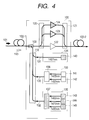
- Fig.4 shows a block diagram of an optical amplifier in the second embodiment of the present invention.
- an EDFA that is a lumped optical amplifier and a distributed Raman amplifier are used as gain media and the configuration of the second embodiment can add on an EDFA device and a Raman amplification pump laser source.
- the C-band is divided into two EDFAs; an EDFA with a short-wavelength side Blue-band (1530 to 1542nm) and an EDFA with a long wavelength side Red-band (1548 to 1560nm).
- the configuration is further enabled to add on an L-band EDFA therein.
- Red-band EDFA 122 In the initial state in which no add-on pump laser source is connected, only a Red-band EDFA 122 is disposed as a lumped optical amplifier and only a Red-band pump laser source unit 133 is disposed as a Raman pump laser source.
- the unit 133 incorporates a 1435nm pump laser source 141 and a 1455nm pump laser source 142 therein.
- the output lasers from the two pump laser sources 141 and 142 are multiplexed by a Raman pump multiplexer 136 in the unit 133.
- the multiplexed laser is then entered to a wavelength multiplexer 110 via a pump laser port 130.
- the optical repeater 100 amplifies the optical signal in the 12nm band of the Red-band.
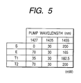
- the output intensity values of both Raman pump laser sources 141 and 142 are set to the values shown in the field S (before add-on) in Fig.5.
- the output intensity of the 1435nm pump laser source 141 is 30mW and the output intensity of the 1455nm pump laser source 142 is 200mW.
- the output intensity of the 1427nm pump laser source 140 is zero, since it is not connected yet or it is not turned on (inactive).
- the combination of the output intensity values shown in Fig.5 is just an example; it is varied significantly according to the type of the subject optical fiber, the subject wavelength and the number of pump lasers, and the subject wavelength band.
- a Blue-band EDFA 123 and a Blue-band add-on Raman pump laser source unit 134 are added on.
- the unit 134 incorporates a 1427nm pump laser source 140 therein and the output laser from the laser source 140 is entered to a wavelength multiplexer 110 via the pump laser source add-on port 131.
- the C-band can be amplified just by one EDFA. In this case, there is no need to divide/add on any EDFAs while it is needed in the EDFA 123/124.
- Fig.6 shows the gain characteristic of the embodiment shown in Fig.5.
- S denotes a Raman gain characteristic before the pump laser source unit 134 is added on. In this case, refer to the S line shown in Fig.5, as well.
- the pump laser intensity is set here so as to flatten the Red-band gain (9dB). Because the number of pump laser sources/wavelengths is not enough in this case, the Blue-band gain is not flattened; about 2 dB is lower than the Red-band one around 1530nm.
- the curve E denotes a gain characteristic assumed after the Blue-band add-on pump laser source unit 134 is added on.
- the output of the added-on 1427nm pump laser source 140 is set to 70mW and the output of the 1455nm pump laser source 142 is reduced to 165mW here.
- the same 9 dB gain is also obtained in the Blue-band by controlling the outputs of the pump laser sources and the Red-band gain is almost unchanged both before and after the add-on of the 1427nm pump laser source 140.
- the curve T2 denotes a gain characteristic assumed when the output laser intensity of the pre-installed pump laser source 133 is unchanged and the new 1427nm pump laser source 140 is turned on. Also refer to the T2 line shown in Fig.5, as well in this case.
- the Red-band gain is increased by 2 dB in maximum.
- a gain slope/gain tilt might appear. While the Raman gain in this example is kept flat, a gain slope/gain tilt appears in the Raman gain sometimes after the add-on process. Such a gain slope/gain tilt often causes SN degradation for optical signals having a less gain wavelength respectively and transmission degradation for optical signals having a large gain wavelength respectively due to the non-linearity phenomenon of large gain wavelengths. Because the Red-band is already used for transmitting customer information signals, the signal degradation will cut off information transmission services for those customers and become a serious problem.
- the gain change in each of the pre-installed wavelength bands can be suppressed as described above.
- the gain time constant is as fast as a picosecond order
- the gain change in a transition state in an add-on process becomes very important.
- the Raman gain follows the change immediately. Therefore, pre-installed optical signals of the pump laser intensity might be degraded unless it is assured that the gain in each of the pre-installed bands is flattened during a whole transition state.
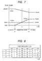
- Fig.7 shows a relationship between time and pump laser intensity so as to describe a controlling method for pump laser intensity by giving consideration to the state of transition to the add-on of the above pump laser source unit.
- controlling of changes of all the pump laser intensity values at the time A is started in the transition state from the state S before the add-on of the pump laser source unit to the state E after the add-on so as to change the light intensity linearly with respect to the time, thereby terminating the controlling of the changes of all the pump laser intensity values at the time B (controlling with time).
- the 1427nm pump laser intensity 0mW at the time A is increased to 30mW at the time B while the 1455nm pump laser intensity 200mW at the time A is reduced to 165mW at the time B.
- a Raman pump gain is a sum of the gain of each pump laser
- the practical gain in each transition state can be kept flat enough even by the simple controlling. This is especially effective when pump lasers do not interact each other so much.
- the intensity or the gain shape by the pump laser becomes like that of the characteristic T1 at the time T1 as shown in Fig.5 and Fig.6.
- the characteristic T1 denotes a gain just between those of the characteristics S and E in the Blue-band area and almost unchanged from those of both S and E in the Red-band.
- the gain in each of the pre-installed bands is not changed in any transition state, thereby optical signals are prevented from degradation.
- the pump laser source unit 135 incorporates a 1462nm pump laser source 143, a 1470nm pump laser source 144, and a 1490nm pump laser source 145 therein.
- the output laser from the unit 135 is multiplexed each other by a wavelenth multiplexer 137.
- the multiplexed laser is then entered to a wavelenth multiplexer 110 via a pump laser source add-on port 132.
- the wavelenth multiplexer 137 is omissible.
- the pump laser of each wavelength may be entered to the wavelenth multiplexer 110 independently of others via an add-on port specific to the wavelength.
- the configurations of the wavelenth multiplexer 110 and 103 are not limited only to those in this embodiment; the configurations may be varied freely, for example, each pump laser is led into an optical fiber transmission line via a wavelenth multiplexer specific to the pump laser.
- Figs.8 and 9 show the output intensity and the gain characteristic of a Raman pump laser source before and after the L-band is added on.
- the characteristic E after the Blue-band is added on as shown in Figs. 5 - 7, is changed to the characteristic S assumed before the L-band is added on.
- the output intensity values of the 1462nm, 1470nm, and 1490nm pump lasers to be added on are all zero just like that of the characteristic S shown in Fig.8.
- the gain curve S in Fig.9 the L-band generates just about 2 dB gain.
- the six pump laser output intensity values are adjusted to those in the state E after the add-on in Fig.8, the gain curve is set just like the characteristic E line shown in Fig.9.
- the configuration may also include a pump laser source whose power becomes zero after the add-on. Even in this embodiment, the gain change in the C-band in which a pre-installed optical signal is transmitted is suppressed under 0.5 dB, thereby it is possible to flatten the gain even in the L-band added on together with the C-band.
- the characteristic T2 line shown in Figs.8 and 9 denotes an example in which a new pump laser source is added on without the adjustment of preinstalled pump laser output intensity values.
- an L-band pump laser source generates a large gain even in the C-band, for example, the gain to be generated in the 1560nm pump laser source becomes as large as 3 dB just like that of the characteristic T2 shown in Fig.9.
- the gain change might further become large.
- a gain change more than 2 dB occurs even in the L-band, thereby the gain change in the band is shaped so as not to be compensated so easily.
- Those gains cause transmission degradation as described above, so that the effect of the present invention can be confirmed apparently in the characteristic E after the add-on.
- Fig.10 shows the transition gain characteristic in another embodiment of the present invention, in which consideration is given to each transition state. Also in this embodiment, controlling is started at the time A for all the pump lasers. Each laser intensity is changed linearly with time and controlling for all the pump lasers is terminated at the time B. Although the number of pump lasers increases in this embodiment, the control method is unchanged. For example, the intensity or gain shape by pump lasers at the time T1 is shaped just like that of the characteristic T1 line shown in Figs.8 and 9.
- the gain curve T1 shown in Fig.9 denotes an intermediate gain between those of the characteristics S and E in the new L-band area and it is almost the same as those of the characteristics S and E in the C-band area.
- a Raman gain band is wide, so that pump lasers interact each other. For example, a change of about 2dB is observed in the gain of the 1490nm pump laser according to whether or not another wavelength pump laser exists.
- the wavelength of the 1490nm pump laser is the longest. It is thus confirmed that the present invention is also effective even when pump lasers interact to some degree each other such way.
- Fig.11 shows a block diagram of an optical amplifier in the third embodiment of the present invention.
- the configuration of this third embodiment includes an optical repeater and a pump laser source controller 150 used to control the laser intensity of each added-on pump laser source.
- a pump laser intensity table 151 is disposed in the pump laser source controller 150.
- the table 151 stores the laser intensity values of each pump laser source before and after its add-on.
- This table 151 stores pump laser intensity values of each pump laser source before and after it is added on in a semiconductor memory and/or a disk drive by a software program and/or set in a hardware device, that is, as a reference voltage, a voltage dividing circuit using registers, etc.
- the pump laser source controller 150 checks whether or not the add-on pump laser source 112 exists, then starts setting of a pump laser intensity value. Concretely, the controller 150 refers to the pump laser source table 151 so as to read the laser intensity value of each pump laser source before and after the add-on, then calculates the pump laser intensity at each time in the transition state so as to set each pump laser intensity until the added-on laser intensity is reached in a predetermined time. As shown in Figs.7 and 10, when the pump laser intensity changes monotonously at each time in the transition state, the value is merely interpolated linearly. Therefore, it is so easy.
- the band upgrading start signal 152 is not necessarily needed. Instead of the signal 152, it is also possible to detect add-on of a pump laser source, optical fiber connection, etc. internally, thereby adding on a band, that is, setting a pump laser intensity automatically. A manual button provided on the subject device, a remote command issued by a monitor signal, or the like may be used as the band upgrading start signal 152.
- Values to be stored in the pump laser intensity table 151 may not only be those before/after the add-on, but also curves of pump laser intensity values to be changed with time in transition states and stored in tables, as functions, etc. beforehand. This will be effective specially when the inter-pump-laser Raman interaction is strong, when a complicated interpolation calculation is needed, etc.
- the output of a pump laser source before and after the add-on may be transferred from another site, an optical repeater station, etc. as part of monitored information without storing it in the repeater. It is also possible to provide a computer inside an optical amplifier so as to calculate pump laser intensity values, compensate values in tables with use of the computer. In this case, an injected laser intensity, etc. may be used to give consideration to the saturation, etc. in a Raman amplifier, the type and loss of the optical fiber transmission line 102-1 to be used as an amplification medium. The pump laser intensity can thus be calculated more accurately.
- Fig.12 shows a block diagram of the pump laser source controller 150 shown in Fig.11.
- the micro controller 153 receiving an add-on start signal 152, reads the pump laser intensity table 151 stored in such a non-volatile memory as a flash memory under the control of an inner program.
- the micro controller 153 then calculates the intensity of each pump laser source for a fixed time so as to set the result for an A/D converter 154.
- the output voltage of the A/D converter 154 is converted to a current by one of laser drive circuits 155-1 to 4 and used to drive a semiconductor laser, which is a pump laser source.
- the current is then converted to a pump laser.
- Fig.13 shows a block diagram of an optical amplifier in the fourth embodiment of the present invention.
- an add-on pump laser source controller 163 is built in an add-on pump laser source unit 160 so as to control each pump laser more precisely.
- a pump laser source information table 162 provided in the controller 163 stores information of each device, such as a relationship between laser drive current and output intensity of each of pump laser sources 112-1 and 112-2 to be added on, the loss information of a wavelenth multiplexer 164, etc. Those information items are combined so as to set a pump laser intensity value more precisely.
- the pump laser source information table 162 should preferably be stored in such a rewritable non-volatile medium as a flash memory so that it is used more effectively.
- the pump laser source information table 162 can also store output laser intensity set values of all or some of the added-on pump laser sources. In this case, it is possible to change the set values of the wavelength and output intensity of the pump laser sources 112-1 and 112-2 after the repeater 100 is installed, thereby the system configuration becomes more flexible.
- the pump laser source controller 150 and the add-on pump laser source controller 163 are connected to each other via an internal information path 165, so that information in the information tables in them, as well as presence of an add-on unit, each unit state, an add-on timing, etc. can be exchanged between those controllers 150 and 163.
- the controllers 150 and 163 are omissible, however. Only the pump laser source information table and the A/D converter may be disposed at the added-on unit side.
- Fig.14 shows a block diagram of an optical amplifier in the fifth embodiment of the present invention.
- the present invention applies to a system for controlling the Raman amplification gain slope/tilt automatically.
- a Blue-band pump laser source is added on for a pre-installed Red-band Raman amplifier.
- the optical repeater 100 observes the level of the ASE (Amplified Spontaneous Emission) emitted from each optical amplifier so as to find the Raman amplification gain, then controls so as to flatten the gain with use of the result.
- the gain shape to be controlled here may not necessarily be flat; for example, it may be suppressing of a tilt of a wavelength-multiplexed signal with use of a Raman gain, giving the signal a specific gain slope/tilt internally.
- the present invention can apply to any of those cases, since a gain change of an pre-installed optical signal caused by add-on of a new pump laser source often degrades the signal transmission.
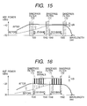
- the optical branch 170 takes out part of the wavelength-multiplexed signal and leads it into three optical band-pass filters 171 to 173 respectively.
- the transmission bands of those three band-pass filters are, as shown in Fig.15, an intermediate portion between the Blue-band and the Red-band, the long wavelength side of the Red-band, and the short wavelength side of the Blue-band, each of them are set outside the optical signal band. Consequently, only the ASE lights in those bands are led into the photo detectors 174-1 to 174-3, thereby the intensity measurement results are sent to the pump laser source controller 150.
- the outputs from the optical band-pass filters 171 and 172 provided at both sides of the Red-band are controlled so as to be fixed to a certain ratio respectively, thereby controlling the Raman gain flat.
- an add- on Raman pump laser source 112 When the Blue-band is added on, an add- on Raman pump laser source 112 is connected and the output of an optical band-pass filter 173 at the Blue-band short wavelength side is added for starting the controlling.
- controlling is done so that a predetermined ratio is kept between the output of the optical band-pass filter 173 that denotes the gain of a newly added-on band and the output of another band-pass filter while the output levels of the optical band-pass filters 171 and 172 that denote a Raman gain in the Red-band respectively are kept unchanged.
- a pump laser source can thus be added on while the gain of each optical signal in the pre-installed bands is kept fixedly.
- the thin line denotes a gain obtained before the add-on and the thick line denotes a gain obtained after the add-on.
- the ASE level is amplified almost in accordance with this gain, so that the controlling of the present invention is enabled.
- An ASE level is decided by a gain of an optical amplifier and a noise figure.
- the ASE level is changed by a wavelength significantly.
- the ASE intensity is the accumulation of the ASE noise from every optical repeater in the upstream. Therefore, the Raman gain to which a signal light subjected is not flattened even when the ASE level at both ends of a signal band is set equally.
- This problem can be solved, however, by flattening the Raman gain after weighting the output signal from each photo detector 174 with the NF characteristic of each optical amplifier in the pump laser source controller 150. More precisely, when the ASE level information observed in the nearest optical amplifier in the upstream is transmitted to each optical repeater in the downstream, the Raman gain can be observed at the minimum error.
- Fig.16 shows a graph of the gain characteristic for describing controlling of a Raman gain by observing the signal light level in the embodiment shown in Fig.14.
- the optical band-pass filters 171 to 173, as denoted by the dark portion in Fig.16, are set in the bands at the short wavelength side of the Red-band, the long wavelength side of the Red-band, and the short wavelength side of the Blue-band respectively so as to observe the optical signal intensity values.
- Each of those band-pass filters 171 to 173 is set so as to take out the signal light for one channel.
- the controlling method in this case is the same as that described with reference to Fig.15.
- the intensity values of the pre-installed Raman pump laser sources 111-1 and 111-2 are controlled before the add-on so that the optical output intensity of each of the optical band-pass filters 171 and 172, which are signal levels at both ends of the Red-band, becomes a predetermined intensity value.
- the Raman pump laser source 112 After the Raman pump laser source 112 is added on, the signal level is observed at the short wavelength side of the Blue-band and controlling is done so that a certain ratio is assumed between the signal level and the light intensity of the Red-band or so that a predetermined intensity value is assumed.
- the pre-installed Raman pump laser sources 111-2 and 111-3 are controlled so that the optical signal intensity values of the optical band-pass filters 171 and 172 take the same values as those assumed before the add-on, thereby the pre-installed Red-band signal intensity values are prevented from changes.
- the pre-installed Raman pump laser sources 111-2 and 111-3 are controlled even in the add-on process so that the output intensity of the add-on Raman pump laser source 112 increases gradually and the optical signal intensity values of the optical band-pass filters 171 and 172 take the same optical signal intensity values as those before the add-on continually, thereby preventing the transient transmission degradation in the add-on process.
- the gain changes are suppressed automatically in each pre-installed band at the add-on time and the gain shape of the new add-on band can be set to a predetermined one even when a significant Raman interaction occurs between the pump laser and another pump laser, the Raman gain is non-linear, and the gain shape in a transition state is difficult to estimate.
- the tilting of each signal light generated by the Raman effect among signal lights can be suppressed.
- more photo detectors may be added on and a spectrum analyzer, etc. may be used to control complicated gains. While only the Raman gain is observed in the above example, the gain observation point may be shifted, for example, behind the lumped constant optical amplifier 109 so that signal gain shapes including the gain of the lumped amplifer 109 are controlled.
- the present invention covers all of those cases where a new pump laser source is added on while changes of gains and intensity values of pre-installed signals are suppressed. This is also the same when the number of pump laser sources increases.
- controlling algorithm is not limited only to the above-described one; controlling may be complicated more by combining the controlling methods that the sum of pump laser powers is fixed, the level of each optical signal is fixed, etc., and by adding such information as the number of channels, received optical signal intensity values, etc. obtained, for example, from a monitor signal to the controlling.
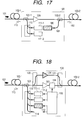
- Fig.17 shows a block diagram of an optical amplifier in the sixth embodiment of the present invention.
- a Raman pump multiplexer 103-2 is disposed at the output side of an optical repeater and a forward pump laser source add-on port 181 is provided for the optical amplifier.
- the pre-installed Raman pump laser sources 111-1 and 111-2 are used for backward pumping and the add-on Raman pump laser source 180 is used for forward pumping in this embodiment, the functions and the add-on method are almost the same as those in the above embodiments.
- This sixth embodiment has an advantage that Raman interaction among the pre-installed and add-on pump lasers are reduced more than in the above embodiments.
- Fig.18 shows a block diagram of an optical amplifier in the seventh embodiment of the present invention.
- a variable gain equalizer 184 is disposed just after a C-band EDFA 183, which is a pre-installed lumped optical amplifier.
- the pump laser source controller 150 in this embodiment controls the add-on Raman pump laser source 112 and the variable gain equalizer 184 together.
- the controller 150 cancels the change of the pre-installed C-band gain caused by the add-on pump laser source 112 that is turned on by changing the wavelength attenuation characteristic of the variable gain equalizer 184 so as to keep the C-band gain at a fixed value.
- the controlling method in this embodiment may be combined together with the controlling method for the pre-installed pump laser source 111.
- control methods to flatten either intensity of each signal laser or gain spectrum can apply to this embodiment. Consequently, it is possible to prevent gains from changes before, after, and in an add-on process even when no complicated controlling is done for gain shapes.
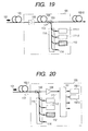
- Fig.19 shows a block diagram of an optical amplifier in the eighth embodiment of the present invention.
- the present invention applies to a lumped Raman amplifier.
- the gain medium in this embodiment is a Raman amplification fiber 185 for which high non-linearity fiber, dispersion compensation fiber (DCF), etc. are used.
- the Raman pump laser 113 is entered to the Raman amplification fiber 185 and blocked by an optical isolator 186, so that the laser 113 does not reach the optical fiber transmission line 102-1.
- the gain in each pre-installed wavelength band is affected by an added-on Raman pump laser source 112, so that the present invention can apply to the lumped Raman amplifier as it is.
- the amplifier 185 may also be used together with a lumped amplifier as an EDFA or a distributed Raman amplifier that uses a transmission line as a gain medium.
- Fig.20 shows a block diagram of an optical amplifier in the ninth embodiment of the present invention.
- the optical amplifier is used as a pre-amplifier of an optical receiving site 190.
- a signal wavelength demultiplexer 191 is disposed at the output side of the lumped optical amplifier 109 and branched optical signals are received by the optical receivers 191-1, 191-2, etc. at their corresponding channels.
- the application method and the add-on method of the present invention in this embodiment are the same as those of the optical repeater. Those methods of the present invention are also the same when the present invention applies to a transmitting site.
- the present invention is not limited only to those embodiments.
- Raman amplifiers are used as distributed optical amplifiers in the above embodiments
- the present invention can apply to any optical amplifiers that satisfy the following conditions; (1) a gain shape change occurs due to a pump laser wavelenth, (2) optical amplification media common to both new and add-on bands are used, and (3) the gain bands of both or one of pre-installed and add-on pump laser are overlapping to the other gain band, and gains in both bands are not independent of each other.
- Such optical amplifiers are the above-described distributed Raman amplifiers, as well as lumped constant Raman amplifiers, parametric optical amplifiers, optical amplifiers that employ the SBS (Stimulated Brillouin Scattering) method or the part of rare-earth doped optical fiber, respectively, and other many examples.
- the amplification optical fiber of a lumped Raman amplifier is used commonly to optical signals in all wavelength bands, the above conditions are satisfied, so that the pump laser add-on method of the present invention can apply to the amplifier as it is.
- the method can also apply to the fiber in the same way.
- the present invention can also apply to the rare-earth doped optical fiber when it has a plurality of pumping states and its gain shape changes significantly in accordance with the wavelength of each pump laser.
- the lumped optical amplifier in the above embodiments may be replaced with any of lumped optical amplifiers of other types.
- the EDFA may be replaced with any of another type of rare-earth doped optical fiber amplifier, semiconductor optical amplifier, lumped constant Raman amplifier, etc.
- the lumped optical amplifier part may be replaced with any optical amplifier that uses an independent gain medium for each of pre-installed and add-on bands or has no inter-band gain interaction, since an optical amplifier can be added on independently for each band.
- Lumped constant Raman amplifiers are concentrated in an optical amplifier with the use of such a comparatively high non-linear fiber as the dispersion compensation fiber (DCF), the dispersion shifted fiber (DSF), as a gain medium.
- DCF dispersion compensation fiber
- DSF dispersion shifted fiber
- the lumped constant Raman amplifier can change wavelength/band setting freely in accordance with the application purpose. While bands before add-on are distinguished from bands after add-on in the description of the above embodiments, the distinction is not always required actually.
- the portion that an information signal is transmitted before a pump laser is added on becomes "a pre-installed wavelength band" referred in the present invention and a wavelength portion in which a signal laser is transmitted after the add-on becomes "an add-on wavelength band” referred in the present invention respectively. Consequently, in the case of a method that a transmission band is expanded while the wavelength of a pump laser is added on one by one, the present invention can apply to the method.
- each of the pre-installed optical signals from changes of the signal intensity, degradation, as well as to prevent a receiver from damages even when a pump laser source is added on for a distributed Raman optical amplifier. It is also possible to flatten or shape the gain as desired even in an add-on band. It is also possible to prevent the gain in each pre-installed band from transient changes.
Landscapes
- Physics & Mathematics (AREA)
- Electromagnetism (AREA)
- Engineering & Computer Science (AREA)
- Computer Networks & Wireless Communication (AREA)
- Signal Processing (AREA)
- Optical Modulation, Optical Deflection, Nonlinear Optics, Optical Demodulation, Optical Logic Elements (AREA)
- Optical Communication System (AREA)
- Lasers (AREA)
Applications Claiming Priority (2)
| Application Number | Priority Date | Filing Date | Title |
|---|---|---|---|
| JP2001109361A JP4188573B2 (ja) | 2001-04-09 | 2001-04-09 | 光増幅器の増幅帯域拡大方法、光増幅器、及び増設ユニット |
| JP2001109361 | 2001-04-09 |
Publications (3)
| Publication Number | Publication Date |
|---|---|
| EP1249901A2 true EP1249901A2 (de) | 2002-10-16 |
| EP1249901A3 EP1249901A3 (de) | 2005-02-09 |
| EP1249901B1 EP1249901B1 (de) | 2008-04-02 |
Family
ID=18961313
Family Applications (1)
| Application Number | Title | Priority Date | Filing Date |
|---|---|---|---|
| EP01119778A Expired - Lifetime EP1249901B1 (de) | 2001-04-09 | 2001-08-28 | Verfahren zur Bandbreitenerweiterung für optische Verstärker und optische Übertragungseinrichtung |
Country Status (4)
| Country | Link |
|---|---|
| US (1) | US6587260B2 (de) |
| EP (1) | EP1249901B1 (de) |
| JP (1) | JP4188573B2 (de) |
| DE (1) | DE60133450T2 (de) |
Cited By (2)
| Publication number | Priority date | Publication date | Assignee | Title |
|---|---|---|---|---|
| EP1583186A1 (de) * | 2004-03-30 | 2005-10-05 | Fujitsu Limited | Optischer Verstärker und Methode zur Kontrolle eines Raman-Verstärkers |
| EP2682813A4 (de) * | 2011-03-04 | 2014-12-31 | Furukawa Electric Co Ltd | Optischer verstärker, optisches verstärkungssystem, wellenlängenwandler, verfahren zur optischen verstärkung und optisches kommunikationssystem |
Families Citing this family (21)
| Publication number | Priority date | Publication date | Assignee | Title |
|---|---|---|---|---|
| JP4541574B2 (ja) * | 2001-02-07 | 2010-09-08 | 富士通株式会社 | 光中継伝送システムおよび光中継伝送方法 |
| US6731425B1 (en) * | 2002-03-07 | 2004-05-04 | Cisco Technology, Inc. | Modular Raman pump double-multiplexer |
| US6992814B2 (en) * | 2002-06-17 | 2006-01-31 | Avanex Corporation | Wide-band raman amplifiers |
| JP3933550B2 (ja) * | 2002-07-15 | 2007-06-20 | 古河電気工業株式会社 | 増幅帯域拡張機能を有したラマン増幅励起用光源装置、これを用いたラマン増幅器、増幅帯域拡張設定方法およびそのプログラム |
| JP4184046B2 (ja) * | 2002-11-18 | 2008-11-19 | 富士通株式会社 | ラマン増幅器 |
| JP4532407B2 (ja) | 2003-02-27 | 2010-08-25 | 古河電気工業株式会社 | 波長多重励起ラマンアンプの制御装置、波長多重励起ラマンアンプ、およびその制御方法 |
| EP1469621B1 (de) * | 2003-04-14 | 2005-09-07 | Alcatel | Optischer Raman-Verstärker und Verfahren zur Pumpmodulation |
| US7181095B1 (en) | 2003-07-29 | 2007-02-20 | Cisco Technology, Inc. | Low loss, noise filtering multiplexer/demultiplexer for reconfigurable OADMs |
| JP2005123229A (ja) * | 2003-10-14 | 2005-05-12 | Nec Engineering Ltd | 光ファイバ増幅装置及びその制御方法 |
| US20050226622A1 (en) * | 2004-04-06 | 2005-10-13 | Kddi Submarine Cable Systems Inc. | Underwater repeater employing rare earth element doped fiber amplifier, Raman assist and optical pump source sparing |
| JP4298570B2 (ja) | 2004-04-13 | 2009-07-22 | 富士通株式会社 | 光ファイバ増幅器の制御方法および光伝送システム |
| US7916384B2 (en) * | 2006-05-02 | 2011-03-29 | At&T Intellectual Property Ii, L.P. | Feedback dynamic gain control for a WDM system employing multi wavelength pumped Raman fiber amplifiers |
| JP4973491B2 (ja) * | 2007-12-26 | 2012-07-11 | 富士通株式会社 | 光伝送装置および光通信システム |
| JP2009231526A (ja) * | 2008-03-24 | 2009-10-08 | Fujitsu Ltd | 半導体レーザの制御方法および半導体レーザの制御装置 |
| US20120002283A1 (en) * | 2010-06-30 | 2012-01-05 | Chongjin Xie | Method and apparatus for raman co-pumps |
| JP6132595B2 (ja) * | 2013-03-04 | 2017-05-24 | 三菱電機株式会社 | ラマン増幅器、光中継装置、光通信システム、ラマン増幅制御方法及びプログラム |
| US9762319B1 (en) * | 2015-09-29 | 2017-09-12 | Juniper Networks, Inc. | Real-time Raman gain monitoring |
| US10003168B1 (en) * | 2017-10-18 | 2018-06-19 | Luminar Technologies, Inc. | Fiber laser with free-space components |
| JP7077794B2 (ja) | 2018-06-04 | 2022-05-31 | 富士通株式会社 | ラマン光増幅器及びラマン光増幅方法 |
| KR102784283B1 (ko) * | 2021-03-17 | 2025-03-21 | 한국전자통신연구원 | 직접 변조 레이저를 이용한 테라헤르츠 신호 생성 장치 및 방법 |
| JP7810891B2 (ja) * | 2022-04-21 | 2026-02-04 | 1Finity株式会社 | ラマン増幅装置、ラマン増幅方法、及びラマン増幅システム |
Family Cites Families (17)
| Publication number | Priority date | Publication date | Assignee | Title |
|---|---|---|---|---|
| JPH09321701A (ja) * | 1996-05-31 | 1997-12-12 | Fujitsu Ltd | 光通信システム及び光増幅器 |
| US5920423A (en) * | 1997-12-05 | 1999-07-06 | Sdl, Inc. | Multiple pumped fiber amplifiers for WDM communication systems with adjustment for the amplifier signal gain bandwidth |
| EP1055299A2 (de) * | 1998-02-20 | 2000-11-29 | SDL, Inc. | Erweiterbare verstärkungsglättende faserverstärker für wellenlängenmultiplexbasierte anwendungen |
| US6600592B2 (en) * | 1998-03-24 | 2003-07-29 | Xtera Communications, Inc. | S+ band nonlinear polarization amplifiers |
| US6574037B2 (en) * | 1998-06-16 | 2003-06-03 | Xtera Communications, Inc. | All band amplifier |
| CA2335289C (en) * | 1998-06-16 | 2009-10-13 | Mohammed Nazrul Islam | Fiber-optic compensation for dispersion, gain tilt, and band pump nonlinearity |
| US6335820B1 (en) * | 1999-12-23 | 2002-01-01 | Xtera Communications, Inc. | Multi-stage optical amplifier and broadband communication system |
| US6344922B1 (en) * | 1998-07-21 | 2002-02-05 | Corvis Corporation | Optical signal varying devices |
| US6115174A (en) | 1998-07-21 | 2000-09-05 | Corvis Corporation | Optical signal varying devices |
| EP2306605B1 (de) * | 1998-07-23 | 2012-05-23 | The Furukawa Electric Co., Ltd. | Pumpeinheit für einen Ramanverstärker und Ramanverstärker, der dieselbe aufweist |
| US6611370B2 (en) * | 1999-07-23 | 2003-08-26 | The Furukawa Electric Co., Ltd. | Raman amplifier system, apparatus and method for identifying, obtaining and maintaining an arbitrary Raman amplification performance |
| US6313940B1 (en) * | 1999-12-31 | 2001-11-06 | Lucent Technologies Inc. | System based control of optical amplifier transmission functions |
| US6310716B1 (en) * | 2000-08-18 | 2001-10-30 | Corning Incorporated | Amplifier system with a discrete Raman fiber amplifier module |
| US6452715B1 (en) * | 2000-08-29 | 2002-09-17 | Ciena Corporation | Method and apparatus for determining a fiber plant gain transfer function and utilizing same to control distributed gain |
| US6452716B1 (en) * | 2000-10-05 | 2002-09-17 | Nortel Networks Limited | Amplitude modulation of a pump laser signal in a distributed raman amplifier |
| US6424458B1 (en) * | 2000-12-22 | 2002-07-23 | Ciena Corporation | Optical pre-amplifier apparatus and method for receiver performing windowed and gain change rate control |
| US6456426B1 (en) * | 2001-06-28 | 2002-09-24 | Onetta, Inc. | Raman amplifiers with modulated pumps |
-
2001
- 2001-04-09 JP JP2001109361A patent/JP4188573B2/ja not_active Expired - Fee Related
- 2001-08-24 US US09/935,543 patent/US6587260B2/en not_active Expired - Lifetime
- 2001-08-28 EP EP01119778A patent/EP1249901B1/de not_active Expired - Lifetime
- 2001-08-28 DE DE60133450T patent/DE60133450T2/de not_active Expired - Lifetime
Cited By (4)
| Publication number | Priority date | Publication date | Assignee | Title |
|---|---|---|---|---|
| EP1583186A1 (de) * | 2004-03-30 | 2005-10-05 | Fujitsu Limited | Optischer Verstärker und Methode zur Kontrolle eines Raman-Verstärkers |
| US7095553B2 (en) | 2004-03-30 | 2006-08-22 | Fujitsu Limited | Optical amplifier and controlling method for Raman amplifier |
| EP2682813A4 (de) * | 2011-03-04 | 2014-12-31 | Furukawa Electric Co Ltd | Optischer verstärker, optisches verstärkungssystem, wellenlängenwandler, verfahren zur optischen verstärkung und optisches kommunikationssystem |
| US9270076B2 (en) | 2011-03-04 | 2016-02-23 | Furukawa Electric Co., Ltd. | Optical amplifier, optical amplifying system, wavelength converter, optical amplification method, and optical communication system |
Also Published As
| Publication number | Publication date |
|---|---|
| JP2002303896A (ja) | 2002-10-18 |
| DE60133450D1 (de) | 2008-05-15 |
| JP4188573B2 (ja) | 2008-11-26 |
| US6587260B2 (en) | 2003-07-01 |
| US20020145796A1 (en) | 2002-10-10 |
| EP1249901A3 (de) | 2005-02-09 |
| EP1249901B1 (de) | 2008-04-02 |
| DE60133450T2 (de) | 2009-05-07 |
Similar Documents
| Publication | Publication Date | Title |
|---|---|---|
| EP1249901B1 (de) | Verfahren zur Bandbreitenerweiterung für optische Verstärker und optische Übertragungseinrichtung | |
| US6292289B1 (en) | Method, device, and system for transmitting a supervisory optical signal | |
| JP4565794B2 (ja) | 光増幅装置および光通信システム | |
| EP0897205B1 (de) | Verfahren und Vorrichtung zur optischen Verstärkung und System, das eine solche Vorrichtung umfasst | |
| US6865016B2 (en) | Controller which controls a variable optical attenuator to control the power level of a wavelength-multiplexed optical signal when the number of channels are varied | |
| EP2209232B1 (de) | Verstärkungs- und Pegelregelungen von optischen Verstärkern in Kaskade | |
| US6288836B1 (en) | Optical amplifier and optical communication system having the optical amplifier | |
| US6480329B2 (en) | Multi-wavelength light amplifier | |
| EP1033834A2 (de) | Optischer Verstärker und Optisches Übertragungssystem für Wellenlängenmultiplexübertragung | |
| EP0910139A2 (de) | Optischer Verstärker und damit ausgestattetes optisches Nachrichtenübertragungssystem | |
| KR20010042232A (ko) | 이득 평탄화 필터를 가진 광섬유 증폭기 | |
| EP1073166A2 (de) | Faseroptischer L-Band-Verstärker mit Rückkopplungsschleife | |
| US7145718B2 (en) | Control method of optical fiber amplifier and optical transmission system | |
| CA2365544A1 (en) | High order fiber raman amplifiers | |
| US20030063850A1 (en) | Method and device for optical amplification | |
| EP1237238A2 (de) | Optischer Faserverstärker mit stabilisierter Verstärkung | |
| JP3338007B2 (ja) | 光増幅器及び波長多重光通信システム | |
| JP2003298162A (ja) | 光増幅装置 | |
| KR20170013059A (ko) | 소형화된 광섬유 증폭기 |
Legal Events
| Date | Code | Title | Description |
|---|---|---|---|
| PUAI | Public reference made under article 153(3) epc to a published international application that has entered the european phase |
Free format text: ORIGINAL CODE: 0009012 |
|
| AK | Designated contracting states |
Kind code of ref document: A2 Designated state(s): AT BE CH CY DE DK ES FI FR GB GR IE IT LI LU MC NL PT SE TR |
|
| AX | Request for extension of the european patent |
Free format text: AL;LT;LV;MK;RO;SI |
|
| PUAL | Search report despatched |
Free format text: ORIGINAL CODE: 0009013 |
|
| AK | Designated contracting states |
Kind code of ref document: A3 Designated state(s): AT BE CH CY DE DK ES FI FR GB GR IE IT LI LU MC NL PT SE TR |
|
| AX | Request for extension of the european patent |
Extension state: AL LT LV MK RO SI |
|
| 17P | Request for examination filed |
Effective date: 20050426 |
|
| AKX | Designation fees paid |
Designated state(s): DE FR GB |
|
| 17Q | First examination report despatched |
Effective date: 20060620 |
|
| GRAP | Despatch of communication of intention to grant a patent |
Free format text: ORIGINAL CODE: EPIDOSNIGR1 |
|
| GRAS | Grant fee paid |
Free format text: ORIGINAL CODE: EPIDOSNIGR3 |
|
| GRAA | (expected) grant |
Free format text: ORIGINAL CODE: 0009210 |
|
| RIN1 | Information on inventor provided before grant (corrected) |
Inventor name: TAKEYARI, RYOJI,C Inventor name: KIKUCHI, NOBUHIKO,C |
|
| RAP1 | Party data changed (applicant data changed or rights of an application transferred) |
Owner name: HITACHI, LTD. |
|
| AK | Designated contracting states |
Kind code of ref document: B1 Designated state(s): DE FR GB |
|
| REG | Reference to a national code |
Ref country code: GB Ref legal event code: FG4D |
|
| REF | Corresponds to: |
Ref document number: 60133450 Country of ref document: DE Date of ref document: 20080515 Kind code of ref document: P |
|
| ET | Fr: translation filed | ||
| PLBE | No opposition filed within time limit |
Free format text: ORIGINAL CODE: 0009261 |
|
| STAA | Information on the status of an ep patent application or granted ep patent |
Free format text: STATUS: NO OPPOSITION FILED WITHIN TIME LIMIT |
|
| 26N | No opposition filed |
Effective date: 20090106 |
|
| PGFP | Annual fee paid to national office [announced via postgrant information from national office to epo] |
Ref country code: GB Payment date: 20120822 Year of fee payment: 12 |
|
| PGFP | Annual fee paid to national office [announced via postgrant information from national office to epo] |
Ref country code: FR Payment date: 20120823 Year of fee payment: 12 Ref country code: DE Payment date: 20120822 Year of fee payment: 12 |
|
| GBPC | Gb: european patent ceased through non-payment of renewal fee |
Effective date: 20130828 |
|
| PG25 | Lapsed in a contracting state [announced via postgrant information from national office to epo] |
Ref country code: DE Free format text: LAPSE BECAUSE OF NON-PAYMENT OF DUE FEES Effective date: 20140301 |
|
| REG | Reference to a national code |
Ref country code: FR Ref legal event code: ST Effective date: 20140430 |
|
| REG | Reference to a national code |
Ref country code: DE Ref legal event code: R119 Ref document number: 60133450 Country of ref document: DE Effective date: 20140301 |
|
| PG25 | Lapsed in a contracting state [announced via postgrant information from national office to epo] |
Ref country code: GB Free format text: LAPSE BECAUSE OF NON-PAYMENT OF DUE FEES Effective date: 20130828 |
|
| PG25 | Lapsed in a contracting state [announced via postgrant information from national office to epo] |
Ref country code: FR Free format text: LAPSE BECAUSE OF NON-PAYMENT OF DUE FEES Effective date: 20130902 |