EP1249852A2 - Installationsgerät - Google Patents
Installationsgerät Download PDFInfo
- Publication number
- EP1249852A2 EP1249852A2 EP02007824A EP02007824A EP1249852A2 EP 1249852 A2 EP1249852 A2 EP 1249852A2 EP 02007824 A EP02007824 A EP 02007824A EP 02007824 A EP02007824 A EP 02007824A EP 1249852 A2 EP1249852 A2 EP 1249852A2
- Authority
- EP
- European Patent Office
- Prior art keywords
- switching device
- actuator
- installation switching
- acts
- point
- Prior art date
- Legal status (The legal status is an assumption and is not a legal conclusion. Google has not performed a legal analysis and makes no representation as to the accuracy of the status listed.)
- Withdrawn
Links
Images



Classifications
-
- H—ELECTRICITY
- H01—ELECTRIC ELEMENTS
- H01H—ELECTRIC SWITCHES; RELAYS; SELECTORS; EMERGENCY PROTECTIVE DEVICES
- H01H71/00—Details of the protective switches or relays covered by groups H01H73/00 - H01H83/00
- H01H71/10—Operating or release mechanisms
- H01H71/12—Automatic release mechanisms with or without manual release
- H01H71/127—Automatic release mechanisms with or without manual release using piezoelectric, electrostrictive or magnetostrictive trip units
-
- H—ELECTRICITY
- H01—ELECTRIC ELEMENTS
- H01H—ELECTRIC SWITCHES; RELAYS; SELECTORS; EMERGENCY PROTECTIVE DEVICES
- H01H71/00—Details of the protective switches or relays covered by groups H01H73/00 - H01H83/00
- H01H71/10—Operating or release mechanisms
- H01H71/12—Automatic release mechanisms with or without manual release
- H01H71/123—Automatic release mechanisms with or without manual release using a solid-state trip unit
-
- H—ELECTRICITY
- H01—ELECTRIC ELEMENTS
- H01H—ELECTRIC SWITCHES; RELAYS; SELECTORS; EMERGENCY PROTECTIVE DEVICES
- H01H83/00—Protective switches, e.g. circuit-breaking switches, or protective relays operated by abnormal electrical conditions otherwise than solely by excess current
- H01H83/20—Protective switches, e.g. circuit-breaking switches, or protective relays operated by abnormal electrical conditions otherwise than solely by excess current operated by excess current as well as by some other abnormal electrical condition
- H01H83/22—Protective switches, e.g. circuit-breaking switches, or protective relays operated by abnormal electrical conditions otherwise than solely by excess current operated by excess current as well as by some other abnormal electrical condition the other condition being imbalance of two or more currents or voltages
- H01H83/223—Protective switches, e.g. circuit-breaking switches, or protective relays operated by abnormal electrical conditions otherwise than solely by excess current operated by excess current as well as by some other abnormal electrical condition the other condition being imbalance of two or more currents or voltages with bimetal elements
Definitions
- the invention relates to an installation switching device according to the preamble of the claim 1.
- Such an installation device is commercially available and is known as a circuit breaker.
- Such an installation switching device is often a residual current device assigned, the residual current device either as a residual current circuit breaker is assigned to the circuit breaker or as a residual current detection device is inside the housing of the circuit breaker, wherein the size of the housing must be adapted to it.
- the trigger is an element made of an electrostrictive Material that changes shape when tension occurs.
- Such an element here is a piezo element which is connected to a latching point of a Switch lock of the residual current circuit breaker acts.
- this trigger is not mentioned in either document.
- Strip benders or elongator elements are used as piezo elements, whereby the former bend when a signal voltage occurs and the latter lengthen. Elements designed as strip benders are used in switching devices according to international patent application WO 98/40917 become known. These trigger elements are composed of two strip benders, making an enlarged one Free end deflection is achieved. However, such strip benders are in the Manufacturing complex to manufacture.
- a residual current circuit breaker is known from US 4042967, in which the Output signal of the total current transformer fed to a piezo strip bender is that of a contact point in a cable run between a network conductor and ground (Earth) closes, causing a relay located in the cable to respond and to it Way opens a contact point in the network conductors.
- the object of the invention is an installation switching device of the type mentioned to create, which is simplified, using a commercially available, as a strip bender trained piezo element can be used.
- the Actuator and the fault current detection device together with a circuit breaker arrangement be housed in a housing.
- Common housings for miniature circuit breakers have a T shape, the one, free side of the crossbar forms the floor area and from the front of the web the shift knob protrudes.
- the crossbar normally protrudes on both sides of the web approximately symmetrical, because in the so-called rear, provided on the crossbeam Front receptacle opening for terminals are provided.
- the crossbar is extended so far that the residual current detection device and the actuator can be installed there.
- the actuator can then run approximately parallel or perpendicular to the mounting plane; it can act directly on the latching point or, in the case of such a circuit breaker, in which the thermal release via a slide on the latching point acts on the slide; in such circuit breakers where the armature acts on the slide via a double arm lever, the actuator can open act on the double arm lever directly or via a coupling piece.
- the coupling piece can be designed as an L - shaped lever, or according to claim 10 as a slide element.
- the coupling piece also be attached to the actuator.
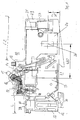
- FIG. 1 shows an insight into an installation switching device 10, the housing 11 of which T shape with a crossbar 12 and a web 13 running perpendicular to it having. From the end face 14 of the web 13, a switching knob 15 protrudes an axis 16 is rotatably mounted and with which a switching mechanism 17 can be actuated can to a contact lever 18 from an on position to an off position and spend back.
- the switch lock 17 has a not shown Latching point, on which a slide 18 shown in FIG. 2 can act; at the Slider 18 attacks a bimetal 19.
- An electromagnetic system which responds to short circuits, with an armature 19 shown in broken lines being provided is that cooperates with a double arm lever 20, the anchor according to Direction of arrow 21 pivoted the double arm lever 20 counterclockwise ; the other arm of the double arm lever 20 acts on the slide 18 and thus on the latching point in the switching lock 17.
- the Anchor When triggered, the Anchor at the same time on the movable contact lever 18 and tears it into his open position.
- the double arm lever 20 is rotatably mounted on an axis of rotation 22. In this respect, a conventional circuit breaker is shown.
- Fig. 1 From Fig. 1 it can be seen that the crossbar 12 to the left of the web 13 over this protrudes only by a length L, whereas the length L2 of the right in the drawing area 23 is more than twice as long. This will inside the case in the crossbar 12 in the area 23 on the right in the drawing Room 24 won, in which a circuit board 25 can be used, on which not Switching elements shown in detail and a summation current transformer 26 attached can be.
- the length of the partial region 27 of the crossbar is chosen such that also a terminal, not shown, can be installed, wherein this terminal is accessible through an access opening 28 for a tool.
- a recess 31 is provided with which the installation device also on a Hat profile mounting rail, not shown, can be snapped on.
- a piezo element is activated when a fault current occurs, which is designed as a strip bender and in the configurations of the individual Figures is arranged differently.
- the strip bender 32 runs parallel to the fastening plane 30, wherein the bendable end 33 is located towards the space 29.
- the the other end 34 is firmly clamped on the side opposite the space 29.
- the end 33 of the strip bender 32 acts on an approximately L-shaped lever, which serves as a coupling piece 35.
- a bearing 37 is provided at one end of the perpendicular to the mounting plane 30 extending arm 36 with which Coupling piece 35 is mounted stationary in the installation switching device 10.
- the other arm 38 is closer to the end faces 14 and acts on the arm with its free end 201 of the double arm lever 20; a nose 39 is provided in the area of the axis of rotation 37, which protrudes into the bending path of the end 33 of the strip bender 32; in the event of of a fault current, the strip bender 32 bends clockwise and pivots about the nose 39, the coupling piece 35 counterclockwise, whereby the coupling piece acts on the arm 201 of the double arm lever 20; about the latch 18 is released from the slide 18.
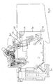
- a strip bender 40 is provided, which is vertical to the mounting level 30 and stationary in the area of the mounting level at 41 is clamped.
- the strip bender 40 acts on one serving as a coupling element Slider element 42, which in the present embodiment has an elongated hole 43 has, with which it is guided along a nose or ledge 44 moves.
- the Coupling piece 42 runs parallel to the mounting plane 30 and acts on the arm 201 a.
- the strip bender 40 is at an angle alpha to Switching chamber tilted or inclined; with the attachment level 30
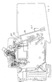
- the strip bender 40 forms the acute angle alpha. Accordingly, the coupling piece 42 rotated by an equal angle, the angle between the Coupling piece 42 and the strip bender 40 is approximately 90 degrees. Starting from the attachment point 41 is the free end of the strip bender 40 to the magnet armature or inclined towards the web 13.
- the angle Alpha 1 between the line is perpendicular extends to the attachment plane 30, enlarged relative to the angle alpha educated.
- a coupling piece 43 is fastened, the coupling piece 43 extends perpendicular to the strip bender 40 and with the Arm 201 interacts.
- the strip bender 32 is closer to End face 14; it acts with its free end 33 on the nose 44 one rotatable with 45 mounted L - shaped coupling 46; the coupling piece 46 is formed as a kind of double lever, the nose 44 the one arm 47 forms; the other arm runs approximately perpendicular to the front end face 14 turned towards the end face 14 and there cooperates with the slide 18. If a fault current occurs, the strip bender bends counterclockwise as shown in FIG. 6 and pivots the coupling piece 46 clockwise. Thereby the slider 18 is moved to unlatch the latching point.
- the residual current detection device can be independent of the mains voltage or dependent on the mains voltage be executed.
- the piezo actuator enables in a voltage dependent Execution an advantageous function down to a mains voltage of 50 V.
Landscapes
- Breakers (AREA)
- Keying Circuit Devices (AREA)
Abstract
Description
- Fig. 1 bis 6
- Einsichten in unterschiedlich ausgestaltete Fehlerstromschutzschalter, wobei in Fig. 1 die Fehlerstromerfassungseinrichtung strichpunktiert angedeutet ist.
Claims (12)
- Installationsschaltgerät, mit einem thermischen und elektromagnetischen Auslöser, mit einem Schaltschloß mit einer Verklinkungsstelle, mit einer Kontaktstelle mit einem beweglichen und einem feststehenden Kontaktstück, bei dem bei auftreten eines Überstromes der thermische Auslöser die Verklinkungsstelle entklinkt und damit die Kontaktstellen bleibend öffnet und bei auftreten eines Kurzschlußstromes der elektromagnetische Auslöser das bewegliche Kontaktstück in Öffnungsstellung verbringt, dadurch gekennzeichnet, dass dem Installationsschaltgerät innerhalb seines Gehäuses ein Aktor in Form eines piezoelektrischen Streifenbiegers zugeordnet ist, der ebenfalls auf die Verklinkungsstelle zur bleibenden Öffnung der Kontaktstelle einwirkt, wobei eine Fehlerstromdetektionseinrichtung vorgesehen ist, deren Ausgangssignal bei auftreten eines Fehlerstromes den Aktor ansteuert.
- Installationsschaltgerät nach Anspruch 1, dadurch gekennzeichnet, dass das Gehäuse eine in Richtung der Breitseiten und der Befestigungsseite vorspringende Erweiterung aufweist, die den Aktor zusammen mit der Fehlerstromdetektionseinrichtung aufnimmt.
- Installationsschaltgerät nach einem der vorigen Ansprüche, dadurch gekennzeichnet, dass der Aktor etwa parallel zur Befestigung Ebene verläuft.
- Installationsschaltgerät nach einem der Ansprüche 1 und 2, dadurch gekennzeichnet, dass der Aktor etwa senkrecht zur Befestigungsebene angeordnet ist, wobei seine Einspannstelle an dem der Befestigungsebene zugewandten Ende liegt.
- Installationsschaltgerät nach Anspruch 4, dadurch gekennzeichnet, dass der Aktor unter einem Winkel ungleich 90 Grad zur Befestigungsebene geneigt ist.
- Installationsschaltgerät nach einem der vorigen Ansprüche, dadurch gekennzeichnet, dass der Aktor direkt auf die Verklinkungsstelle einwirkt.
- Installationsschaltgerät nach einem der Ansprüche 1 bis 5, wobei dem Anker ein Doppelarmhebel zugeordnet ist, der auf einen etwa parallel zur Befestigungsebene verlaufenden Schieber einwirkt, auf die in auch der thermische Auslöser einwirkt, und über die in die Verklinkungsstelle entklinkt wird, dadurch gekennzeichnet, dass der Aktor auf den Schieber einwirkt.
- Installationsschaltgerät nach einem der vorigen Ansprüche 1 bis 6, dadurch gekennzeichnet, dass der Aktor über ein Kupplungsstück auf die Verklinkungsstelle einwirkt.
- Installationsschaltgerät nach Anspruch 8, dadurch gekennzeichnet, dass das Kupplungsstück ein L-förmiger Hebel ist, dessen eines Armende drehbar gelagert ist und im Bereich der Drehachse eine Nase aufweist, auf die der Aktor einwirkt.
- Installationsschaltgerät nach einem der Ansprüche 1 bis 8, dadurch gekennzeichnet, dass das Kupplungsstück ein Schieberelement ist.
- Installationsschaltgerät nach einem der vorigen Ansprüche, dadurch gekennzeichnet, dass das Kupplungsstück auf den Doppelarmhebel einwirkt.
- Installationsschaltgerät nach einem der vorigen Ansprüche, dadurch gekennzeichnet, dass das Kupplungsstück am Aktor befestigt ist.
Applications Claiming Priority (2)
| Application Number | Priority Date | Filing Date | Title |
|---|---|---|---|
| DE10118098A DE10118098A1 (de) | 2001-04-11 | 2001-04-11 | Installationsschaltgerät |
| DE10118098 | 2001-04-11 |
Publications (2)
| Publication Number | Publication Date |
|---|---|
| EP1249852A2 true EP1249852A2 (de) | 2002-10-16 |
| EP1249852A3 EP1249852A3 (de) | 2004-08-04 |
Family
ID=7681240
Family Applications (1)
| Application Number | Title | Priority Date | Filing Date |
|---|---|---|---|
| EP02007824A Withdrawn EP1249852A3 (de) | 2001-04-11 | 2002-04-08 | Installationsgerät |
Country Status (3)
| Country | Link |
|---|---|
| US (1) | US20020149462A1 (de) |
| EP (1) | EP1249852A3 (de) |
| DE (1) | DE10118098A1 (de) |
Cited By (5)
| Publication number | Priority date | Publication date | Assignee | Title |
|---|---|---|---|---|
| EP2073240A1 (de) * | 2007-12-20 | 2009-06-24 | Schneider Electric Industries SAS | Modulares elektrisches Schutzgerät, das über eine zusätzliche elektrische Funktion wie etwa eine Differentialschutzfunktion verfügt |
| CN101752148A (zh) * | 2008-12-12 | 2010-06-23 | 施耐德电器工业公司 | 带选择性的断路器 |
| CN101409181B (zh) * | 2007-10-09 | 2013-03-27 | 西门子公司 | 保护开关装置和保护开关仪器 |
| CN104701111A (zh) * | 2015-03-19 | 2015-06-10 | 河北宝凯电气有限公司 | 一种可快速分断的小型断路器 |
| CN104715980A (zh) * | 2015-03-19 | 2015-06-17 | 河北宝凯电气有限公司 | 一种磁后备脱扣保护机构 |
Families Citing this family (5)
| Publication number | Priority date | Publication date | Assignee | Title |
|---|---|---|---|---|
| US6642832B2 (en) * | 2000-12-08 | 2003-11-04 | Texas Instruments Incorporated | ARC responsive thermal circuit breaker |
| DE10340003B4 (de) * | 2003-08-29 | 2006-02-16 | Siemens Ag | Kurzschluss- und Überlastauslöser für ein Schaltgerät |
| FR2884962A1 (fr) * | 2005-04-22 | 2006-10-27 | Norbert Roger Beyrard | Contacteur disjoncteur a ouverture par declenchement a l'aide d'un actuateur piezo electrique. |
| ITMI20072278A1 (it) * | 2007-12-04 | 2009-06-05 | Abb Spa | Interruttore automatico per applicazioni di bassa tensione. |
| WO2021160179A1 (zh) * | 2020-02-13 | 2021-08-19 | 浙江正泰电器股份有限公司 | 断路器 |
Family Cites Families (4)
| Publication number | Priority date | Publication date | Assignee | Title |
|---|---|---|---|---|
| DE3643511A1 (de) * | 1986-12-19 | 1988-06-30 | Felten & Guilleaume Energie | Mechanismus fuer einen mit einem leitungsschutzschalter kombinierten fehlerstromschutzschalter |
| DE4443520A1 (de) * | 1994-12-07 | 1996-06-13 | Abb Patent Gmbh | Fehlerstromschutzschalter |
| FR2779568B1 (fr) * | 1998-06-04 | 2000-07-13 | Schneider Electric Ind Sa | Dispositif de coupure electrique comprenant un dispositif de declenchement differentiel et disjoncteur comprenant un tel dispositif |
| EP1171898B1 (de) * | 1999-04-19 | 2003-10-08 | PBT (IP) Limited | Integrierter und elektrisch betätigter mechanischer auslösemechanismus |
-
2001
- 2001-04-11 DE DE10118098A patent/DE10118098A1/de not_active Withdrawn
-
2002
- 2002-04-08 EP EP02007824A patent/EP1249852A3/de not_active Withdrawn
- 2002-04-11 US US10/122,485 patent/US20020149462A1/en not_active Abandoned
Cited By (12)
| Publication number | Priority date | Publication date | Assignee | Title |
|---|---|---|---|---|
| CN101409181B (zh) * | 2007-10-09 | 2013-03-27 | 西门子公司 | 保护开关装置和保护开关仪器 |
| EP2073240A1 (de) * | 2007-12-20 | 2009-06-24 | Schneider Electric Industries SAS | Modulares elektrisches Schutzgerät, das über eine zusätzliche elektrische Funktion wie etwa eine Differentialschutzfunktion verfügt |
| FR2925756A1 (fr) * | 2007-12-20 | 2009-06-26 | Schneider Electric Ind Sas | Appareil de protection electrique modulaire comportant une fonction electrique complementaire telle la fonction protection differentielle |
| CN101465249B (zh) * | 2007-12-20 | 2015-05-13 | 施耐德电器工业公司 | 包括例如差动保护功能等补充电功能的模块保护单元 |
| CN101752148A (zh) * | 2008-12-12 | 2010-06-23 | 施耐德电器工业公司 | 带选择性的断路器 |
| CN101752148B (zh) * | 2008-12-12 | 2014-08-13 | 施耐德电器工业公司 | 带选择性的断路器 |
| CN104701111A (zh) * | 2015-03-19 | 2015-06-10 | 河北宝凯电气有限公司 | 一种可快速分断的小型断路器 |
| CN104715980A (zh) * | 2015-03-19 | 2015-06-17 | 河北宝凯电气有限公司 | 一种磁后备脱扣保护机构 |
| WO2016146083A1 (zh) * | 2015-03-19 | 2016-09-22 | 河北宝凯电气股份有限公司 | 一种可快速分断的小型断路器 |
| CN104715980B (zh) * | 2015-03-19 | 2017-01-25 | 河北宝凯电气股份有限公司 | 一种磁后备脱扣保护机构 |
| CN104701111B (zh) * | 2015-03-19 | 2017-03-22 | 河北宝凯电气股份有限公司 | 一种可快速分断的小型断路器 |
| US10347455B2 (en) | 2015-03-19 | 2019-07-09 | Hebei Bao Kay Electric Co., Ltd | Miniature circuit breaker capable of rapid breaking |
Also Published As
| Publication number | Publication date |
|---|---|
| DE10118098A1 (de) | 2002-10-17 |
| US20020149462A1 (en) | 2002-10-17 |
| EP1249852A3 (de) | 2004-08-04 |
Similar Documents
| Publication | Publication Date | Title |
|---|---|---|
| DE69401971T2 (de) | Magnetothermische Auslöseeinheit | |
| EP0042113A2 (de) | Selbstschalter | |
| EP1249852A2 (de) | Installationsgerät | |
| AT509278A1 (de) | Auslösemodul für ein schaltgerät | |
| DE3713537A1 (de) | Umkehr-schaltvorrichtung mit ueberstromschutz | |
| EP1760748B1 (de) | Elektrisches Schaltgerät | |
| DE102011008831A1 (de) | Istallationsschaltgerät | |
| EP1760747B1 (de) | Elektrisches Schaltgerät | |
| DE69024734T2 (de) | Lastschalter mit magnetischem Auslöser für niedrige Überströme | |
| DE10037924A1 (de) | Unterbrechermechanismus für Schaltautomaten | |
| DE10216439A1 (de) | Hilfsschalter | |
| DE2616554C2 (de) | Elektrischer Installationsschalter, insbesondere Leitungsschutzschalter mit Fehlerstromschutzeinrichtung | |
| DE2343908C2 (de) | Stromunterbrecher mit Überstrom- und Hilfs-Auslösung | |
| DE102008016575A1 (de) | Voll-Schutzschalter | |
| WO2001069630A1 (de) | Auslösevorrichtung für einen leistungsschalter | |
| EP2095388B1 (de) | Installationsschaltgerät mit einer doppelunterbrechung | |
| EP0279363A2 (de) | Fehlerstromschutzschalter | |
| DE4309197A1 (de) | Leitungsschutzschalter | |
| DE19832573C2 (de) | Batterietrennschalter | |
| EP0043020A1 (de) | Elektrisches Installationsgerät, insbesondere Selbstschalter | |
| EP0849759A1 (de) | Installationsschaltgerät | |
| DE102005046640B4 (de) | Elektrisches Installationsgerät | |
| EP1488438B1 (de) | Leitungsschutzschalter mit zweipoliger unterbrechung | |
| EP0616350A1 (de) | Leitungsschutzschalter | |
| DE102006036194B4 (de) | Schaltvorrichtung mit Schaltstellenpaar |
Legal Events
| Date | Code | Title | Description |
|---|---|---|---|
| PUAI | Public reference made under article 153(3) epc to a published international application that has entered the european phase |
Free format text: ORIGINAL CODE: 0009012 |
|
| AK | Designated contracting states |
Kind code of ref document: A2 Designated state(s): AT BE CH CY DE DK ES FI FR GB GR IE IT LI LU MC NL PT SE TR |
|
| AX | Request for extension of the european patent |
Free format text: AL;LT;LV;MK;RO;SI |
|
| PUAL | Search report despatched |
Free format text: ORIGINAL CODE: 0009013 |
|
| AK | Designated contracting states |
Kind code of ref document: A3 Designated state(s): AT BE CH CY DE DK ES FI FR GB GR IE IT LI LU MC NL PT SE TR |
|
| AX | Request for extension of the european patent |
Extension state: AL LT LV MK RO SI |
|
| RIC1 | Information provided on ipc code assigned before grant |
Ipc: 7H 01H 83/20 B Ipc: 7H 01H 71/12 A |
|
| 17P | Request for examination filed |
Effective date: 20040827 |
|
| AKX | Designation fees paid |
Designated state(s): DE FR GB IT |
|
| RBV | Designated contracting states (corrected) |
Designated state(s): DE FR GB IT |
|
| 17Q | First examination report despatched |
Effective date: 20090803 |
|
| STAA | Information on the status of an ep patent application or granted ep patent |
Free format text: STATUS: THE APPLICATION IS DEEMED TO BE WITHDRAWN |
|
| 18D | Application deemed to be withdrawn |
Effective date: 20091215 |